IMPORTANT:
WARRANTY
Before using any MONITECH product please carefully
review this Manual as well as any additional
documentation provided with your shipment.
Attempting any of the following will void product warranty:
•unauthorized repairs or parts replacement
•inappropriate use or placement: exposing product
to liquids, harmful gases, electrical shock, physical
shock, temperatures beyond the range of -4°F to
140°F
(-20°C to 60°C)
•use of electrical voltage other than 12V 4.16A
(power supply and AC cable provided)
•Removal or modification of serial, product, or
warranty labels.
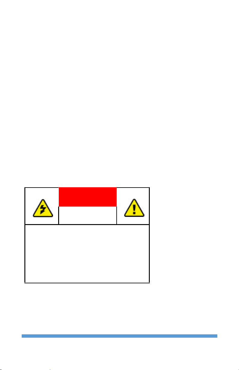
ELECTRICAL HAZARD
DO NOT OPEN
TO AVOID ELECTRICAL SHOCK DO NOT
OPEN PRODUCT CASING. UNAUTHORIZED
REPAIRS OR PARTS REPLACEMENT ARE
PROHIBITED AND WILL VOID PRODUCT
WARRANTY. PLEASE RETURN TO
MONITECH FOR REPAIRS.