Monnit mug11 User manual

Information to Users
This equipment has been tested and found to comply with the limits for a Class B digital de-
vices, pursuant to Part 15 of the FCC Rules. These limits are designed to provide reasonable
protection against harmful interference in a residential installation. This equipment gener-
ates, uses, and can radiate radio frequency energy and, if not installed and used in accor-
dance with the instruction manual, may cause harmful interference to radio communications.
However, there is no guarantee that interference will not occur in a particular installation. If
this equipment does cause harmful interference to radio or television reception, which can be
determined by turning the equipment o and on, the user is encouraged to try to correct the
interference by one of more of the following measures:
• Reorient or relocate the receiving antenna
• Increase the separation between the equipment and receiver
• Connect the equipment into an outlet on a circuit dierent from that to which
the receiver is connected.
• Consult the dealer or an experienced radio/TV technician for help.
WARNING: Changes or modications not expressly approved by Monnit could void the user’s
authority to operate the equipment.
RF EXPOSURE WARNING: To satisfy FCC RF exposure requirements for mobile transmitting
devices, a separation distance of 20 cm or more should be maintained between the antenna
of this device and persons during device operation. To ensure compliance, operations at
closer than this distance are not recommended. The antenna used for this transmitter must
not be co-located in conjunction with any other antenna or transmitter.
The primary function of the Range Extender is to act as a range extender in places
where wireless sensors are out of range of a Monnit wireless gateway.
Inside the Box
You should nd the following items in the box:
• Monnit Wireless Range Extender
• Antenna
Monnit Wireless
Range Extender
Product Use Guide

PAGE 2
Monnit Wireless Range Extender Principle of Operation
On power up, the range extender will locate a gateway that has the
“best” wireless signal available. The device then auto-congures itself
to communicate and link with this gateway. After linking with the parent
gateway, it then establishes itself as a sub-network with it’s own dedicated
channel to the gateway, relieving congestion from multi-sensor networks.
Delays Associated with Using Wireless Range Extenders
Data coming from a sensor is delivered to a range extender and forwarded
onto the gateway. In all implementations where network trac is kept
below 6 messages per minute, the worst-case lag through a range
extender to the network is 20 seconds. If more than 6 messages are gen-
erated by wireless sensors talking through a range extender, it is possible
to experience data lag beyond 20 seconds.
Monnit Wireless Range Extender Features
• Extends the coverage area of your wireless sensor network.
• Supports 6 messages / minute.
• Built in memory can queue up to 30,000 messages for delivery to
the gateway.
• AC powered, so no batteries needed.
* Important - If the range extender is unplugged or loses power, all
sensor messages stored on the device will be lost!
1.417 in
(35.992 mm)
3.090 in
(78.486 mm)
2.085 in
(52.959 mm)

PAGE 3
Using the Wireless Range Extender
1. Adding a Wireless Range Extender to a Sensor Network
Monnit wireless range extenders can be added to any Monnit sensor
network through the iMonnit online sensor monitoring software.
Steps to add Wireless Range Extenders to your Sensor Network.
• Choose “Manage” from the main navigation.
• Select the network you would like to add the range extenders to.
• Find the bottom of the section “Sensor List / Assign Sensor”.
• Enter the ID and Security Code from the back label of the
range extender.
• Press the “Assign Sensor” button.
• Repeat this process to add more range extenders to the network.
Once the range extender has been added to your network, you will need
to update and push the sensor device list to your range extender so it
knows what sensors to allow communication with. For a USB gateway,
go to the Monnit gateway application/service and click “Download
Sensor Updates”. For an Ethernet gateway, power cycle the device by
unplugging it, waiting 10 seconds then plugging it back in. For a
Cellular gateway, use the power button to turn it o, wait 10 seconds
then turn it back on.
After resetting the gateway, plug the range extender into an AC wall
outlet. The range extender will have a green light when it has found the
network. If the light is steady red, check the network, unplug it and try
again.
Contains FCC ID: ZTL-RFSC1
and IC: 9794A-RFSC1
This device complies with Part 15 of the FCC
Rules. Operation is subject to the following
two conditions:
(1) this device may not cause harmful
interference and
(2) this device must accept any interference
received, including interference that may
cause undesired operation.
www.monnit.com
PN: SCM-91A-0RP
© 2012 Monnit Corp.
ID: ######
Code: XXXXXX

PAGE 4
2. Wireless Range Extender Light Indicator
Flashing Red/Green – the range extender is looking for a gateway to join.
Solid Red - no network found.
Solid Green – range extender has joined a network.
Flashing Green – sensor data trac is intercepted and relayed.
3. Wireless Range Extender Data
The range extender reports on ve data parameters. The rst, DCnt, is
for Device Count and indicates how many sensors the range extender
is able to recognize as being in the network. This count may add up to
all sensors in the network, or it may only indicate those sensors that are
talking through it, depending on how the range extender was able to
provision its network.
Rxm stands for Received Messages. In the above example, there were 7
messages that were picked up by the range extender and sent through to
the network.
Fls stands for Failures. In the event that network trac overwhelms the
range extender, the number of messages that were attempted to be
delivered but failed are recorded.
Qu stands for Queue. If the range extender is overwhelmed with
message trac, it will report on the number of messages it has queued,
but has not delivered up to the network. As the range extender recovers,
this number will dwindle until it gets back to 1 as messages are success-
fully delivered up to the network.
Chan stands for Channel. In the process of forming a sub network, the
range extender picks a dierent channel to communicate to the sensors
on, to help avoid accumulating too much trac on the same network.

PAGE 5
4. Wireless Range Extender - Determining Connections
When using sensors with a wireless range extender, the sensors will
automatically connect to the device with the strongest signal. The
range extender should be placed between the sensor and the gateway.
If the sensor detects a stronger signal from the range extender, it will
automatically connect to the range extender.
If the sensor detects a stronger signal from the gateway, it will
automatically connect to the gateway and ignore the range extender.
Wireless
Sensor
Wireless Gateway
Range
Extender
Wireless
Sensor
Wireless Gateway
Stronger Signal
Range
Extender
Wireless
Sensor
Wireless Gateway
Stronger Signal
Range
Extender

PAGE 6
Monnit Wireless Range Extender Specications
Power
Standard Operating Range 100-240 VAC
Max Operating Range 90-264 VAC
Input Frequency 50/60Hz +/- 3Hz
Max Power Consumption 1.0W
Wireless Operation
Maximum Wireless Devices Per Gateway Up to 100 Total Wireless Devices Per Gateway
Maximum Sensors Per Range Extender Up to 99 Wireless Devices (Range extenders
count as wireless devices)
Message Storage / Memory 30,000 Messages
Recommended Network Communications Up to 6 Messages Per Minute
Range Extender Communication Delay Up to 30 Seconds
(At number of recommended network com-
munications)
Mechanical
LEDs Single LED H/W Status / Activity
- Flashing Red/Green
(looking for a gateway to join)
- Solid Red (no network found)
- Solid Green
(has joined a network)
- Flashing Green
(sensor data is intercepted and relayed)
Enclosure ABS Plastic
UL94V-0 Flame Rating
Dimensions 3.09 x 2.085 x 1.417 in.
(78.486 x 52.959 x 35.992 mm)
Weight 4.5 ounces
Environmental
Operating Temperature -40° to +85° C (-40° to +185° F)
FCC Approval: ZTL- RFSC1

PAGE 7
Monnit Wireless Range Extender FAQs
Will the range extender work with my current iMonnit Gateway and
Monnit Express software?
It is advised to upgrade your Monnit Gateway and Monnit Express software to
the latest version to help avoid issues while setting up and using your wireless
sensors through a range extender. To update your software, please visit http://
www.monnit.com/support.
How can I tell if I need a range extender?
Use a Monnit Button Sensor to assess the expected range of your environ-
ment. If the button sensor struggles to communicate with the gateway by
ashing red, even occasionally, it is likely that any other sensor placed in
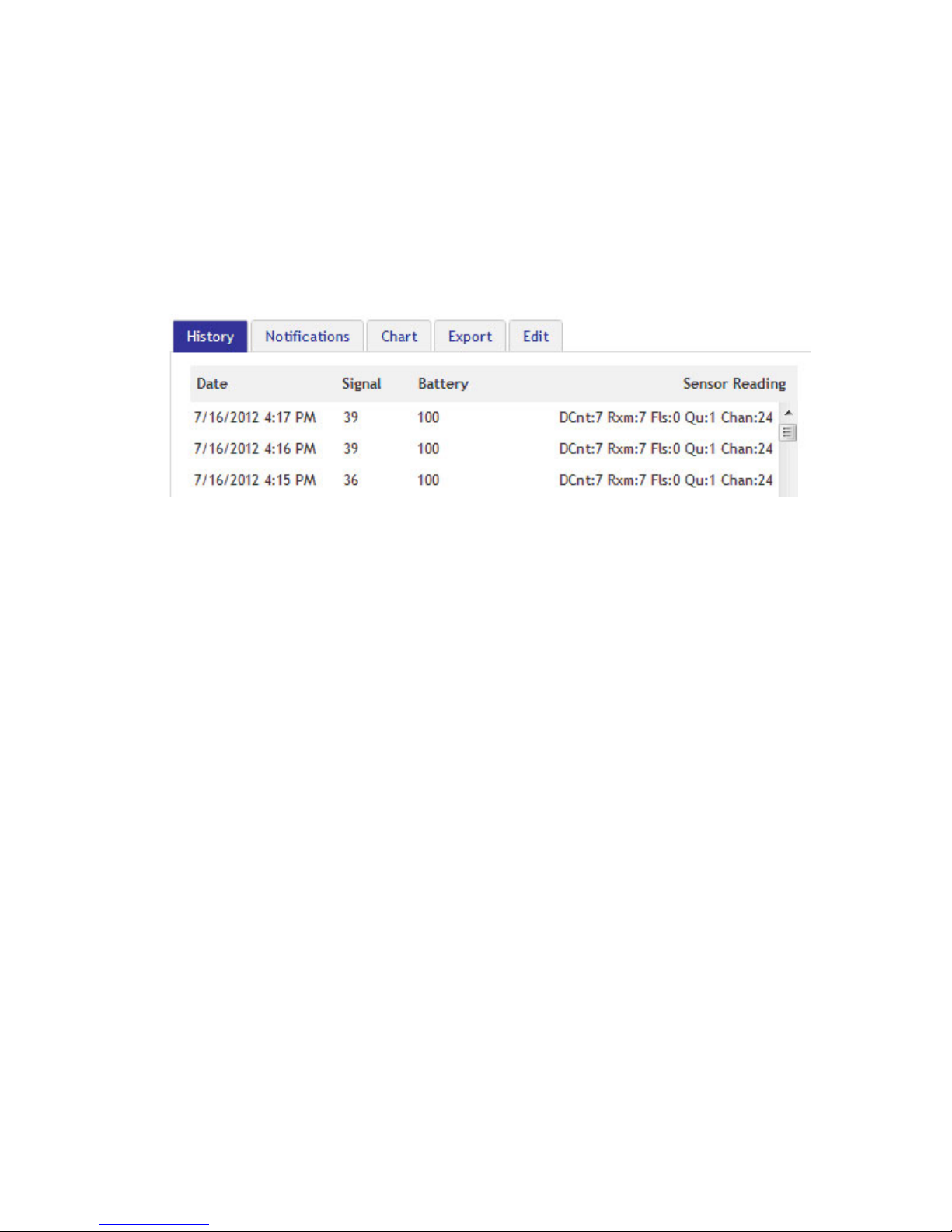
the same location will struggle. You can also view the history of an oper-
ating sensor to see if you are getting good signal strength. If the signal
strength is less than 50, or your button sensor is ashing red, even just
occasionally, placing a range extender in between is advised.
Is the repeater compatible with my existing network?
If your existing network version begins with 2.x.x.x, the range extender is
compatible. Any previous versions, 1.2.xxx, are not compatible.
What is the increase in range?
The range essentially doubles when a range extender is placed on the
network. Depending on the environment, the range extender could in-
crease the range of a sensor by up to 1600 ft. Multiple range extenders can
be chained together to allow for even further range. (Note that in multiple
range extender networks, for every relay point the number of messages
doubles.)
Does the range extender lose data if it is not able to deliver
immediately?
No, as long as the range extender has not lost communication with the
network. If the range extender still has a link to the network, but has been
unable to deliver a message because of network trac or due to failures, it
has the ability to store all data messages coming in. They will be delivered
one after another as soon as the communication link is clear again.

For additional information or more detailed instructions
on how to use your Monnit Wireless Sensors or sensor
monitoring software, please visit us on the web at
http://www.monnit.com/support/.
M-UG11-2B (09/15)
Monnit Corporation
4403 South 500 West
Murray, UT 84123
801-561-5555
www.monnit.com
Monnit, Monnit Logo and all other trademarks are property of Monnit, Corp.
© 2009-2015 Monnit Corp. All Rights Reserved.
Other Monnit Extender manuals