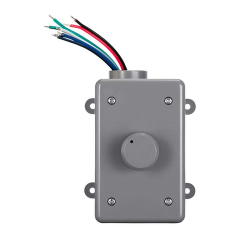
Monoprice OVC100 User manual

1
OVC100 100-Watt Impedance Matching Outdoor Volume Control
P/N 38177
Quick Install Guide
INTRODUCTION
This Impedance Matching Outdoor Volume Control allows you to connect multiple speaker
pairs to a single power amplifier or receiver. It increases (or decreases) the impedance of
the connected speaker pair to ensure that the overall impedance level presented to the
amplifier is high enough to prevent damage to the amplifier. It can support amplifiers with
up to 100 watts of output power and has a waterproof enclosure, allowing it to be used in
outdoor applications.
INSTALLATION
Perform the following steps to install one or more volume controls to your stereo system.
These instructions assume that you have already installed all speaker pairs and low-voltage
mounting brackets at the desired locations.
1. Refer to your amplifier's manual to determine the minimum impedance level that
can be safely connected. In most cases, the minimum impedance is 4, 6, or 8 ohms,
though some amplifiers are stable down to 2 ohms.
2. Determine how many speaker pairs are to be connected and the nominal
impedance of each pair. Note that only a single pair of speakers should be
connected to each volume control.
3. Refer to the following tables to determine the switch settings for each
volume control, depending on the minimum impedance load of your
amplifier, then set the switches on all volume controls to the indicated value.

2
8-Ohm Capable Amplifier
Number of 8-Ohm
Speaker Pairs
Switch Position
1-4 pairs
4x
5-8 pairs
8x
More than 8 pairs
Not
Recommended
6-Ohm Capable Amplifier
Number of 8-Ohm
Speaker Pairs
Switch Position
1-5 pairs
4x
6-10 pairs
8x
More than 10 pairs
Not
Recommended
4-Ohm Capable Amplifier
Number of 8-Ohm
Speaker Pairs
Switch Position
1 pair
1/2x
2-8 pairs
4x
9-16 pairs
8x
More than 16 pairs
Not
Recommended
8-Ohm Capable Amplifier
Number of 4-Ohm
Speaker Pairs
Switch Position
1-4 pairs
8x
More than 4 pairs
Not
Recommended
6-Ohm Capable Amplifier
Number of 4-Ohm
Speaker Pairs
Switch Position
1-2 pairs
4x
3-5 pairs
8x
More than 5 pairs
Not
Recommended
4-Ohm Capable Amplifier
Number of 4-Ohm
Speaker Pairs
Switch Position
1-4 pairs
4x
5-8 pairs
8x
More than 8 pairs
Not
Recommended

3
4. If conduit is to be used, run four 2-conductor wires
from each of the two speakers and the amplifier, up
through the conduit and into the enclosure. If conduit
is not to be used, run one outdoor rated speaker wire
from each speaker and two from the amplifier. Mark
each end of the two speaker wires from the amplifier
as left-channel and right-channel.
5. If conduit is used, mount the enclosure onto the conduit using the appropriate
adhesive.
6. Use the four holes on the back of the enclosure to mount it to a stationary object or
wall.
7. Connect the left-channel speaker wire to the left-channel speaker, taking note of
the wire colors or markings used for the positive (+) and negative (-) connections.
For best results, always use the same wire colors or markings for the positive and negative
connections.
8. Connect the other end of the left-channel speaker wire to the L+ and L- Output
terminals on the volume control, taking care to match the polarity.
9. Connect the right-channel speaker wire to the right-channel speaker, taking note of
the wire colors or markings used for the positive (+) and negative (-) connections.
10. Connect the other end of the right-channel speaker wire to the R+ and R- Output
terminals on the volume control, taking care to match the polarity.
11. Connect the left-channel amplifier wire to the L+ and L- Input terminals on the
volume control, taking note of the wire colors or markings used for the positive (+)
and negative (-) connections.
12. Connect the right-channel amplifier wire to the R+ and R- Input terminals on the
volume control, taking note of the wire colors or markings used for the positive (+)
and negative (-) connections.
13. Insert the volume control into the enclosure, taking care to ensure
that the wires do not come loose from their connections or become
pinched or shorted.

4
14. Ensure that the rubber gasket is in place behind the cover plate,
place it over the enclosure and secure it in place with the screws
provided.
15. Place the volume knob onto the volume control post.
16. Repeat steps 4-15 for each additional speaker pair, enclosure, and
volume control.
17. Ensure that the amplifier is powered off and unplugged from the power source.
18. At the amplifier, use a terminal block or wire nut to connect all the left-channel
negative (-) wires and a short length of speaker wire together.
19. Connect the negative lead on the short length of speaker wire to the left-channel
negative (-) terminal on the amplifier.
20. Repeat steps 18-19 for the left-channel positive (+) lead.
21. Repeat steps 18-20 for the right-channel negative (-) and positive (+) leads. The
image below illustrates a proper connection for two volume controls.

5
22. Determine which speaker pair you want to be the loudest, then turn the volume
control fully clockwise to the maximum position. If all zones are to be the same
volume level, set all volume controls to the maximum level.
23. Set the volume control on the amplifier to the minimum level.
24. Plug in and power on the amplifier.
25. Start audio playback, then slowly increase the volume control on the amplifier until
the volume level in the selected room(s) are at the maximum level you will want
with no distortion. If distortion can be heard, reduce the volume level until
distortion can no longer be heard.
26. Leave the volume control on the amplifier at the set position, then use the
individual zone volume controls to set the volume in each zone to a comfortable
listening level.
ONLINE SUPPORT
Monoprice is pleased to provide free online support. For order related issues, contact the
Customer Service department through the Live Chat link on our website
For technical issues, contact the Technical Support department through the online chat
Check the website for support times and links.

6
SPECIFICATIONS
Model
38177
Maximum Power Capacity (RMS)
100 watts
Frequency Response
20Hz ~ 20kHz
Total Maximum Attenuation
42dB
Supported Wire Gauges
14-16 AWG
Impedance Matching Multipliers
1/2x, 4x, and 8x
Dimensions
3.0" x 5.1" x 4.0"
Table of contents
Other Monoprice Control Unit manuals
Popular Control Unit manuals by other brands

Pittway
Pittway System Sensor M500DR Installation and maintenance instructions

Vag
Vag EKN H1200 PS10 Operation manual

MSI
MSI LT Technical manual

Rock Seven
Rock Seven RockBLOCK 9603 Developer's guide

Samson
Samson 2371 Series Mounting and operating instructions

Veeder-Root
Veeder-Root TLS-350 Series installation guide