Manual / DE
INHALT
4 x Beine 16 × 4.2 × 13.5 mm 16 x Senkschraube
Ø4,0 - 15 mm zur
Nachrüstung
Bohrschablone
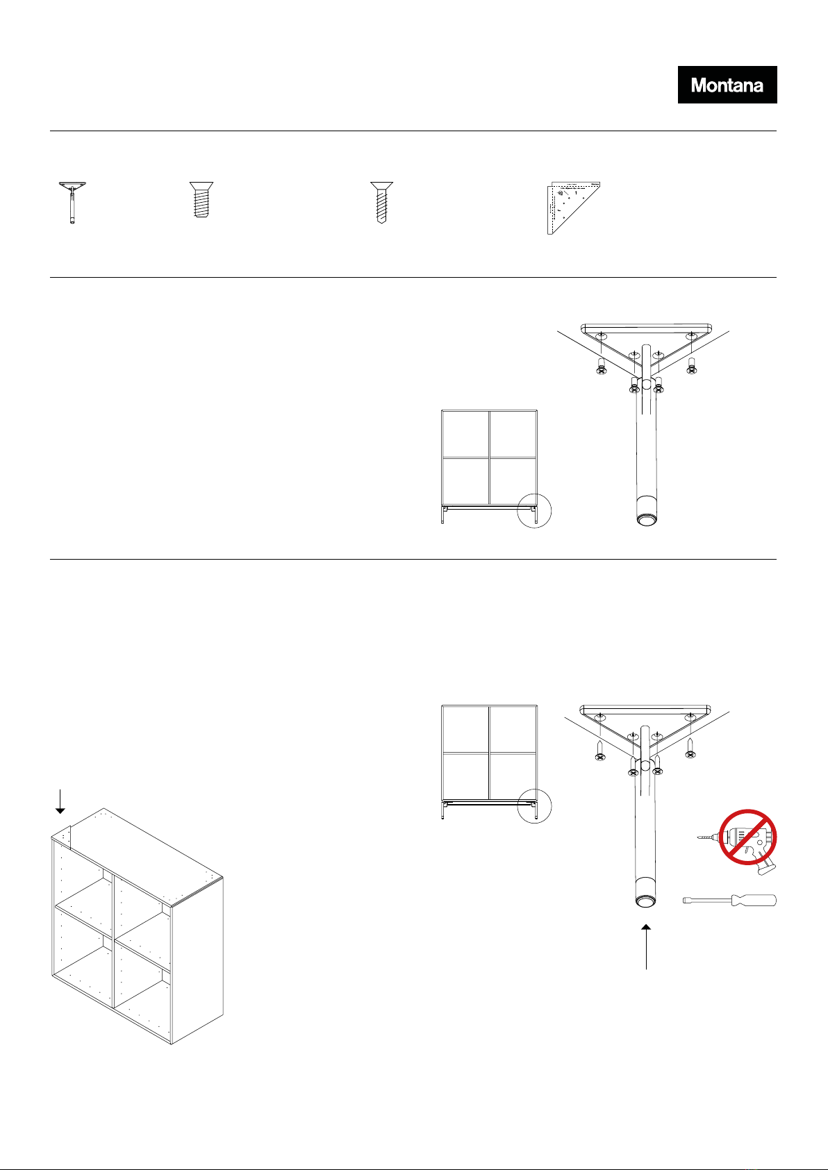
Falls die Beine zusammen mit einem Modul bestellt wer-
den, dann benden sich in jeder Ecke des Modulbodens
4 Löcher, um die Beinen zu montieren.
Verwenden Sie 16 Stück 4,2 × 13,5 mm Schrauben.
MONTAGE
1. Position bestimmen
Falls das Modul an einer Wand aufgestellt wird, kann
es von Vorteil sein, die hinteren Beine unter dem Modul
etwas nach innen zu bewegen. Dann kann das Modul zie-
mlich nahe an der Wand platziert werden, während sich
die Beine und die Fußleiste nicht berühren.
3. Befestigung der Beine
Die Beine werden mit den beigefügten ø4 × 15 mm
Schrauben befestigt. Achten Sie darauf, dass die
Schrauben keinen Schaden nehmen. Verwenden Sie zum
endgültigen Nachziehen der Schrauben immer einen
Handschraubendreher.
4. Einstellung
Das Modul wird mit den Einstellschrauben in den Beinen
nivelliert.
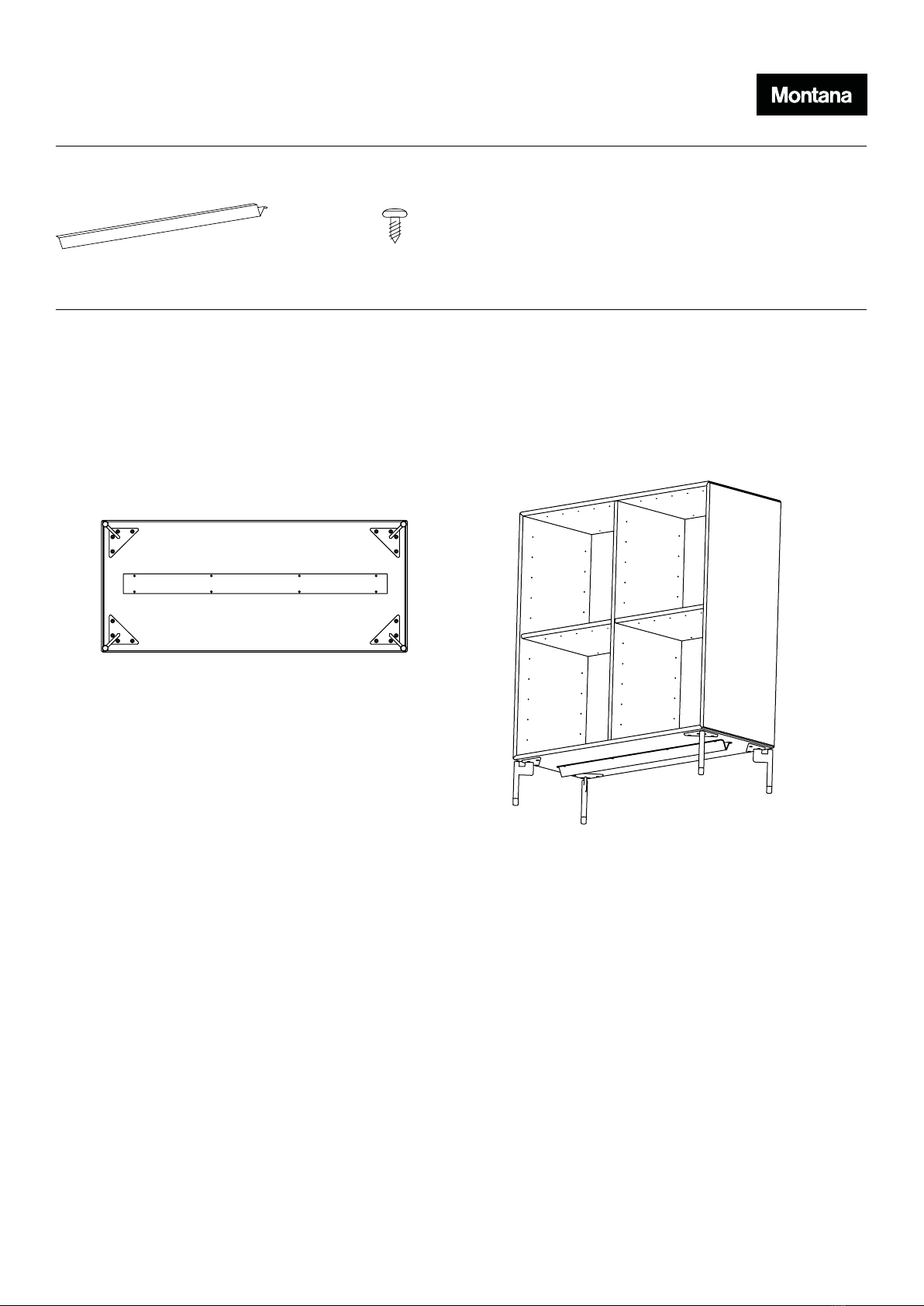
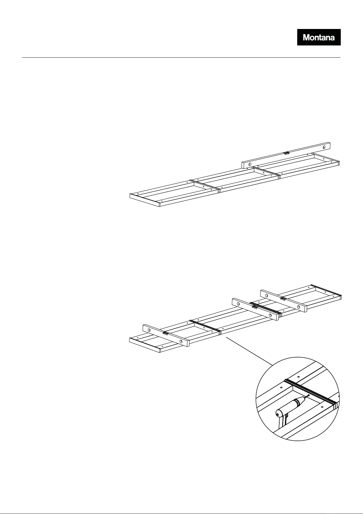
HINWEIS:
Einheiten ab einer Breite von 69,6 cm mit Beinen sind mit einer Stützschiene unter dem Boden zu versehen.
2. Kennzeichnung
Falls die Beine zur Nachrüstung bestellt werden, dann
verwenden Sie bitte das beiliegende Muster, um die Posi-
tion der Beine zu bestimmen.
NACHRÜSTUNG