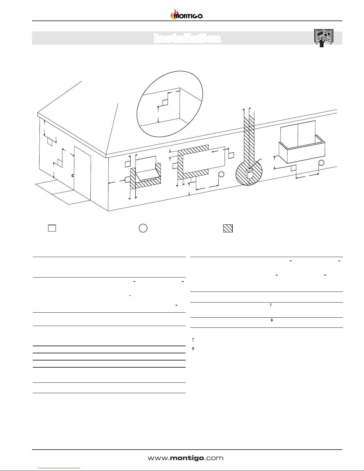
Montigo PVHEX58-300 Instruction Manual

IF YOU SMELL GAS
Do not try to light any appliance.
Do not touch any electrical switch; do not use any phone in your building.
Immediately call your gas supplier from a neighbor's phone. Follow the gas
supplier's instructions.
If you cannot reach your gas supplier, call the fire department.
DANGER
Irritant
Cutting
Watchyour step
Slipperyfloor
Hightemperatures
Glasshazard
Dangerof suffocation
Highvoltage
Toxic
Flammablematerials
Corrosive
Forklift trucks
Dangeroverhead crane
Explosionrisk
Oxidising
Dangerof death
Biohazard
LaserRadiation
Dangerof entrapment
Hotsurface
GeneralWarning
Blank
Gasbottles
Watchfor
fallingobjects
Electricity
Dangerfor cutter
Entrapmenthazard
Batteryhazard
Rotatingparts
Lowtemperature
Strongmagnetic field
Opticalradiation
Nonionizing
radiation
Radiation
Hazardousto the
Environment
Dangerof harming
yourhands
Irritant
Cutting
Watchyour step
Slipperyfloor
Hightemperatures
Glasshazard
Dangerof suffocation
Highvoltage
Toxic
Flammablematerials
Corrosive
Forklift trucks
Dangeroverhead crane
Explosionrisk
Oxidising
Dangerof death
Biohazard
LaserRadiation
Dangerof entrapment
Hotsurface
GeneralWarning
Blank
Gasbottles
Watchfor
fallingobjects
Electricity
Dangerfor cutter
Entrapmenthazard
Batteryhazard
Rotatingparts
XG0517 070714
PVHEX58-300 &
PVHEX510-300
5/8 and 5/10
External Wall
Power Vent
Installation & Maintenance Manual
Installer: Leave this manual with the appliance.
Consumer: Retain this manual for future reference.
NOTICE
If the information in these instructions is not followed exactly, a fire or explosion
may result causing property damage, personal injury or death.
WARNING
Canadian Heating Products Inc. Langley, BC V4W 4A1 | Montigo Del Ray Corp. Ferndale, WA 98248
This power vent is approved for use with Montigo fireplaces only and is certified to
ANSI Z21.50 / CSA 2.22 vented gas fireplace standard along with the fireplace.
NOTICE
PVHEX510-300 power vent is approved for use with Montigo R520, R520-ST,
R620-ST, R720, and R820.
NOTICE
PVVEX510-300 power vent is approved for use with Montigo R520, R520-ST,
R620-ST, R720, and R820.
NOTICE
PVHFL510-300 power vent is approved for use with Montigo R520, R520-ST,
R620-ST, R720, and R820.
NOTICE
PVHEX58-300 power vent is approved for use with Montigo R320, R320-ST, R420,
R420-ST, and RP620.
NOTICE
PVVEX58-300 power vent is approved for use with Montigo R320, R320-ST, R420,
R420-ST, and RP620.
NOTICE
PVHFL58-300 power vent is approved for use with Montigo R320, R320-ST, R420,
R420-ST, and RP620.
NOTICE

Introduction
Specications
PVHEX58-300 Horizontal Power Vent System
Safety Alert Key
Page 2 XG0517 - 070714
General Information
This installation guide covers installation of the External Power Vent
System only. This system is designed to allow installation of gas replaces
that cannot be done with a standard Direct Vent gas replace installa-
tion. Only for use on R-Series, R-Series See-Through and RP-Series.
ONLY USE WITH APPROVED FIREPLACES - see replace
installation manual.
Read through the replace's installation & maintenance manual, as it
must also be adhered to.
Power Cord Harnesses:
EPVH10 - 10 foot power cord and harness
EPVH20 - 20 foot power cord and harness
EPVH30 - 30 foot power cord and harness
EPVH40 - 40 foot power cord and harness
EPVH50 - 50 foot power cord and harness
EPVH60 - 60 foot power cord and harness
EPVH70 - 70 foot power cord and harness
EPVH80 - 80 foot power cord and harness
EPVH90 - 90 foot power cord and harness
EPVH100 -100 foot power cord and harness
Before Your Begin
For vent congurations and power vent locations,
refer to replace manual.
Pipe Dimensions PVHEX58-300 ...........5"/8"
Pipe Dimensions PVHEX510-300 .........5"/10"
Maximum Airow: ......................... 300 CFM
Speed: .......................................... 2700 RPM
Power: ............................................ Connect to replace control box
............................................ Refer to replace rating plate

PVHEX58-300 & PVHEX510-300 Horizontal Power Vent
Product Dimensions
Introduction
Figure 1. PVHEX58-300 & PVHEX510-300 (Tolerance ±⅛") [mm]
Side View
Front View
18 1
4
"
465
22 1
4
"
566
17 1
4
"
439
21 1
4
"
541
2"
51
13"
330
41
2
"
114
19 7
8
"
505
91
2
"
241
61
8
"
156
15 7
8
"
403
13"
330
13"
330
5"
127
8"
203
PVHEX58-300 External Horizontal Power Vent
18 1
4
"
465
22 1
4
"
566
17 1
4
"
439
21 1
4
"
541
2"
51
13"
330
41
2
"
114
19 7
8
"
505
91
2
"
241
61
8
"
156
15 7
8
"
403
13"
330
13"
330
5"
127
8"
203
PVHEX58-300 External Horizontal Power Vent
Top View
Rear View
18 1
4
"
465
22 1
4
"
566
17 1
4
"
439
21 1
4
"
541
2"
51
13"
330
41
2
"
114
19 7
8
"
505
91
2
"
241
61
8
"
156
15 7
8
"
403
13"
330
13"
330
5"
127
8"
203
PVHEX58-300 External Horizontal Power Vent
Power Head
Framing Kit
Vent Retainer
Electrical Box
14 1
2
"
368
15 1
4
"
389
Vent Section
Framing
Wall board
Power head
Rough in box
5"
127
PVHEX58-300
PVHEX10-300
10"
254
8"
203
Page 3
XG0517 - 070714

Installing the Power vent
15 1
4
"
389
14 1
2
"
368
Framing
Wall board
Rough in box
Figure 2. Framing dimensions (combustible material construction)
Installation
Step 1: Unscrew Power Head from rough in Box by unscrewing four
screws.
Figure 2a. Unscrewing four screws
Step 2: Remove Power head from rough in box.
Figure 2c.
Unpacking the Power vent
Figure 2b.
PVHEX58-300 & PVHEX510-300 Horizontal Power Vent
Page 4 XG0517 - 070714

Installation
Page 5
XG0518 - 070714
Step 3: Screw rough in box to wall.
Figure 2e.
Step 4: Remove six screws securing the electrical cover.
Figure 2f.
Step 5: Remove electrical cover.
Figure 2g.
Step 6: Remove two screws securing the strain relief plate.
Figure 2h.
Step 7: Remove Strain Relief Plate.
PVHEX58-300 & PVHEX510-300 Horizontal Power Vent
Figure 2d.

Installation
Step 8: Take the electrical harness (EPVH-10-100) that will commu-
nicate with the Power vent and pass the cable through the slot in the
rough box. Make sure the nut for the strain relief is inside the box and
the strain relief is outside the box.
Figure 2i.
Figure 2j. Removing control cable cover
Figure 2k.
Step 10: Push the molex connector through the hole in the electrical
cover until it clicks into place.
Figure 2l.
Step 11: Secure the electrical cover back down with the six screws
making sure the control cable curls up safely.
Figure 2m.
Step 12: Pass the vent pipe through the rough in box so it extends
6 1/2 inches into the rough in box.
Step 9: Reinstall the strain relief plate underneath the strain relief nut
and screw the strain relief plate down. Then tighten strain relief nut.
Click
Figure 2n.
Page 6 XG0517 - 070714
6 1/2 "
PVHEX58-300 & PVHEX510-300 Horizontal Power Vent

Installation
Page 7
XG0518 - 070714
Step 16: Secure power head onto the rough in box with the supplied
4 screws. Make sure the power head makes good contact with the
gasket on the top and sides of the rough in box.
Step 15: Push the power head onto the vent. Make sure the power
cable for the power head does not get pinched or caught.
Figure 2r.
PVHEX58-300 & PVHEX510-300 Horizontal Power Vent
Figure 2o.
Figure 2p.
Step 14: Plug the power cable from the power vent head into the
control cable.
Step 13: Slip the Vent Support Band over the vent so that it sits ush
against the back of the rough in box. Tighten the band around the
vent so the vent cannot be pushed back through the hole in the rough
in box.
Figure 2q.
Note: Exhaust chute is pointed towards the ground.

Wiring Diagram.
Installation
C
Power Vent Wiring
BLUE
BROWN
BLACK WHITE
BLACK
GREEN
6 PIN MOLEX
CONNECTOR
KEY WAY
Figure 3.
Power Vent Wiring Diagram
Conduit & Wiring clearances
Connect the power vent harness as outlined. Connect the wiring to
the replace as oulined in the schematic shown in gure 4. Ensure
that the proper clearances are maintained for the wiring and conduit.
When installing the wiring it must never run above the vent run and it
must be at least 1" clear of all venting.
1” Clearance
Wire
Figure 3a. Conduit and Wiring
Wiring Installation
Page 8 XG0517 - 070714
PVHEX58-300 & PVHEX510-300 Horizontal Power Vent

Installation
Figure 4.
v
v
FIXED
CLOSED
OPERABLE
F
C
B
v
v
OPERABLE FIXED
CLOSED
v
B
X
B
A
B
J
H
I
X
K
v
M
V
B
L
D
E
V
INSIDE
CORNER DETAIL
v
G
A
VVENTER TERMINAL XAIR SUPPLY INLET AREA WHERE TERMINAL IS
NOT PERMITTED
PVHEX58 300
A= Clearance above grade, veranda,
porch, deck, or balcony
12 in (30 cm) 12 in (30 cm)
Canadian Installations US Installations
1 2
B= Clearance to window or door that
may be opened
6 in (15 cm) for appliances <
10,000 Btuh (3 kW), 12 in
(30 cm) for appliances >
10,000 Btuh (3 kW) and <
100,000 Btuh (30 kW), 36 in
(91 cm) for appliances >
100,000 Btuh (30 kW)
6 in (15 cm) for appliances <
10,000 Btuh (3 kW), 9 in
(23 cm) for appliances >
10,000 Btuh (3 kW) and <
50,000 Btuh (15 kW), 12 in
(30 cm) for appliances >
50,000 Btuh (15 kW)
C= Clearance to permently closed
window B B
15 in (38 cm)
D= Vertical clearance to ventilated
soffit located above the terminal within
a horizontal distance of 2 feet (61 cm)
from the center line of the terminal
15 in (38 cm)
E= Clearance to unventilated soffit 15 in (38 cm) 15 in (38 cm)
F= Clearance to outside corner 6 in (15 cm) 6 in (15 cm)
G= Clearance to inside corner 15 in (38 cm) 15 in (38cm)
H= Clearance to each side of center
line extended above meter/regulator
assembly
3 ft (91 cm) within a height 15
ft. (4.5 m) above the meter/
regulator assembly
*
I= Clearance to service regulator
vent outlet
3 ft (91 cm)
*
J= Clearance to nonmechanical air
supply inlet to building or the
combustion air inlet to any other
appliance
6in (15 cm) for appliances <
10,000 Btuh (3 kW), 12 in (30
cm) for appliances > 10,000
Btuh (3 kW) and < 100,000
Btuh (30 kW), 36 in (91 cm)
for appliances > 100,000
Btuh (30 kW)
Canadian Installations US Installations
1 2
6in (15 cm) for appliances <
10,000 Btuh (3 kW), 9 in (23
cm) for appliances > 10,000
Btuh (3 kW) and < 50,000
Btuh (15 kW), 12 in (30 cm)
for appliances > 50,000 Btuh
(15 kW)
K= Clearance to a mechanical air
supply inlet
6 ft (1.83 m) 3 ft (91 cm) above if within 10
ft (3 m) horizontally
L= Clearance above paved sidewalk
or paved driveway located on
public property
7 ft (2.13 m)
*
M= Clearance under veranda porch
deck, or balcony
12 in (30 cm)
*
1 In accordance with the current CSA B149.1, Natural Gas and Propane Installation Code
2 In accordance with the current ANSI Z223.1/NFPA 54, National Fuel Gas Code
A vent shall not terminate directly above a sidewalk or paved driveway that is located between two
single family dwellings and serves both dwellings.
Permitted only if veranda, porch, deck, or balcony is fully open on a minimum of two sides beneath
the floor.
* For clearances not specified in ANSI Z223.1/NFPA or CSA B149.1, one of the following shall be
indicated
a) A minimum clearance value determined by testing in accordance with section 2.23.5, or;
b) A reference to the following footnote:
"Clearance in accordance with local installation codes and the requirements of the gas supplier"
See Fireplace Installation Guide
Page 9
XG0518 - 070714
PVHEX58-300 & PVHEX510-300 Horizontal Power Vent

Service
Step 1: Turn off power and gas.
Figure 5a.
Figure 5b.
Step 2: Remove 8 screws securing the outer cover of the power
head.
Figure 5c.
Step 3: Cut 3 zap straps securing wiring.
Figure 5d.
Step 4: Cut Brown Wire From Motor.
Capacitor Replacement
REC1254
Step 5: Cut white ber wire from power cable, black wire from motor,
and black wire from capacitor.
Figure 5e.
8 fasteners (4 oposite side)
Outer Cover
Page 10 XG0517 - 070714
(4 on opposite side)
PVHEX58-300 & PVHEX510-300 Horizontal Power Vent

Service
Page 11
XG0518 - 070714
Figure 5h.
Step 8: Using the large bell connector, connect the white ber wire
from the power cable to the black wire from the motor and the black
wire from the capacitor.
Figure 5i.
Step 9: Using the small bell connector, connect the brown wire from
the motor to the black wire from the capacitor.
Figure 5g.
Step 7: Strip all the wires for connection. Using old ground screw
secure the ground wire and new capacitor to the motor.
Figure 5f.
Step 6: Remove ground screw that secures the ground wire and
capacitor bracket to the motor. Note: Keep this screw for later use.
Dispose of old capacitor.
PVHEX58-300 & PVHEX510-300 Horizontal Power Vent

Step 10: Using three supplied zap straps, neatly secure wiring. Make
sure no wires can get caught in the motor or pinched.
Figure 5j.
Figure 5k.
Figure 5l.
Step 12: Secure outer cover with supplied 8 screws.
Step 11: Check operation and rotation. Motor should spin counter
clockwise.
Service
8 fasteners (4 oposite side)
Outer Cover
Page 12 XG0517 - 070714
(4 on opposite side)
PVHEX58-300 & PVHEX510-300 Horizontal Power Vent

Motor and Capacitor Replacement
Step 1: Turn off power and gas.
REC1255
Figure 6a.
Service
Page 13
XG0518 - 070714
Figure 6c.
Step 4: Cut brown wire from motor.
Figure 6d.
Step 5: Cut white ber wire from power cable, black wire from motor,
and black wire from capacitor.
Step 2: Remove 8 screws securing the outer cover of the power
head.
Figure 6b.
Figure 6c.
8 fasteners (4 oposite side)
Outer Cover
Step 3: Cut 3 zap straps securing wiring.
(4 on opposite side)
PVHEX58-300 & PVHEX510-300 Horizontal Power Vent

Step 7: Remove eight screws securing the motor plate to power
head.
Figure 6f.
Figure 6g. Image 40
Step 8: Lift motor assembly out.
Service
Step 9: Put new motor assembly in.
Figure 6h.
Figure 6e.
Step 6: Cut the black ber wire from power cable.
Page 14 XG0517 - 070714
PVHEX58-300 & PVHEX510-300 Horizontal Power Vent

Service
Page 15
XG0518 - 070714
Step 12: Using a supplied small bell connector, connect the black
ber wire from the power cable to the blue wire from the motor.
Figure 6k.
Figure 6l.
Step 13: Using the supplied large bell connector, connect the white
ber wire from the power cable to the black wire from the motor and
the black wire from the capacitor.
Figure 6j.
Step 11: Attach new capacitor and the ground wire to the ground on
the motor. Strip all the wire ends.
Figure 6i.
Step 10: Secure motor plate with supplied eight screws.
PVHEX58-300 & PVHEX510-300 Horizontal Power Vent

Step 17: Secure outer cover with supplied eight screws.
Figure 6p.
Service
8 fasteners (4 oposite side)
Outer Cover
Figure 6o.
Step 16: Check operation and rotation. Motor should spin counter
clockwise.
Figure 6n.
Figure 6m.
Step 14: Using the other supplied small bell connector, connect the
brown wire from the motor to the black wire from the capacitor.
Step 15: Using three supplied zap straps, neatly secure wiring. Make
sure no wires can get caught in the motor or pinched.
Page 16 XG0517 - 070714
(4 on opposite side)
PVHEX58-300 & PVHEX510-300 Horizontal Power Vent

Page 17
XG0518 - 070714
Notes
PVHEX58-300 & PVHEX510-300 Horizontal Power Vent

PVHEX58-300 & PVHEX510-300 Horizontal Power Vent
Appendix A: Warranty
The Warranty
The Companies warrants the Montigo Gas Appliance to be free from defects in materials and workmanship at the time of manufacture. On the Montigo replace,
there is a ten-year warranty on the rebox and its components, a ve-year warranty on the main burner and pilot burner, and a one-year warranty on the gas control
valve, bre logs and Power Vent Module. The Glass, plated / painted nishes, and refractory lining are exempt from the warranty.
Remedy And Exclusions
The coverage of this Warranty is limited to all components of the Gas Appliance manufactured by The Companies.
This Warranty only covers Montigo Gas Appliances installed in the United States or Canada.
If the components of the Gas Appliance covered by this Warranty are found to be defective within the time frame stated (see The Companies right of investigation
outlined below). The Companies will, at its option, replace or repair defective components of the Gas Appliance manufactured by The Companies at no charge,
and will also pay for reasonable labour costs incurred in replacing or repairing components. If repair or replacement is not commercially practical, The Companies
will, at its option, refund the purchase price of the Montigo Gas Appliance.
This Warranty covers only parts and labour as provided above. In no case shall The Companies be responsible for materials, components, or construction which
are not manufactured or supplied by The Companies, or for the labour necessary to install, repair or remove such materials, components or construction. All
replacement or repair components will be shipped F.O.B. the nearest The Companies factory.
Qualications To The Warranty
The Gas Appliance Warranty outlined above is further subject to the following qualications:
(1) The Gas Appliance must be installed in accordance with The Companies installation instructions and local building codes. The Warranty on this Montigo
Gas Appliance covers only the component parts manufactured by The Companies. The use of components manufactured by others with this Montigo Gas
Appliance could create serious safety hazards, may result in the denial of certication by recognized national safety agencies, and could be in violation of
local building codes. This warranty does not cover any damages occurring from the use of any components not manufactured or supplied by The Companies
(2) The Montigo Gas Appliance must be subjected to normal use. The Gas Appliances are designed to burn gas only. Burning conventional replace fuels such
as wood, coal or any other solid fuel will cause damage to the Gas Appliance, will produce excessive temperatures and will result in a re hazard.
Limitations On Liability
It is expressly agreed and understood that The Companies sole obligation, and purchaser's exclusive remedy under this Warranty, under any other warranty,
expressed or implied, or in contract, tort or otherwise, shall be limited to replacement, repair, or refund, as specied above.
In no event shall The Companies be responsible for any incidental or consequential damages caused by defects in its products, whether such damage occurs
or is discovered before or after replacement or repair, and whether or not such damage is caused by The Companies negligence. Some states do not allow the
exclusion or limitation of incidental or consequential damages, so the above limitation or exclusion may not apply to you. The duration of any implied warranty
with respect to this Montigo Gas Appliance is limited to the duration of the foregoing warranty. Some states do not allow limitation on how long an implied warranty
lasts, so the above may not apply to you.
Investigation Of Claims Against Warranty
The Companies reserves the right to investigate any and all claims against this Warranty and to decide upon method of settlement.
The Companies Are Not Responsible For Work Done Without Written Consent
The Companies shall in no event be responsible for any warranty work done without rst obtaining The Companies written consent.
Dealers Have No Authority To Alter This Warranty
The Companies employees and dealers have no authority to make any warranties nor to authorize any remedies in addition to or inconsistent with those stated above.
How To Register A Claim Against Warranty
In order for any claim under this Warranty to be valid, The Companies must be notied of the claimed defect in writing or by telephone, as soon as reasonably
possible after the defect is discovered. Claims against this Warranty in writing should include the date of installation, and a description of the defect.
Other Rights
This Warranty gives you specic legal rights, and you may also have other rights which vary from state to state.
NOTE: The Companies as stated above refer to - Canadian Heating Products Inc. and/or Montigo Del Ray Corp.
Canadian Heating Products Inc. and/or Montigo DelRay Corp. reserves the right to make changes at any time, without notice, in design, materials,
specications, prices and also to discontinue colors, styles and products.
Appendix
Page 18 XG0517 - 070714

PVHEX58-300 & PVHEX510-300 Horizontal Power Vent
Appendix B: State of Massachusetts
Amendment
(Gas Fireplace / Equipment sold in the State of Massachusetts)
5.08: Modications to NFPA-54, Chapter 10
(1) Revise NFPA-54 section 10.5.4.2 by adding a second exception as follows:
Existing chimneys shall be permitted to have their use continued when a gas conversion burner is installed, and shall be equipped with a manually reset device
that will automatically shut off the gas to the burner in the event of a sustained back-draft.
(2) Revise 10.8.3 by adding the following additional requirements:
(a) For all side wall horizontally vented gas fueled equipment installed in every dwelling, building or structure used in whole or in part for residential purposes,
including those owned or operated by the Commonwealth and where the side wall exhaust vent termination is less than seven (7) feet above nished grade in
the area of the venting, including but not limited to decks and porches, the following requirements shall be satised:
1. INSTALLATION OF CARBON MONOXIDE DETECTORS. At the time of installation of the side wall horizontal vented gas fueled equip-
ment, the installing plumber or gas tter shall observe that a hard wired carbon monoxide detector with an alarm and battery back-up is installed on the oor
level where the gas equipment is to be installed. In addition, the installing plumber or gas tter shall observe that a battery operated or hard wired carbon
monoxide detector with an alarm is installed on each additional level of the dwelling, building or structure served by the side wall horizontal vented gas fueled
equipment. It shall be the responsibility of the property owner to secure the services of qualied licensed professionals for the installation of hard wired carbon
monoxide detectors
a. In the event that the side wall horizontally vented gas fueled equipment is installed in a crawl space or an attic, the hard wired carbon monoxide detector with
alarm and battery back-up may be installed on the next adjacent oor level.
b. In the event that the requirements of this subdivision can not be met at the time of completion of installation, the owner shall have a period of thirty (30) days
to comply with the above requirements; provided, however, that during said thirty (30) day period, a battery operated carbon monoxide detector with an alarm
shall be installed.
2. APPROVED CARBON MONOXIDE DETECTORS. Each carbon monoxide detector as required in accordance with the above provisions
shall comply with NFPA 720 and be ANSI/UL 2034 listed and IAS certied.
3. SIGNAGE. A metal or plastic identication plate shall be permanently mounted to the exterior of the building at a minimum height of eight (8) feet
above grade directly in line with the exhaust vent terminal for the horizontally vented gas fueled heating appliance or equipment. The sign shall read, in print
size no less than one-half (1/2) inch in size, “GAS VENT DIRECTLY BELOW. KEEP CLEAR OF ALL OBSTRUCTIONS”.
4. INSPECTION. The state or local gas inspector of the side wall horizontally vented gas fueled equipment shall not approve the installation unless,
upon inspection, the inspector observes carbon monoxide detectors and signage installed in accordance with the provisions of 248 CMR 5.08(2)(a)1 through 4.
(b) EXEMPTIONS: The following equipment is exempt from 248 CMR 5.08(2)(a)1 through 4:
1. The equipment listed in Chapter 10 entitled “Equipment Not Required To Be Vented” in the most current edition of NFPA 54 as adopted by the
Board; and
2. Product Approved side wall horizontally vented gas fueled equipment installed in a room or structure separate from the dwelling, building or struc-
ture used in whole or in part for residential purposes.
(c) MANUFACTURER REQUIREMENTS - GAS EQUIPMENT VENTING SYSTEM PROVIDED. When the manufacturer of Product
Approved side wall horizontally vented gas equipment provides a venting system design or venting system components with the equipment, the instructions
provided by the manufacturer for installation of the equipment and the venting system shall include:
1. Detailed instructions for the installation of the venting system design or the venting system components; and
2. A complete parts list for the venting system design or venting system.
(d) MANUFACTURER REQUIREMENTS - GAS EQUIPMENT VENTING SYSTEM NOT PROVIDED. When the manufacturer of a Prod-
uct Approved side wall horizontally vented gas fueled equipment does not provide the parts for venting the ue gases, but identies “special venting systems”,
the following requirements shall be satised by the manufacturer:
1. The referenced “special venting system” instructions shall be included with the appliance or equipment installation instructions; and
2. The “special venting systems” shall be Product Approved by the Board, and the instructions for that system shall include a parts list and
detailed installation instructions.
(e) A copy of all installation instructions for all Product Approved side wall horizontally vented gas fueled equipment, all venting instructions, all parts lists for
venting instructions, and/or all venting design instructions shall remain with the appliance or equipment at the completion of the installation.
(3) After NFPA-54 section 10.10.4.2 add a new section 10.10.4.3 as follows:
When more than four gas appliances are to be vented through a common gas vent or common horizontal vent manifold, a plan of the proposed vent installation
shall be submitted to the Inspector and the serving gas supplier for review and approval.
Extraction from: Massachusetts Rules and Regulations
5.00: Amendments To 2002 Edition Of ANSI Z223.1-NFPA-54
Appendix
Page 19
XG0517 - 070714

Ferndale, Washington
TF: 1.800.789.6236
FX: 1.866.3000.0927
XG0517 - 050514
Langley, British Columbia
TF: 1.800.378.3115
FX: 1.604.607.6462
PVHEX58-300 & PVHEX510-300
Power Vent Termination
Other manuals for PVHEX58-300
2
This manual suits for next models
1
Table of contents
Other Montigo Ventilation Hood manuals
Popular Ventilation Hood manuals by other brands

Bellini
Bellini CRHR6W01 Installation and user manual

Franke
Franke FNO 605 BK user manual

Franke
Franke OPAL FRI 772-10 User instructions

Futuro Futuro
Futuro Futuro MURANO Instruction booklet

UTEK
UTEK DEH GUIDE FOR INSTALLATION, USE AND MAINTENANCE

KOBE
KOBE CH3830SQB-1 Installation instructions and operation manual