Montigo PVVEX58-300 Instruction Manual

IF YOU SMELL GAS
Do not try to light any appliance.
Do not touch any electrical switch; do not use any phone in your building.
Immediately call your gas supplier from a neighbor's phone. Follow the gas
supplier's instructions.
If you cannot reach your gas supplier, call the fire department.
DANGER
Irritant
Cutting
Watchyour step
Slipperyfloor
Hightemperatures
Glasshazard
Dangerof suffocation
Highvoltage
Toxic
Flammablematerials
Corrosive
Forklift trucks
Dangeroverhead crane
Explosionrisk
Oxidising
Dangerof death
Biohazard
LaserRadiation
Dangerof entrapment
Hotsurface
GeneralWarning
Blank
Gasbottles
Watchfor
fallingobjects
Electricity
Dangerfor cutter
Entrapmenthazard
Batteryhazard
Rotatingparts
Lowtemperature
Strongmagnetic field
Opticalradiation
Nonionizing
radiation
Radiation
Hazardousto the
Environment
Dangerof harming
yourhands
Irritant
Cutting
Watchyour step
Slipperyfloor
Hightemperatures
Glasshazard
Dangerof suffocation
Highvoltage
Toxic
Flammablematerials
Corrosive
Forklift trucks
Dangeroverhead crane
Explosionrisk
Oxidising
Dangerof death
Biohazard
LaserRadiation
Dangerof entrapment
Hotsurface
GeneralWarning
Blank
Gasbottles
Watchfor
fallingobjects
Electricity
Dangerfor cutter
Entrapmenthazard
Batteryhazard
Rotatingparts
XG0518 070714
PVVEX58-300 &
PVVEX510-300
5/8 and 5/10
External Roof
Power Vent
Installation & Maintenance Manual
Installer: Leave this manual with the appliance.
Consumer: Retain this manual for future reference.
NOTICE
If the information in these instructions is not followed exactly, a fire or explosion
may result causing property damage, personal injury or death.
WARNING
Canadian Heating Products Inc. Langley, BC V4W 4A1 | Montigo Del Ray Corp. Ferndale, WA 98248
This power vent is approved for use with Montigo fireplaces only and is certified to
ANSI Z21.50 / CSA 2.22 vented gas fireplace standard along with the fireplace.
NOTICE
PVHEX58-300 power vent is approved for use with Montigo R320, R320-ST, R420,
R420-ST, and RP620.
NOTICE
PVVEX58-300 power vent is approved for use with Montigo R320, R320-ST, R420,
R420-ST, and RP620.
NOTICE
PVHFL58-300 power vent is approved for use with Montigo R320, R320-ST, R420,
R420-ST, and RP620.
NOTICE
PVHEX510-300 power vent is approved for use with Montigo R520, R520-ST,
R620-ST, R720, and R820.
NOTICE
PVVEX510-300 power vent is approved for use with Montigo R520, R520-ST,
R620-ST, R720, and R820.
NOTICE
PVHFL510-300 power vent is approved for use with Montigo R520, R520-ST,
R620-ST, R720, and R820.
NOTICE

Introduction
General Information
This installation guide covers installation of the External Power Vent
System only. This system is designed to allow installation of gas replaces
that cannot be done with a standard Direct Vent gas replace installa-
tion. Only for use on R-Series, R-Series See-Through and RP-Series.
ONLY USE WITH APPROVED FIREPLACES - see replace
installation manual.
Read through the replace's installation & maintenance manual, as it
must also be adhered to.
Power Cord Harnesses:
EPVH10 - 10 foot power cord and harness
EPVH20 - 20 foot power cord and harness
EPVH30 - 30 foot power cord and harness
EPVH40 - 40 foot power cord and harness
EPVH50 - 50 foot power cord and harness
EPVH60 - 60 foot power cord and harness
EPVH70 - 70 foot power cord and harness
EPVH80 - 80 foot power cord and harness
EPVH90 - 90 foot power cord and harness
EPVH100 -100 foot power cord and harness
Specications
Before Your Begin
For vent congurations and power vent locations,
refer to replace manual.
Safety Alert Key
Page 2 XG0518 - 070714
PVVEX58-300 & PVVEX510-300 Horizontal Power Vent
Pipe Dimensions PVVEX58-300 ...........5"/8"
Pipe Dimensions PVVEX510-300 .........5"/10"
Maximum Airow: ......................... 300 CFM
Speed: .......................................... 2700 RPM
Power: ........................................... Connect to replace control box
............................................ Refer to replace rating plate

PVVEX58-300 Product Dimensions
Figure 1. PVVEX58-300 & PVVEX510-300 (Tolerance ±⅛") [mm]
Side View
Top View
18 3
8
"
466
10 1
2
"
267
67
8
"
174
16 1
2
"
419
24"
610
24"
610
17"
432
17"
432
5"
126
8"
202
PVVEX58-300 Vertical Power Vent Termination
18 3
8
"
466
10 1
2
"
267
67
8
"
174
16 1
2
"
419
24"
610
24"
610
17"
432
17"
432
5"
126
8"
202
PVVEX58-300 Vertical Power Vent Termination
18 3
8
"
466
10 1
2
"
267
67
8
"
174
16 1
2
"
419
24"
610
24"
610
17"
432
17"
432
5"
126
8"
202
PVVEX58-300 Vertical Power Vent Termination
PVVEX58-300 & PVVEX510-300 Horizontal Power Vent
18 3
8
"
466
10 1
2
"
267
67
8
"
174
16 1
2
"
419
24"
610
24"
610
17"
432
17"
432
5"
126
8"
202
PVVEX58-300 Vertical Power Vent Termination
Bottom View
Introduction
Page 3
XG0518 - 070714

PVVEX58-300 & PVVEX510-300 Horizontal Power Vent
Page 4 XG0518 - 070714
16 1
2
"
419
18 3
8
"
466
67
8
"
175
13"
330
24"
610
24"
610
18"
458
18"
458
5"
126
10"
253
PVVEX510-300 Vertical Power Vent Termination
Figure 1a. PVVEX58-300 & PVVEX510-300 (Tolerance ±⅛") [mm]
Installation

PVVEX58-300 & PVVEX510-300 Horizontal Power Vent
Page 5
XG0518 - 070714
Vent Clamp
Framing Box
Vent
Chase
Power Head
Power Vent Components
Step 1: Construct a chase box around the vent penetration with
Figure 2a. Chase box dimensions
Installing the power vent
Figure 2. Power vent components Exploded View
Step 2: Install the electrical harness (EPVH-10-100) that will com-
municate with the Power Vent. Run vent pipe from the replace to the
chase. Make sure the last section is female end up and is ush with
the top of the chase without going above it. See gure 2b.
Figure 2b. Installing the Rough-in Kit.
Figure 2c. Installing the Rough-in Kit.
20"
Max
20"
Max
PVVEX58-300
10 5
8
"
270
Min
10 5
8
"
270
Min
24
Min
PVVEX510-300
13"
[330]
Note: Follow local and/or national code requirements for roof
clearances.
Step 3: Remove the last section of vent pipe and put off to the side
to be used later. Take the rough in box from the power
Installation

PVVEX58-300 & PVVEX510-300 Horizontal Power Vent
Page 6 XG0518 - 070714
Step 4: Unscrew 6 screws securing the control cable cover and
remove it.
Figure 2d. Unscrewing control cable cover
Figure 2e. Removing control cable cover
Figure 2f. Removing strain relief plate.
Step 5: Unscrew 2 screws securing strain relief plate and remove it.
Strain Relief Plate
Figure 2g.
Step 6: Loosen nut on the strain relief of the control cable. Pass
control cable through slot in rough in box making sure the nut stays is
on the opposite side of the rough in box as the strain relief.
Figure 2h.
Step 7: Push the strain relief through the hole in the roughin box.
Figure 2i.
Step 8: Reinstall the strain relief plate. Make sure the strain relief nut
is above the strain relief plate.
Installation

PVVEX58-300 & PVVEX510-300 Horizontal Power Vent
Page 7
XG0518 - 070714
Figure 2j.
Step 9: Tighten the nut on the strain relief.
Figure 2k.
Step 10: Push the molex connector of the control cable through the
hole in the control cable cover. Make sure the molex clicks in place so
it does not fall out.
Clicks Here
Figure 2l.
Step 11: Screw control cable cover back in place.
Step 12: Drop the rough in box over top of and inside the Chase.
20"
Max
20"
Max
10 5
8
"
270
Min
10 5
8
"
270
Min
24
Min
Vent Pipe
Control Cable
Step #1
Construct a chase box around the
vent penetration with the dimensions
as shown here.
Step #2
Install the vent pipe female end up 2"
- 3" from the top of the chase box.
Install the electrical harness (EPVH-
10-100) that will communicate with
the Power Vent module.
Step #3
Install the power vent Rought-in Kit.
Remove the electrical cover plate
from inside of the rough in kit. Pull
the control cable through the slot in
the bottom of the box and insert the
plug into the rectangular hole in the
cover plate. Re-attach the cover
plate. Pull wire harness throught the
supplied hole in the bottom corner of
the rough-in box and snap into the
slot provided.
Figure 2m.
Step 13: Take the last section of pipe and install the vent clamp
around the pipe. The bottom of the band should be 6 3/8" from the top
of the pipe. Tighten the clamp using the supplied nut and screw.
Figure 2n.
6 3/8"
Installation

PVVEX58-300 & PVVEX510-300 Horizontal Power Vent
Page 8 XG0518 - 070714
Figure 2o.
Step 14: Drop pipe down into the frame box. The pipe should be
ush with the top of the frame box. Secure pipe connection below.
Figure 2p.
Step 15: Connect power cable of termination to the molex of the
control cable.
Figure 2q. Installing the Rough-in Kit.
Step #4
Place termination head over chase
and fasten with 4 screws on the
vertical sides of the base plate.
Silicone or seal the base plate in
any location necessary to keep the
structure of the building free of
water or moisture.
Attachment
screw locations
Attachment
screw
locations
Step 16: Place power vent over chase and fasten with 4 screws on
the vertical sides of the base plate. Silicone of seal the base plate in
any location necessary to keep the structure of the building free of
water or moisture.
Conduit & Wiring clearances
Connect the power vent harness as outlined. Connect the wiring to
the replace as outlined in the schematic shown in gure 4. Ensure
that the proper clearances are maintained for the wiring and conduit.
When installing the wiring it must never run above the vent pipe and
it must be at least 1" clear of all venting and other hot surfaces.
1” Clearance
Wire
Figure 3. Conduit and Wiring
Wiring Installation
Installation

PVVEX58-300 & PVVEX510-300 Horizontal Power Vent
Page 9
XG0518 - 070714
Figure 4.
Power Vent Wiring Diagram
C
Power Vent Wiring
BLUE
BROWN
BLACK WHITE
BLACK
GREEN
6 PIN MOLEX
CONNECTOR
KEY WAY
Installation

PVVEX58-300 & PVVEX510-300 Horizontal Power Vent
Page 10 XG0518 - 070714
* Based on CGA B149.1 Natural Gas and Propane installation code. Local codes may vary, please check with local regulatory agency.
** Based on ANSI Z223.1/NFPA 54 National Fuel Gas Code. Local codes may vary, please check with local regulatory agency.
+ A vent shall not terminate directly above a sidewalk or paved driveway which is located between two single family dwellings and serve both dwellings.
++ Only permitted if veranda, porch, deck, or balcony is fully open on a minimum of two sides beneath the oor.
V
Vertical Detail
Horizontal
Detail
Location Canada* USA**
Aclearance to the termination frame above grade, veranda, porch, deck, or balcony 30 inches 30 inches
Bclearance to top of doors or operable windows 12 inches 12 inches
Cclearance to sides or bottom of door or operable windows 4 feet 4 feet
Dclearance to permanently closed window when installed with approved glass penetration termination 0 0
Eclearance to permanently closed window Recommended to prevent condensation 30 inches 30 inches
Fclearance to ventilated soft located within a horizontal distance to 24 inches from centerline
of termination
22 inches 22 inches
Gclearance to unventilated soft 30 inches 30 inches
Hclearance to outside corner 30 inches 30 inches
Iclearance to inside corner 30 inches 30 inches
Jclearance to each side of the vertical centerline of a metre or regulatory assembly to a maximum
vertical distance of 15ft
3 feet 3 feet
Kclearance to service regulator vent outlet 3 feet 3 feet
Lclearance to non mechanical air supply inlet to the building or combustion air inlet to other
appliance for appliance <= 100.000 BTU/H (30 KW)
12 inches 4 feet
Lclearance to non mechanical air supply inlet to the building or combustion air inlet to other
appliance for appliance > 100.000 BTU/H (30 KW)
6 feet 4 feet
Mclearance to forced air supply inlet 6 feet 3 feet above air inlet
N+ clearance above paved sidewalk or paved driveway located on public property 7 feet 7 feet
P++ clearance under veranda, porch, deck, or balcony 30 inches 30 inches
Qclearance above roof See Fireplace Installation Guide See Fireplace Installation Guide
Rclearance to adjacent walls and neighboring buildings See Fireplace Installation Guide See Fireplace Installation Guide
Sclearance from corner in recessed location 30 inches 30 inches
TMaximum depth of recessed location 48 inches 48 inches
UMaximum width for back wall of recessed location 60 inches 60 inches
VHorizontal clearance between two terminations that are level See Fireplace Installation Guide See Fireplace Installation Guide
WHorizontal clearance (centre to centre) between two terminations that are not level 30 inches 30 inches
Power Vent Locations
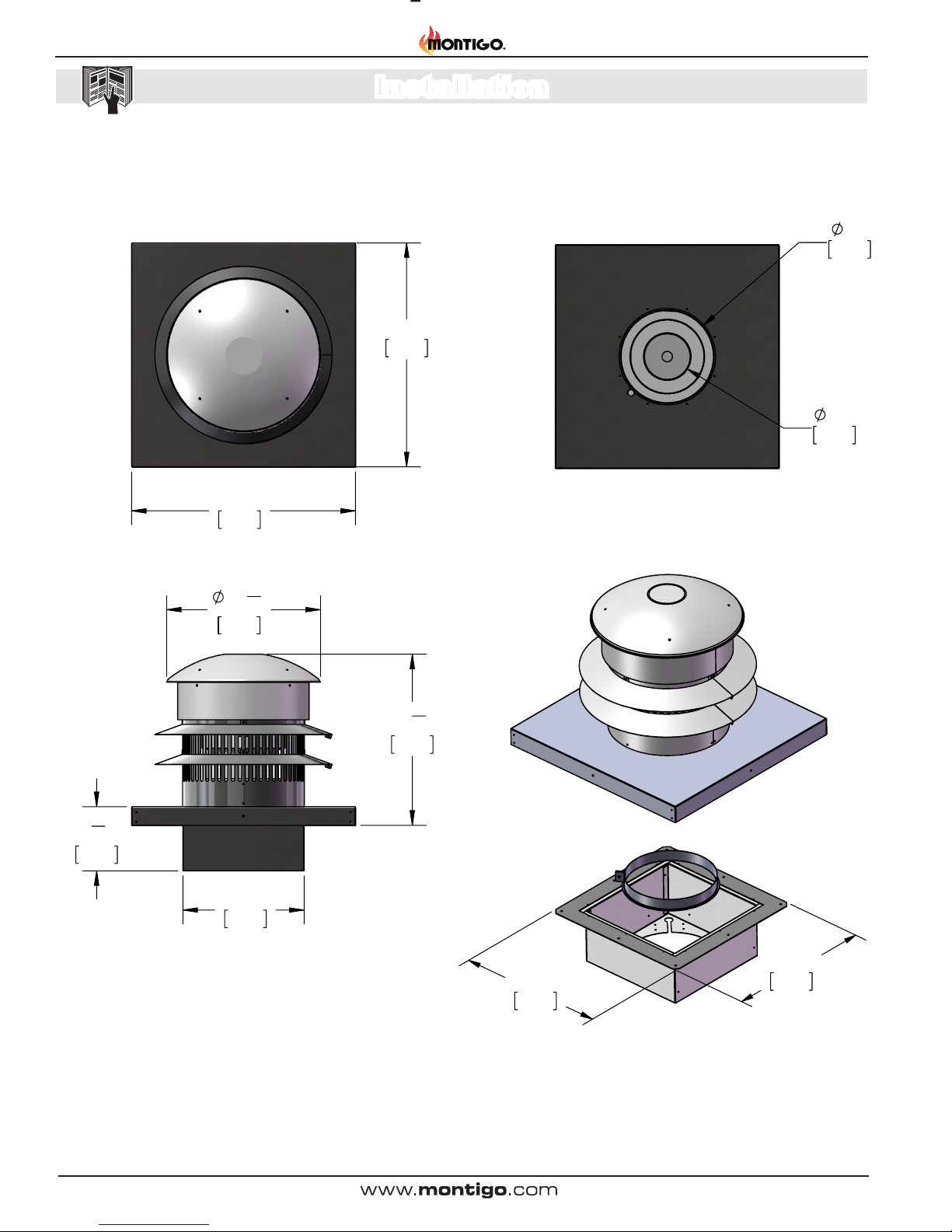
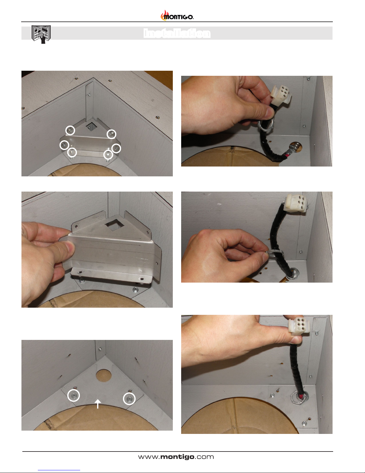
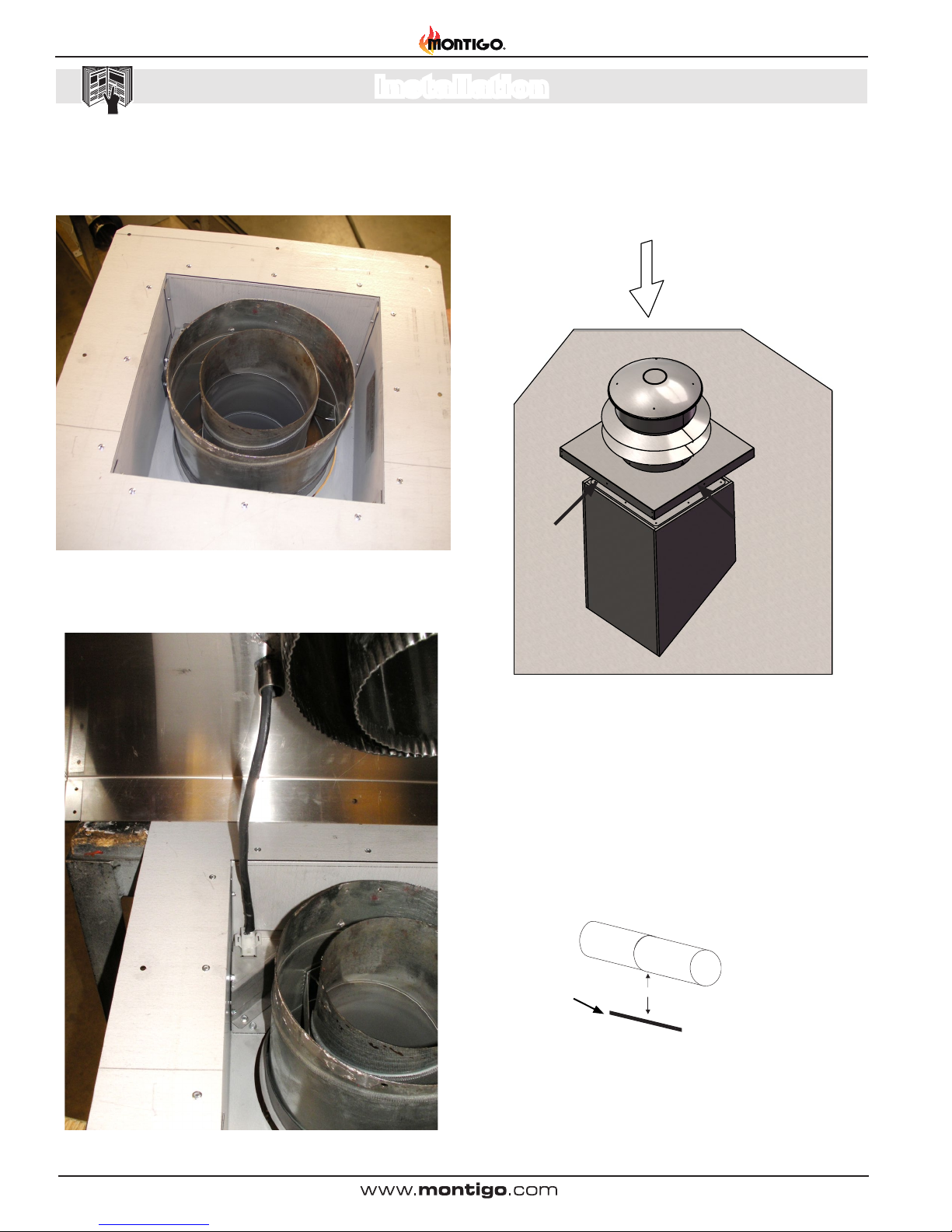
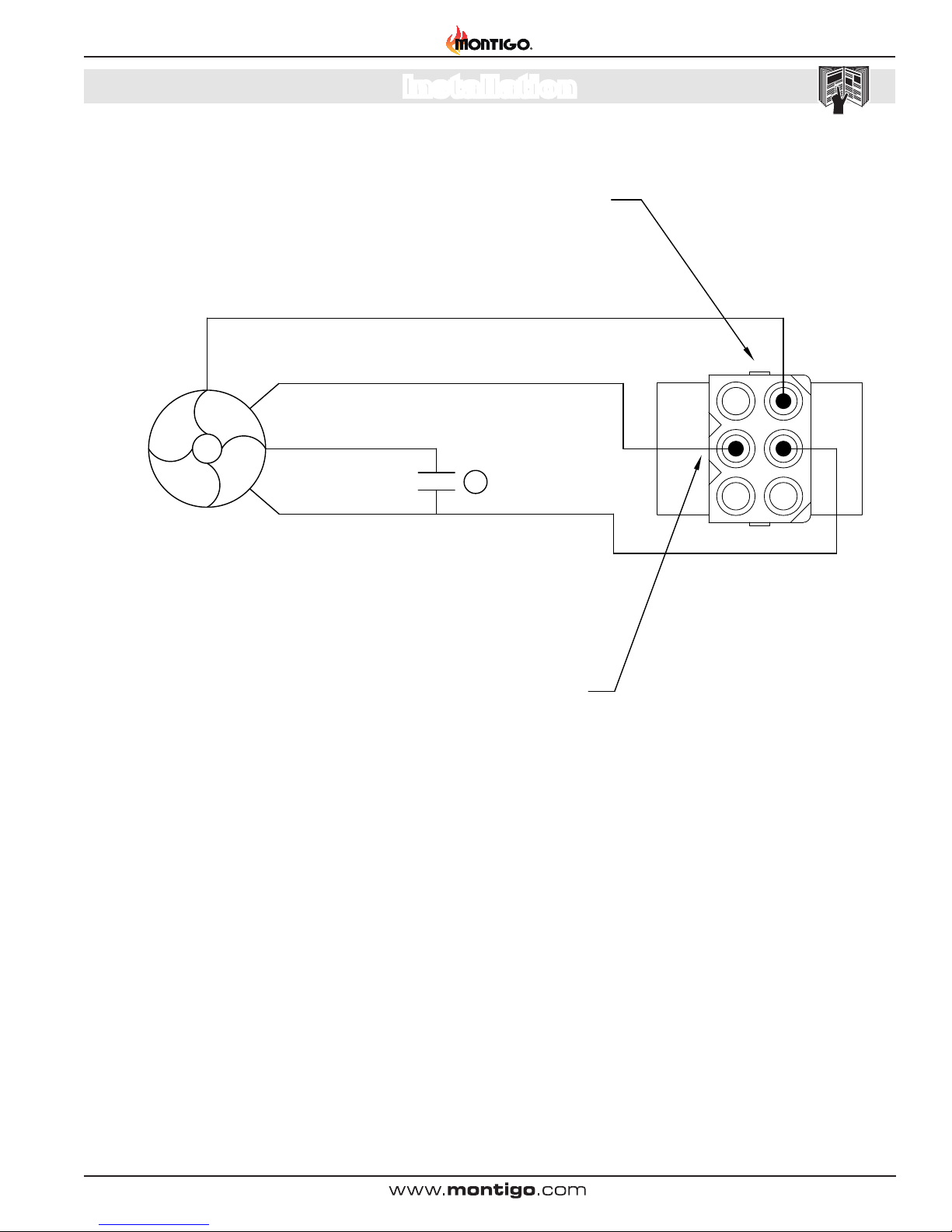
Installation

PVVEX58-300 & PVVEX510-300 Horizontal Power Vent
Page 11
XG0518 - 070714
Top Cover
Top Cover
Screws x 4 plcs
Screw Locations
x 4 plcs
Wind Baffle
Rain Skirt
Screw Locations
x 5 plcs
Top Separator
Step 1:
a) Remove the 4 outer screws
that fasten the Top Cover to
the termination
b) Remove the Cover.
PVVEX58-300
Motor Removal / Servicing
Step 2:
a) Remove the 4 outer screws
that fasten the Wind Baffle to
the termination.
b) Lower the Wind Baffle to
rest on the Rain Skirt.
Step 3:
a) Remove the 5 outer screws
that fasten the Top Separator
to the termination.
b) Remove the Top Separator.
Capacitor Removal and Servicing
Step 1: Remove the 4 outer screws that fasten the top cover to the
termination. Remove the cover.
Figure 5.
Capacitor Replacement [REC1252]
Turn off power and gas before servicing.
Figure 5a.
Step 2: Cut zap straps.
Step 3: Unscrew ground wire/capacitor bracket from motor.
WARNING: Save this screw.
Figure 5b.
Step 4: Cut brown wire from motor and black wire from capacitor.
Figure 5c.
Step 5: Cut black bre wire from power cable and blue wire from
motor.
Figure 5d.
Service

PVVEX58-300 & PVVEX510-300 Horizontal Power Vent
Page 12 XG0518 - 070714
Step 6: Cut white bre from power cable, black wire from capacitor
and black wire from motor.
Figure 5e.
Step 7: Remove and dispose of old capacitor and open REC1252
Figure 5f. REC1252
Step 8: Strip ends of all cut wires and new capacitor. Screw new
capacitor and ground wire to the motor using the existing screw you
saved.
Figure 5g.
Step 9: Using a small bell connector, connect the blue wire from the
motor to the black bre wire from the power cable.
Figure 5h.
Step 10: Using the large bell connector, attach the white bre wire
from the power cable to the black wire from the motor and a black
wire from the capacitor.
Figure 5i.
Step 11: Using the other small bell connector attach the brown wire
from the motor to the other black wire from the capacitor.
Figure 5j.
Service

PVVEX58-300 & PVVEX510-300 Horizontal Power Vent
Page 13
XG0518 - 070714
Step 12: Zap strap wires together in a neat bunch so that no wires
can fall into the motor.
Figure 5k.
Step 13: Zap strap wires to loop in the top of the capacitor.
Figure 5l.
Step 14: Test the power vent and make sure it is working properly.
When looking down at the top of the motor the fan should be spinning
counterclockwise. If it is spinning the wrong way or not at all it is wired
incorrectly. Put the top cover back on using the supplied replacement
screws.
Top Cover
Top Cover
Screws x 4 plcs
Screw Locations
x 4 plcs
Wind Baffle
Rain Skirt
Screw Locations
x 5 plcs
Top Separator
Step 1:
a) Remove the 4 outer screws
that fasten the Top Cover to
the termination
b) Remove the Cover.
PVVEX58-300
Motor Removal / Servicing
Step 2:
a) Remove the 4 outer screws
that fasten the Wind Baffle to
the termination.
b) Lower the Wind Baffle to
rest on the Rain Skirt.
Step 3:
a) Remove the 5 outer screws
that fasten the Top Separator
to the termination.
b) Remove the Top Separator.
Figure 5m.
Service

PVVEX58-300 & PVVEX510-300 Horizontal Power Vent
Page 14 XG0518 - 070714
Top Cover
Top Cover
Screws x 4 plcs
Screw Locations
x 4 plcs
Wind Baffle
Rain Skirt
Screw Locations
x 5 plcs
Top Separator
Step 1:
a) Remove the 4 outer screws
that fasten the Top Cover to
the termination
b) Remove the Cover.
PVVEX58-300
Motor Removal / Servicing
Step 2:
a) Remove the 4 outer screws
that fasten the Wind Baffle to
the termination.
b) Lower the Wind Baffle to
rest on the Rain Skirt.
Step 3:
a) Remove the 5 outer screws
that fasten the Top Separator
to the termination.
b) Remove the Top Separator.
Motor and Capacitor Replacement
Step 1: Remove the 4 outer screws that fasten the top cover to the
termination. Remove the cover.
Figure 6.
[REC 1253]
Turn off power and gas before servicing.
Step 2: Remove the 4 outer screws that fasten the wind bafe to the
termination. Lower the wind bafe to rest on the rain skirt.
Top Cover
Top Cover
Screws x 4 plcs
Screw Locations
x 4 plcs
Wind Baffle
Rain Skirt
Screw Locations
x 5 plcs
Top Separator
Step 1:
a) Remove the 4 outer screws
that fasten the Top Cover to
the termination
b) Remove the Cover.
PVVEX58-300
Motor Removal / Servicing
Step 2:
a) Remove the 4 outer screws
that fasten the Wind Baffle to
the termination.
b) Lower the Wind Baffle to
rest on the Rain Skirt.
Step 3:
a) Remove the 5 outer screws
that fasten the Top Separator
to the termination.
b) Remove the Top Separator.
Figure 6a.
Step 3: Remove the 5 outer screws that fasten the top separator to
the termination. Remove the top separator.
Top Cover
Top Cover
Screws x 4 plcs
Screw Locations
x 4 plcs
Wind Baffle
Rain Skirt
Screw Locations
x 5 plcs
Top Separator
Step 1:
a) Remove the 4 outer screws
that fasten the Top Cover to
the termination
b) Remove the Cover.
PVVEX58-300
Motor Removal / Servicing
Step 2:
a) Remove the 4 outer screws
that fasten the Wind Baffle to
the termination.
b) Lower the Wind Baffle to
rest on the Rain Skirt.
Step 3:
a) Remove the 5 outer screws
that fasten the Top Separator
to the termination.
b) Remove the Top Separator.
Figure 6b.
Step 4: Cut 4 zap straps
Figure 6c.
Step 5: Remove the ground screw holding the ground wire and
capacitor.
Figure 6d.
Step 6: Cut the black bre wire from the power cable.
Figure 6e.
Service

PVVEX58-300 & PVVEX510-300 Horizontal Power Vent
Page 15
XG0518 - 070714
Step 7: Cut the white bre wire from the power cable.
Figure 6f.
Step 8: Remove 4 screws securing the motor mounting plate.
Figure 6g.
Figure 6h.
Step 9: Lift out motor and capacitor.
REC1253
Figure 6i.
Step 10: Drop new motor assembly into the power vent and screw
with supplied 4 screws and star washers. Line up cut out in motor
mounting plate with electrical conduit.
Figure 6j.
Step 11: Remove the ground wire screw from the motor. NOTE:
Save this screw for later.
Figure 6k.
Service

PVVEX58-300 & PVVEX510-300 Horizontal Power Vent
Page 16 XG0518 - 070714
Figure 6l.
Step 12: Using the ground screw, screw the capacitor bracket and
the ground wire to the motor.
Step 13: Strip the ends of all the wires. Using the large bell connec-
tor, connect the white bre wire from the power cable to the black wire
from the motor and one of the black wires from the capacitor.
Figure 6m.
Step 14: Using a small bell connector, connect the black bre wire
from the power cable to the blue wire of the motor.
Figure 6n.
Step 15: Using the other small bell connector, connect the other
black wire from the capacitor to the brown wire from the motor.
Figure 6o.
Step 16: Using a zap strap to bundle the wires neatly together.
Figure 6p.
Step 17: Using another zap strap, secure the bundle to the capacitor.
Figure 6q.
Service

PVVEX58-300 & PVVEX510-300 Horizontal Power Vent
Page 17
XG0518 - 070714
Step 18: Using the last two zap straps secure the wires to the leg of
the motor. Make sure none of the wires can get caught in the motor.
Figure 6r.
Step 19: Reinstall the top separator with 5 supplied screws.
Top Cover
Top Cover
Screws x 4 plcs
Screw Locations
x 4 plcs
Wind Baffle
Rain Skirt
Screw Locations
x 5 plcs
Top Separator
Step 1:
a) Remove the 4 outer screws
that fasten the Top Cover to
the termination
b) Remove the Cover.
PVVEX58-300
Motor Removal / Servicing
Step 2:
a) Remove the 4 outer screws
that fasten the Wind Baffle to
the termination.
b) Lower the Wind Baffle to
rest on the Rain Skirt.
Step 3:
a) Remove the 5 outer screws
that fasten the Top Separator
to the termination.
b) Remove the Top Separator.
Figure 6s.
Step 20: Reinstall the wind bafe with supplied screws.
Top Cover
Top Cover
Screws x 4 plcs
Screw Locations
x 4 plcs
Wind Baffle
Rain Skirt
Screw Locations
x 5 plcs
Top Separator
Step 1:
a) Remove the 4 outer screws
that fasten the Top Cover to
the termination
b) Remove the Cover.
PVVEX58-300
Motor Removal / Servicing
Step 2:
a) Remove the 4 outer screws
that fasten the Wind Baffle to
the termination.
b) Lower the Wind Baffle to
rest on the Rain Skirt.
Step 3:
a) Remove the 5 outer screws
that fasten the Top Separator
to the termination.
b) Remove the Top Separator.
Figure 6t.
Step 21: Test the power vent and make sure it is working properly.
When looking down at the top of the motor the fan should be spinning
counterclockwise. If it is spinning the wrong way or not at all it is wired
incorrectly. Put the top cover back on using the supplied replacement
screws.
Top Cover
Top Cover
Screws x 4 plcs
Screw Locations
x 4 plcs
Wind Baffle
Rain Skirt
Screw Locations
x 5 plcs
Top Separator
Step 1:
a) Remove the 4 outer screws
that fasten the Top Cover to
the termination
b) Remove the Cover.
PVVEX58-300
Motor Removal / Servicing
Step 2:
a) Remove the 4 outer screws
that fasten the Wind Baffle to
the termination.
b) Lower the Wind Baffle to
rest on the Rain Skirt.
Step 3:
a) Remove the 5 outer screws
that fasten the Top Separator
to the termination.
b) Remove the Top Separator.
Figure 6u.
Service

PVVEX58-300 & PVVEX510-300 Horizontal Power Vent
Page 18 XG0518 - 070714
Appendix
Appendix A: Warranty
The Warranty
The Companies warrants the Montigo Gas Appliance to be free from defects in materials and workmanship at the time of manufacture. On the Montigo replace,
there is a ten-year warranty on the rebox and its components, a ve-year warranty on the main burner and pilot burner, and a one-year warranty on the gas control
valve, bre logs and Power Vent Module. The Glass, plated / painted nishes, and refractory lining are exempt from the warranty.
Remedy And Exclusions
The coverage of this Warranty is limited to all components of the Gas Appliance manufactured by The Companies.
This Warranty only covers Montigo Gas Appliances installed in the United States or Canada.
If the components of the Gas Appliance covered by this Warranty are found to be defective within the time frame stated (see The Companies right of investigation
outlined below). The Companies will, at its option, replace or repair defective components of the Gas Appliance manufactured by The Companies at no charge,
and will also pay for reasonable labour costs incurred in replacing or repairing components. If repair or replacement is not commercially practical, The Companies
will, at its option, refund the purchase price of the Montigo Gas Appliance.
This Warranty covers only parts and labour as provided above. In no case shall The Companies be responsible for materials, components, or construction which
are not manufactured or supplied by The Companies, or for the labour necessary to install, repair or remove such materials, components or construction. All
replacement or repair components will be shipped F.O.B. the nearest The Companies factory.
Qualications To The Warranty
The Gas Appliance Warranty outlined above is further subject to the following qualications:
(1) The Gas Appliance must be installed in accordance with The Companies installation instructions and local building codes. The Warranty on this Montigo
Gas Appliance covers only the component parts manufactured by The Companies. The use of components manufactured by others with this Montigo Gas
Appliance could create serious safety hazards, may result in the denial of certication by recognized national safety agencies, and could be in violation of
local building codes. This warranty does not cover any damages occurring from the use of any components not manufactured or supplied by The Companies
(2) The Montigo Gas Appliance must be subjected to normal use. The Gas Appliances are designed to burn gas only. Burning conventional replace fuels such
as wood, coal or any other solid fuel will cause damage to the Gas Appliance, will produce excessive temperatures and will result in a re hazard.
Limitations On Liability
It is expressly agreed and understood that The Companies sole obligation, and purchaser's exclusive remedy under this Warranty, under any other warranty,
expressed or implied, or in contract, tort or otherwise, shall be limited to replacement, repair, or refund, as specied above.
In no event shall The Companies be responsible for any incidental or consequential damages caused by defects in its products, whether such damage occurs
or is discovered before or after replacement or repair, and whether or not such damage is caused by The Companies negligence. Some states do not allow the
exclusion or limitation of incidental or consequential damages, so the above limitation or exclusion may not apply to you. The duration of any implied warranty
with respect to this Montigo Gas Appliance is limited to the duration of the foregoing warranty. Some states do not allow limitation on how long an implied warranty
lasts, so the above may not apply to you.
Investigation Of Claims Against Warranty
The Companies reserves the right to investigate any and all claims against this Warranty and to decide upon method of settlement.
The Companies Are Not Responsible For Work Done Without Written Consent
The Companies shall in no event be responsible for any warranty work done without rst obtaining The Companies written consent.
Dealers Have No Authority To Alter This Warranty
The Companies employees and dealers have no authority to make any warranties nor to authorize any remedies in addition to or inconsistent with those stated above.
How To Register A Claim Against Warranty
In order for any claim under this Warranty to be valid, The Companies must be notied of the claimed defect in writing or by telephone, as soon as reasonably
possible after the defect is discovered. Claims against this Warranty in writing should include the date of installation, and a description of the defect.
Other Rights
This Warranty gives you specic legal rights, and you may also have other rights which vary from state to state.
NOTE: The Companies as stated above refer to - Canadian Heating Products Inc. and/or Montigo Del Ray Corp.
Canadian Heating Products Inc. and/or Montigo DelRay Corp. reserves the right to make changes at any time, without notice, in design, materials,
specications, prices and also to discontinue colors, styles and products.

PVVEX58-300 & PVVEX510-300 Horizontal Power Vent
Page 19
XG0518 - 070714
Appendix
Appendix B: State of Massachusetts
Amendment
(Gas Fireplace / Equipment sold in the State of Massachusetts)
5.08: Modications to NFPA-54, Chapter 10
(1) Revise NFPA-54 section 10.5.4.2 by adding a second exception as follows:
Existing chimneys shall be permitted to have their use continued when a gas conversion burner is installed, and shall be equipped with a manually reset device
that will automatically shut off the gas to the burner in the event of a sustained back-draft.
(2) Revise 10.8.3 by adding the following additional requirements:
(a) For all side wall horizontally vented gas fueled equipment installed in every dwelling, building or structure used in whole or in part for residential purposes,
including those owned or operated by the Commonwealth and where the side wall exhaust vent termination is less than seven (7) feet above nished grade in
the area of the venting, including but not limited to decks and porches, the following requirements shall be satised:
1. INSTALLATION OF CARBON MONOXIDE DETECTORS. At the time of installation of the side wall horizontal vented gas fueled equip-
ment, the installing plumber or gas tter shall observe that a hard wired carbon monoxide detector with an alarm and battery back-up is installed on the oor
level where the gas equipment is to be installed. In addition, the installing plumber or gas tter shall observe that a battery operated or hard wired carbon
monoxide detector with an alarm is installed on each additional level of the dwelling, building or structure served by the side wall horizontal vented gas fueled
equipment. It shall be the responsibility of the property owner to secure the services of qualied licensed professionals for the installation of hard wired carbon
monoxide detectors
a. In the event that the side wall horizontally vented gas fueled equipment is installed in a crawl space or an attic, the hard wired carbon monoxide detector with
alarm and battery back-up may be installed on the next adjacent oor level.
b. In the event that the requirements of this subdivision can not be met at the time of completion of installation, the owner shall have a period of thirty (30) days
to comply with the above requirements; provided, however, that during said thirty (30) day period, a battery operated carbon monoxide detector with an alarm
shall be installed.
2. APPROVED CARBON MONOXIDE DETECTORS. Each carbon monoxide detector as required in accordance with the above provisions
shall comply with NFPA 720 and be ANSI/UL 2034 listed and IAS certied.
3. SIGNAGE. A metal or plastic identication plate shall be permanently mounted to the exterior of the building at a minimum height of eight (8) feet
above grade directly in line with the exhaust vent terminal for the horizontally vented gas fueled heating appliance or equipment. The sign shall read, in print
size no less than one-half (1/2) inch in size, “GAS VENT DIRECTLY BELOW. KEEP CLEAR OF ALL OBSTRUCTIONS”.
4. INSPECTION. The state or local gas inspector of the side wall horizontally vented gas fueled equipment shall not approve the installation unless,
upon inspection, the inspector observes carbon monoxide detectors and signage installed in accordance with the provisions of 248 CMR 5.08(2)(a)1 through 4.
(b) EXEMPTIONS: The following equipment is exempt from 248 CMR 5.08(2)(a)1 through 4:
1. The equipment listed in Chapter 10 entitled “Equipment Not Required To Be Vented” in the most current edition of NFPA 54 as adopted by the
Board; and
2. Product Approved side wall horizontally vented gas fueled equipment installed in a room or structure separate from the dwelling, building or struc-
ture used in whole or in part for residential purposes.
(c) MANUFACTURER REQUIREMENTS - GAS EQUIPMENT VENTING SYSTEM PROVIDED. When the manufacturer of Product
Approved side wall horizontally vented gas equipment provides a venting system design or venting system components with the equipment, the instructions
provided by the manufacturer for installation of the equipment and the venting system shall include:
1. Detailed instructions for the installation of the venting system design or the venting system components; and
2. A complete parts list for the venting system design or venting system.
(d) MANUFACTURER REQUIREMENTS - GAS EQUIPMENT VENTING SYSTEM NOT PROVIDED. When the manufacturer of a Prod-
uct Approved side wall horizontally vented gas fueled equipment does not provide the parts for venting the ue gases, but identies “special venting systems”,
the following requirements shall be satised by the manufacturer:
1. The referenced “special venting system” instructions shall be included with the appliance or equipment installation instructions; and
2. The “special venting systems” shall be Product Approved by the Board, and the instructions for that system shall include a parts list and
detailed installation instructions.
(e) A copy of all installation instructions for all Product Approved side wall horizontally vented gas fueled equipment, all venting instructions, all parts lists for
venting instructions, and/or all venting design instructions shall remain with the appliance or equipment at the completion of the installation.
(3) After NFPA-54 section 10.10.4.2 add a new section 10.10.4.3 as follows:
When more than four gas appliances are to be vented through a common gas vent or common horizontal vent manifold, a plan of the proposed vent installation
shall be submitted to the Inspector and the serving gas supplier for review and approval.
Extraction from: Massachusetts Rules and Regulations
5.00: Amendments To 2002 Edition Of ANSI Z223.1-NFPA-54

Ferndale, Washington
TF: 1.800.789.6236
FX: 1.866.3000.0927
XG0518 - 070714
Langley, British Columbia
TF: 1.800.378.3115
FX: 1.604.607.6462
PVVEX58-300 & PV-
VEX510-300
Power Vent Termination
This manual suits for next models
1
Table of contents
Other Montigo Ventilation Hood manuals
Popular Ventilation Hood manuals by other brands

Bellini
Bellini CRHR6W01 Installation and user manual

Franke
Franke FNO 605 BK user manual

Franke
Franke OPAL FRI 772-10 User instructions

Futuro Futuro
Futuro Futuro MURANO Instruction booklet

UTEK
UTEK DEH GUIDE FOR INSTALLATION, USE AND MAINTENANCE

KOBE
KOBE CH3830SQB-1 Installation instructions and operation manual