MONTREL TECNOLOGIA ADR Multi 4000 User manual

OPERATION
MANUAL
ANDROID VERSION
ADR Multi
4000
®

SAFETY INFORMATION – READ FIRST
Preventing electric shock:
• Please read carefully the entire manual before using your ADR and its
accessories;
• Do not operate your ADR Multi 4000 in the rain;
• Do not open your ADR Multi 4000 when energized;
• Use only insulated accessories indicated for the ADR Multi 4000;
• Do not apply input voltages above the ADR Multi
• 4000 rating;
• Before using, inspect the ADR Multi 4000 cabinet, the testing tips, and
the accessories for damages, and replace them as needed;
• Use of the equipment in a manner not specied in the operation
manual and safety standards will result in malfunctioning and/or risk
to the operator.
Symbols Utilized:
See explanation in the manual;
Alternate current;
Pulses;
Equipment protected by double insulation or reinforced;
Disposing of the device - All products containing this symbol must be
disposed of separately from regular household residues, as per the
local environmental legislation. If you cannot nd safe information,
please contact our technical assistance at +55 19 3861 3070 or on
our website: www.montrel.com.br.
*The pattern of colors - red, black, yellow, blue - and the name of the phases - A, B, C, N -
adopted in this manual were chosen arbitrarily.
The meaning of each phase is as follows:
A= R, L1, U
B= S, L2, V
C= T, L3, W
N=Neutral
Colors may vary on demand.

Summary
1 - Quick Guide �����������������������������������������������������������������������������������������������������������������4
2 - introduction ���������������������������������������������������������������������������������������������������������������5
3 - ApplicAtions ����������������������������������������������������������������������������������������������������������������5
4 - technicAl feAtures ������������������������������������������������������������������������������������������������������5
5 - hAndlinG cAre �������������������������������������������������������������������������������������������������������������6
6 - storAGe And operAtion ����������������������������������������������������������������������������������������������7
7 - MeAsured electric QuAntities �������������������������������������������������������������������������������������7
8 - GettinG to know your device ��������������������������������������������������������������������������������������8
8�1 - operAtion options �������������������������������������������������������������������������������������������12
9 - connection systeM ���������������������������������������������������������������������������������������������������14
10 - feAtures ������������������������������������������������������������������������������������������������������������������19
10�1 - stArt ��������������������������������������������������������������������������������������������������������������20
10�2 - Adr ����������������������������������������������������������������������������������������������������������������21
10�3 - relAtórios�������������������������������������������������������������������������������������������������������27
10�4 - reports ����������������������������������������������������������������������������������������������������������28
10�5 - help ���������������������������������������������������������������������������������������������������������������29
10�6 - settinGs ����������������������������������������������������������������������������������������������������������29
10�6�1 - GenerAl �������������������������������������������������������������������������������������������������29
10�6�2 - pArAMeters ��������������������������������������������������������������������������������������������30
10�6�3 - Modules ������������������������������������������������������������������������������������������������32
10�6�4 - connection �������������������������������������������������������������������������������������������40
10�6�5 - profile ���������������������������������������������������������������������������������������������������41
10�6�6 - user ������������������������������������������������������������������������������������������������������42
10�7 - exit �����������������������������������������������������������������������������������������������������������������43
11 - Accessories �������������������������������������������������������������������������������������������������������������44
12 - wArrAnty certificAte ..............................................................................................45
Operation Manual
Model: Multi 4000
Android Version
Rev. 6
Req. Pat.

4
ADR MULTI4000
1 - QUICK GUIDE
Step-by-step use of ADR Multi 4000 to check
energy meters:
1. Connect external trigger to ADR Multi 4000 (Item 4, page 10);
2. Connect current clamps to ADR Multi 4000 (Item 5, page 11);
3. Connect power supply cables to ADR Multi 4000 (Item 6, page 11);
4. Connect ADR Multi 4000 to installation according to the type of connection found
(details on page 14);
5. Check if status LED is signaling that ADR Multi 4000 is properly energized (item 2,
page 09);
6. Turn on tablet and access ADR Multi 4000 application providing your user name
and password (details on page 19 and 20);
7. Access the “ADR” function and wait for connection (details on page 21);
8. Fill out data on test setup screen according to the type of energy meter found and
click on "next" (details on page 21);
9. Browse through the screens until reaching the phasor diagram and check if the
observed phase shifts are correct (details on page 25);
10. Press “Enable” (details on page 26);
11. When going through reference, the rst disk mark or pulse, press the external
trigger button or press the “Pulse” button displayed on the tablet or smartphone
screen and start counting;
12. When counting reaches the number of desired turns, press again the trigger but-
ton or the “Pulse” button displayed in the tablet screen to nish the test (when the
type of counting selected is “start and end”);
13. When identifying the end of the test, the application will display the test results
obtained and and the option to save the test (details on page 26);
14. After saving the test, it will be available for queries and printing on the report
screen (details on page 27).

5
2 - INTRODUCTION
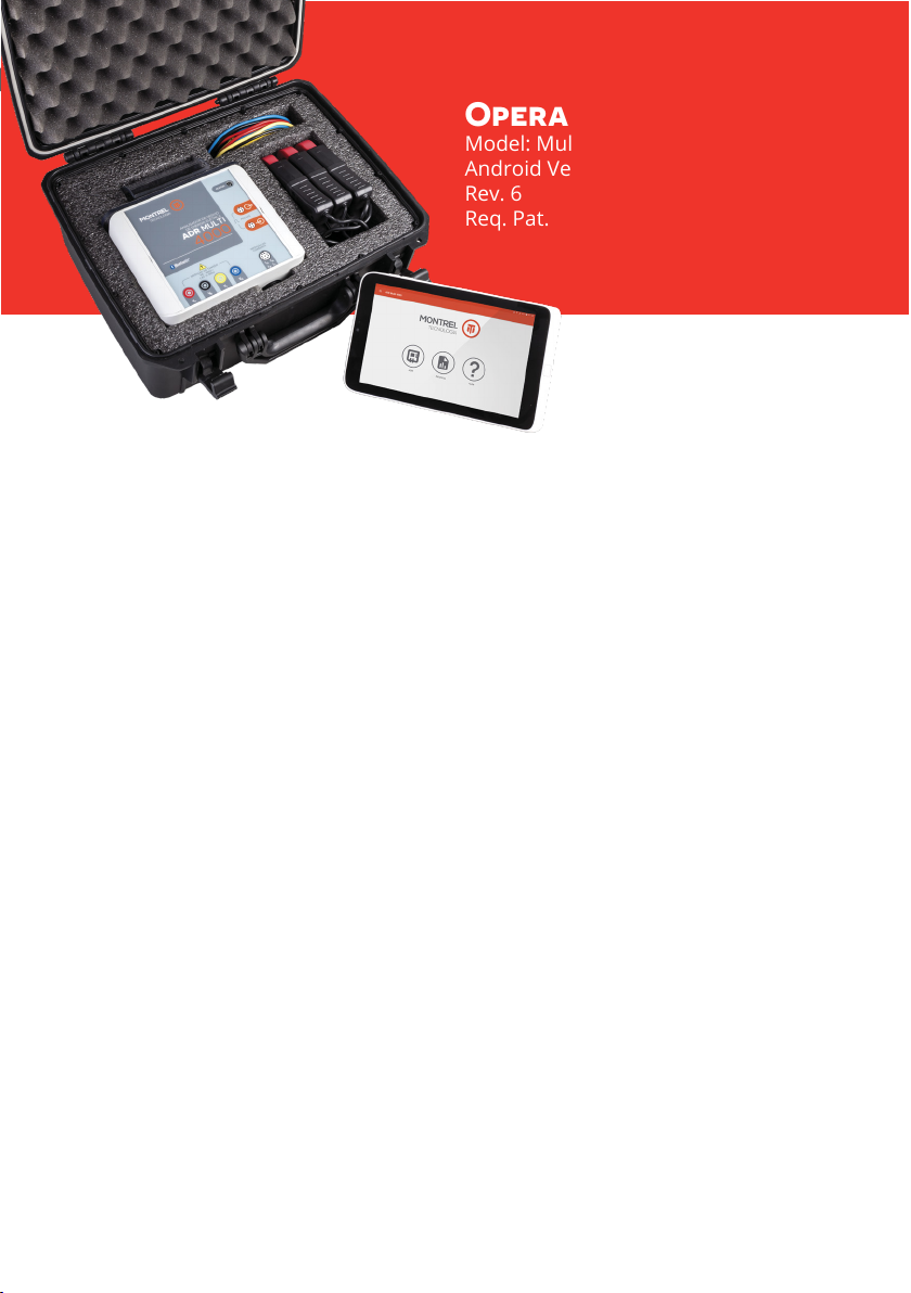
ADR Multi 4000 is a portable electronic analyzer for electric energy registering,
which is capable of identifying deviations in the consumption of electromechanical
or electronic gauges, providing eld technicians a reliable tool in making a decision
regarding the need for replacing the power meter or submit it for calibration in a
laboratory. Through metering using CTs, such as clamps with articulated or exible
core and without the need to turn o consumer’s electric network (as it uses the
client’s own load), ADR Multi 4000 can be connected to the power power meter in
the electric meter box or the client’s input extension and is operated via Bluetooth
communication with a mobile device, such as a Tablet or Smartphone. The device
is capable of checking power meter and the installation, in addition to identifying
consumption deviations in a practical and ecient manner.
3 - APPLICATIONS
• Analysis of consumption deviation in electric power meters;
• Analysis of energy deviation in the client’s input extensions using the
• comparison;
• Method – input extension connection;
• Electrical quantities metering – portable multi-meter;
• Graphic visualization of electric values;
• Testing report with inspection receipt;
• Inspection at the request of the client or due to suspected irregularity;
• Metering campaigns;
• Testing client’s during cutting or reconnection.
4 - TECHNICAL FEATURES
• Switched-mode power supply;
• Supplied by the metering connection itself;
• Power supply: 90 to 480 V~ ± 10% (Ph-Ph) and 90 to 280 V~ ± 10% (Ph-N) ;
• Operating frequency: 45 to 65 Hz;
• Maximum consumption: 10 W;
• Minimum power supply eciency: 75%;
• Protection: Fuse F 0.5A 630 V~;
• Voltage metering range: 80 to 530V~;
• Measuring impedance: 1.5MΩ;
• Supply connection: safety terminal 4mm;
• Electric insulation: CAT IV – 600 V~;
• Current metering range: 1 to 3000A (Other scales upon request);
• Clamp type: Articularted core;
• Current connection: Connector M24x9;
• Calibration pulse outputs Wh and varh in male connector M8 x 4;
• Pulse input of sensor / manual trigger in female connector M8 x 4;
• Auxiliary output voltage: 12 V @ 100 mA;
• Maximum frequency MSM4000 : 100 Hz;

6
ADR MULTI4000
• Maximum frequency MSP4000 : 100 Hz;
• STATUS indication LED;
• Maximum operating temperature: 60 °C;
• Dimensions: 180 x 150 x 60 mm;
• Weight: <1 kg;
• Casing: ASA+PC;
• Ingress Protection code: IP65;
• Connectivity: Bluetooth Connection - Class 2 (20 meters);
• Accuracy class*:
• Metering method: Integration by reference;
• Remote operation: Tablet or Smartphone with Bluetooth communication;
• Operating system: Android® 4.1 or higher;
• Support for eld printing;
• Graphic visualization of electric values;
• Data inserted by client / operator;
• Report on the results obtained;
• Data saved in ".csv", ".html", or ".pdf";
• Sharing of results (email or database).
*Maximum error [%] = Accuracy class / Power factor:.
5 - HANDLING CARE
It is imperative to read the operation manual before installing and using ADR Multi
4000. If you have any questions, please call our technical support at: +55 19 3861
Preventive maintenance of the devices is unnecessary. Corrective maintenance, if
necessary, must be provided by Montrel Controles Eletrônicos Ltda. qualied tech-
nicians, by shipping the defective part to our factory, or by other technicians previ-
ously approved by Montrel. The device and its accessories can only be cleaned on
the outer surfaces, using a neutral product and with the device de-energized. In the
articulated clamp, the “gap” must be cleaned with liquid silicone to protect it against
oxidation. A low battery charge in the control device (tablet or smartphone) may
compromise device operation.
NOTE: Failure to clean the clamp may compromise device accuracy.
Wh ≤ 0.2%, varh ≤ 0,4% (2.5A ≤ current ≤ 200A; clamp 200A)
Wh ≤ 0.5%, varh ≤ 1,0% (1.0A ≤ current < 2.5A; clamp 200A)
Wh ≤ 0.2%, varh ≤ 0,4% (0.25A ≤ current ≤ 10A; clamp 10A)
Wh ≤ 0.5%, varh ≤ 1,0% (0.1A ≤ current < 0.25A; clamp 10A)

7
ADR Multi 4000 installation, parametrization, and operation must only be
made by qualied technicians who are fully aware of and thoroughly under-
stand the content of the Operation Manual. All connections must be made
with total care by technicians qualied to perform services in energized
electric systems and using personal protection equipment (PPE) and collec-
tive protection equipment (CPE) in accordance with the applicable rules and
proper instructions. Do not operate the device in conditions or situations not
provided for in this manual. If you have any questions, please call our Techni-
cal Support at +55 19 3861 3070 or send an email to [email protected].
6 - STORAGE AND OPERATION
• Transportation temperature and storage: -25 to 70°C;
• Relative humidity: 10 to 90%;
• Altitude: up to 2000m;
• Degree of pollution 3;
• Temperature coecient: 50ppm / °C;
• Do not operate out of specications;
• For external use, but not to be operated in the rain;
• Maximum pile: 3 devices in original packaging.
7 - MEASURED ELECTRIC QUANTITIES
• Single-phase, Two-phase, and Three-phase metering;
• RMS voltage;
• RMS current;
• Active power;
• Reactive power;
• Apparent power;
• Power factor;
• Phase angle;
• Active energy;
• Reactive energy.
WARNING

8
ADR MULTI4000
8 - GETTING TO KNOW YOUR DEVICE
ADR Multi 4000 is operated by a dedicated application installed in an Android® de-
vice version 4.1 or higher. A Tablet or Smartphone can be utilized for this operation.
As an example, this manual will address use and operation indication in a Smart-
phone, though without losses or changes for operation by other devices. Figure 8-1
shows the application screen in a tablet and a smartphone.
Figure 8-1 Operation screen.
Figure 8-2 ADR Multi 4000 Overview.
Figure 8-2 shows an overview of ADR Multi 4000 indicating the details.
Fixing and protection support;
Status LED;
Pulse output connection;
Pulse input connection;
Current clamp connection;
Voltage connection terminals.
1
2
3
4
5
6

9
1
2
1
2
As seen in item , the polycarbonate xing and protection support ensures protec-
tion against impact on the device and oers several types of xing support. Compris-
ing a mobile and adjustable strap, it can be used hanging on the client’s input exten-
sion when the strap is positioned forward, or hanging on a panel door or the edge of a
gauging box if the strap is facing backwards. More details in gure 8-3, where shows
the assembly for hanging it on the input extension and shows the assembly for xing
it to a panel door or the edge of a meter box.
1 2
Figure 8-3 Fixing support details.
Figura 8-4 Fixing support lock details.
Figure 8-4 shows the back of ADR Multi 4000 and details the adjustment of the xing
strap.
In item and, in detail, gure 8-5, the LED indicates the operation condition of ADR
Multi 4000. Table 8-1 shows the possible conditions in the status indication.

10
ADR MULTI4000
Table 8-1 STATUS Indication.
Table 8-2 Pulse output connector.
Figure 8-5 STATUS Indication.
Figure 8-6 Pulse output.
Status Indication
M8 x 4 male pulse output connector
Number
Pin
Status
Out-
Descrip-
Cong. 1 Cong. 2 Cong. 3
1
1
O
S1
Device de-energized
P1 [kWh] Q1 [kvarh] PΣ [kWh]
QΣ [kvarh]
-
-
Q2 [kvarh]
Q3 [kvarh]
-
P2 [kWh]
P3 [kWh]
-
Disconnected and energized
Disconnected and Faulty
Connected and energized
Connected and Faulty
O + 1 Pulse
S2
O + 2 Pulses
S3
On + 1 Pulse
Common
On + 2 Pulses
2
2
3
3
4
4
5
The terms 'disconnected' and 'connected' in table 8-1 regard Bluetooth communication
between ADR Multi 4000 and its controlling device, in this case, the Smartphone.
In the case of the pulse output connector in item 3, the main characteristic is the open
collector type opto-coupled signals. These signals have a rate of 360,000 impulses/kWh
or kvarh to the set of 200A clamps and a rate of 7,200,000 impulses/kWh or kvarh to the
set of 10A clamps, congurable to facilitate ADR Multi 4000 calibration. Table 8-2 shows
the electric functions of the output connector pins; and gure 8-6 shows the mechanical
display and characteristics of the connector. More details on calibration can be found in
section 10.4.
Should it be necessary to perform the calibration procedure, please contact the Montrel
technical team for further information.
Item shows the pulse input connection utilized for capturing pulses that indicate
the kWh or kvarh of electromechanical or electronic meters; these pulses may arise
from the external trigger, calibration or sensor standards, within the maximum fre-
quency of 100Hz. In the pulse input connector is available an auxiliary voltage out-
put of 12V @ 100mA, utilized, for instance, to supply the sensor. The input signal
may thus be of the dry contact type, NPN type, PNP type or the TTL logical signal type
and depends on the selected closing setting. Table 8-3 shows the electric function of
4

11
Table 8-3 Pulse input connector.
Table 8-4 Current input connector.
Figure 8-7 Pulse input connector.
M8 x 4 female pulse input connector
M24 x 9 Female Connector
Pin
Pin
Function
Function
1
1
+12V
Phase A Current
Phase A Current’
Phase B Current
Phase C Current
Phase B Current’
Phase C Current’
Neutral Current
Neutral Current’
Shield
Cathode
Anode
0V
2
2
3
3
4
4
5
6
7
8
9
6
each pin in the connector and gure 8-7 shows the mechanical display of the pins
and the characteristics of the external trigger and pulse input connector. pino do
Item , shows the input of signals from the current clamps. It is possible to connect
up to four clamps, to measure the current in phases A, B, C, and Neutral. Table 8-4
shows the electric function of the pins and gure 8-8 shows the mechanical display
and characteristics of the connector.
Figure 8-8 Current input connector.
Finally, item shows the connection of the voltage metering and power supply
cables. Table 8-5 lists the color sequence and the respective functions of the 4-mm
safety terminals, and gure 8-9 shows heir details and display.
5

ADR MULTI4000
12
Table 8-5 Voltage input terminals. Figure 8-9 Voltage input terminals.
4-mm safety terminals
Terminal Function
Red
Black
Yellow
Blue
Phase A voltage input
Phase B voltage input
Phase C voltage input
Neutral reference input
8.1 - OPERATION OPTIONS
According to the need and application, it is possible to choose some options that fa-
cilitate and further enhance device performance. If you have any questions send an
may be provided according to the need and upon business proposal.
Voltage signal connection uses the crocodile clips seen in gure 8-10.
Figure 8-10 Voltage Connections.
Figure 8-11 Articulated core current metering clamp.
For current metering, it is possible to choose, upon acquisition of the device, the ar-
ticulated core clamps seen in gure 8-11, or the exible clamps seen in gure 8-12.
In both cases, it is necessary to check availability for the maximum desired current
and the work range.
Note: Maintain the closure point of the articulate clamp (gap) clear of impurities and
oxidation to avoid compromising device accuracy.
Figure 8-12 Flexible current clamp.
(UNDER REQUEST)

13
Figure 8-13 Mark or pulse sensor - MSM 4000.
Figure 8-14 Infrared pulse sensor - MSP 4000.
Figure 8-15 External trigger - MDE 4000.
Meter pulses can be captured in three optional manners: in the rst option, we
have the MSM 4000 sensors for automatic pulse capturing for electromechanical or
electronic meters, in which the sensor is xed to the front part of the meter through
suction cups, and can detect the disk mark or the LED pulse; this sensor is shown in
gure 8-13; in the second option, should it be necessary to capture infrared pulses
through the programming port of electronic gauges, it is possible to use the infrared
pulse sensor,
model MSP 4000, shown in gure 8-14. Finally, in the third option, for manual oper-
ation, it is possible to choose the external trigger, model MDE 4000, shown in gure
8-15.

14
ADR MULTI4000
Other options oered are the calibration pulse output cable shown in gure 8-16
and the storage and transportation case for use without disconnecting the cables at
each test, shown in gure 8-17.
Figure 8-16 Calibration pulse
output cable.
Figure 8-17 Transport and storage case.
9 - CONNECTION SYSTEM
ADR Multi 4000 is simply a meter of multiple electric quantities, for use in electric
power distribution systems. As a basic operation principle, we have the collection
of information on electric quantities by metering the voltage and electric current in
the circuit and the subsequent calculation of the related values, such as the ener-
gy consumed and the power, among others that are indispensable to inspection,
quality control and identication of failures and issues in electric power distribution
systems. Therefore, the entire analysis is made connecting the device to the voltage
and current line of the meter under testing with the help of appropriate accessories
like crocodile clips and articulated clamps (current transducer).
As mentioned above, ADR Multi 4000 is supplied through the voltage connection it-
self, without generating signicant distortions in the gauging of electric parameters.
The most common types of connection to connect ADR Multi 4000 are shown in
gures 9.1 to 9.8. Be mindful of the correct
connection and the phase sequence between the voltage connection and the elec-
tric current.

15
A - Single-phase connection – 1 Phase + Neutral + 1 CT.
B - Two-phase connection – 2 Phases + Neutral + 2 CTs or
1 Phase 3 Wires.
Figure 9-1 Single-phase connection system.
Figure 9-2 Two-phase connection.

16
ADR MULTI4000
C - Balanced three-phase connection – 1 Phase + Neutral + 1 CT.
D - Three-phase connection without neutral – 3 Phases + 2 CTs
Figure 9-3 Balanced three-phase connection.
Figure 9-4 Three-phase connection without neutral with 2 CTs.

17
E - Three-phase connection without neutral – 3 Phases + 3 CTs.
F - Three-phase connection – 3 Phases + Neutral + 3 CTs.
Figure 9-5 Three-phase connection without neutral with 3 CTs.
Figure 9-6 Three phase connection.

18
ADR MULTI4000
G - Indirect three phase connection – 3 Phases + Neutral + 3 CTs.
H - Indirect three phase connection - 3 Phases + 2CTs.
Figure 9-7 Indirect three phase connection.
Figure 9-8 Indirect three phase connection 2 elements.

19
Figure 10-1 Login
In all cases above, be mindful of the color sequence to ensure correct metering, and
check for a possible inversion in the direction of the current clamps.
If the clamps have arrows indicating the direction of the current, connection must
be made so that the direction of the arrow indicates the side of the load in the
installation. If the parameter indications and reading are not coherent, e.g., if they
are indicating negative values or extremely high phase shifts, review connections in
order to identify any possible inversion.
The neutral current clamp is optional, serving as an indication of the actual value of
the current in the neutral conductor. Therefore, the energy parameters, as well as
powers, do not take this parameter into account.
10 - FEATURES
This chapter addresses operation of the ADR
Multi 4000 device using the application operated
by a Smartphone with Android® operating sys-
tem, example in this manual, with the possibil-
ity of minor changes in the screen layout when
the device used is a Tablet; due to the necessary
screen resizing to display all information
without losses to the operation.
To start using it, the application must be opened
by clicking the ADR Multi 4000 icon in your An-
droid® device. A login screen is presented,and
then, the elds user and password are request-
ed. Figure 10-1 shows the login screen.

20
ADR MULTI4000
Figure 10-3 Side Menu Screen.
The other available functions are listed in the
side menu that is displayed by horizontally
swiping your nger on the screen from left to
right, starting on the left side of the screen,
or by clicking on the “Start” icon on the upper
left corner.Using the side menu, it is possible
to browse through the ADR Multi 4000 func-
tionalities, such as Parameters and Modules,
among others. Figure 10-3 shows the screen
containing the side menu.
All options available in the side menu are de-
tailed below.
10.1 - START
On the start screen, the user has access to the “ADR” functionality, in which tests
are conducted in the power meters, has access to the “Reports”saved in the device
and to the “Help” module, which enables the user to refer to the operation manual
of the device.
After accessing the application providing
the user and password*, the main screen is
displayed containing the icons of the main
functionalities, which are, ADR, REPORTS, and
HELP, which can be accessed by directly click-
ing on the icon. The functionalities described
in the manual do not need to be accessed
according to the sequence shown, and there-
fore, can be run as necessary. Figure 10-2
shows the main screen containing the appli-
cation functions.
Figure 10-2 Start Screen.
* When opening the application for the rst time, type in
‘montrel’ for user and ‘montrel’ for password. After access-
ing the application, this information can be removed and
new users can be created.
Table of contents
Popular Measuring Instrument manuals by other brands

Kikusui
Kikusui KJM6335 Operation manual

Triplett
Triplett SoniChek PRO 3550 instruction manual

Analog Devices
Analog Devices ADXL180 iMEMS manual

DH Instruments
DH Instruments RPM3 - VERSION 2002 Operation and maintenance manual

LaserLiner
LaserLiner LaserCube manual

Connective Peripherals
Connective Peripherals EasyScopeIII user guide