Moog Tritech Micron Echosounder User manual

Micron Echosounder
0650-SOM-00001, Issue: 02 1 © Tritech International Ltd.
Micron Echosounder
Product Manual
0650-SOM-00001, Issue: 02

Micron Echosounder
0650-SOM-00001, Issue: 02 2 © Tritech International Ltd.
© Tritech International Ltd
The copyright in this document is the property of Tritech International Ltd. The document is supplied by Tritech International Ltd on
the understanding that it may not be copied, used, or disclosed to others except as authorised in writing by Tritech International Ltd.
Tritech International Ltd reserves the right to change, modify and update designs and specifications as part of their ongoing
product development programme.
All product names are trademarks of their respective companies.

Micron Echosounder
0650-SOM-00001, Issue: 02 3 © Tritech International Ltd.
Table of Contents
Help & Support ........................................................................................................... 4
Warning Symbols ........................................................................................................ 5
1. Specification ........................................................................................................... 6
1.1. Dimensions .................................................................................................. 6
1.2. Physical ....................................................................................................... 6
1.3. Acoustic Properties ...................................................................................... 7
1.4. Electrical & Communication .......................................................................... 7
1.5. Pin-out Diagram & Cable Specification .......................................................... 7
2. Introduction ............................................................................................................. 9
3. Installation ............................................................................................................ 10
3.1. Mounting .................................................................................................... 10
3.2. Power ........................................................................................................ 11
3.3. Communications ......................................................................................... 12
3.3.1. Port Layout ..................................................................................... 12
3.3.2. RS232 Characteristics ..................................................................... 12
3.3.3. RS485 Characteristics ..................................................................... 13
3.3.4. Analogue Characteristics .................................................................. 13
4. Operation .............................................................................................................. 14
4.1. Output Strings ............................................................................................ 14
4.2. Data Stream Characteristics ....................................................................... 15
5. Configuration ........................................................................................................ 16
5.1. Connecting the Echosounder to other Micron products ................................. 16
5.2. MAIN Port Communication Protocol ............................................................ 16
5.3. AUX Port Communication Protocol .............................................................. 16
5.4. Baud Rate ................................................................................................. 16
5.5. Serial Output String .................................................................................... 17
5.6. Other Options ............................................................................................ 17
6. Maintenance ......................................................................................................... 18
6.1. After each use of the equipment ................................................................. 18
6.2. Regular maintenance .................................................................................. 18
6.3. Storage of Equipment ................................................................................. 18
A. CHIRP Signal Processing ..................................................................................... 19
Glossary ................................................................................................................... 21
Micron Echosounder
0650-SOM-00001, Issue: 02 4 © Tritech International Ltd.
Help & Support
First please read this manual thoroughly (particularly the Troubleshooting section, if present).
If a warranty is applicable, further details can be found in a Warranty Statement at the end
of the manual.
Tritech International Ltd can be contacted as follows:
Mail Tritech International Ltd
Peregrine Road
Westhill Business Park
Westhill, Aberdeenshire
AB32 6JL, UK
Telephone ++44(0)1224 744 111
Fax ++44(0)1224 741 771
Email [email protected]
Website www.tritech.co.uk
Prior to contacting Tritech International Ltd please ensure that the following is available:
1. The Serial Numbers of the product and any Tritech International Ltd equipment connected
directly or indirectly to it.
2. Software or firmware revision numbers.
3. A clear fault description.
4. Details of any remedial action implemented.
Contamination
If the product has been used in a contaminated or hazardous environment you
must de-contaminate the product and report any hazards prior to returning the
unit for repair. Under no circumstances should a product be returned that is
contaminated with radioactive material.
The name of the organisation which purchased the system is held on record at Tritech
International Ltd and details of new software or hardware packages will be announced at
regular intervals. This manual may not detail every aspect of operation and for the latest
revision of the manual please refer to www.tritech.co.uk
Tritech International Ltd can only undertake to provide software support of systems loaded
with the software in accordance with the instructions given in this manual. It is the customer's
responsibility to ensure the compatibility of any other package they choose to use.

Micron Echosounder
0650-SOM-00001, Issue: 02 5 © Tritech International Ltd.
Warning Symbols
Throughout this manual the following symbols may be used where applicable to denote any
particular hazards or areas which should be given special attention:
Note
This symbol highlights anything which would be of particular interest to the reader
or provides extra information outside of the current topic.
Important
When this is shown there is potential to cause harm to the device due to
static discharge. The components should not be handled without appropriate
protection to prevent such a discharge occurring.
Caution
This highlights areas where extra care is needed to ensure that certain delicate
components are not damaged.
Warning
DANGER OF INJURY TO SELF OR OTHERS
Where this symbol is present there is a serious risk of injury or loss of life. Care
should be taken to follow the instructions correctly and also conduct a separate
Risk Assessment prior to commencing work.
Micron Echosounder
0650-SOM-00001, Issue: 02 6 © Tritech International Ltd.
1. Specification
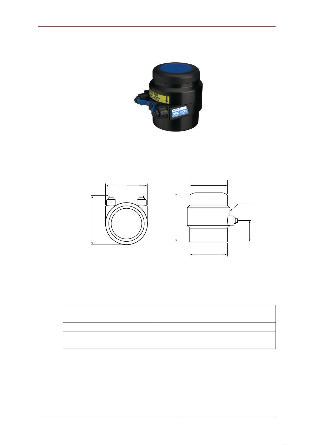
1.1. Dimensions
56
66
61
Ø50
Ø56
26
Not to scale, dimensions in mm.
Ø50
1.2. Physical
Weight in air 200g
Weight in water 60g
Depth rating 750m
Operating temperature -10 to 35°C
Storage temperature -20 to 50°C
Specification Micron Echosounder
0650-SOM-00001, Issue: 02 7 © Tritech International Ltd.
1.3. Acoustic Properties
Operating frequency 500kHz
Beamwidth 6° conical
Maximum range 50m
Minimum range 0.5m
Digital resolution 1mm
1.4. Electrical & Communication
Analogue output 0-5V DC on AUX port
Communication protocol RS485, RS232
Serial output format ASCII, NMEA
Topside control Computer with standard serial port
SeaHub or USB-RS232/RS485 converter
Power requirements 12-48V, 1.72W
1.5. Pin-out Diagram & Cable Specification
Caution
The Micron series connector is not wet mateable and direct exposure to water
when the unit is powered will cause damage.
Caution
Echosounders with part number S06377 should not be connected to the AUX port
of a Gemini 720im. The analogue voltage on the MAIN port of the Echosounder
will damage the Gemini 720im.

Specification Micron Echosounder
0650-SOM-00001, Issue: 02 8 © Tritech International Ltd.
S11975 Pinouts (Standard Echosounder after September 2018)
Main Port
Pin Wire Colour Function
1 Yellow RS485 A
RS232 TX
2 Blue RS485 B
RS232 RX
3 Red DC +
4 Black DC Ground
5 Green RS232 Ground
6 Cable Sheath Earth
Aux Port
Pin Wire Colour Function
1
2
3 Red DC +
4 Black Analogue Ground
DC Ground
5 Green Analogue output
6 Cable Sheath Earth
S06377 Pinouts (Standard Echosounder before September 2018)
Main Port
Pin Wire Colour Function
1 Yellow RS485 A
RS232 TX
2 Blue RS485 B
RS232 RX
3 Red DC +
4 Black DC Ground
RS232 Ground
Analogue Ground
5 Green Analogue Output
6 Cable Sheath Earth
Aux Port
Pin Wire Colour Function
1
2
3 Red DC +
4 Black Analogue Ground
DC Ground
5 Green Analogue output
6 Cable Sheath Earth

Micron Echosounder
0650-SOM-00001, Issue: 02 9 © Tritech International Ltd.
2. Introduction
The Micron Echosounder is a sonar ranging device which, when mounted vertically gives
the height above the seabed or in any other orientation will provide a method for measuring
subsea distances. The Echosounder can be configured to operate as a single device or
paired with other devices from the Micron range.
The altimeter data output from the Micron Echosounder can be transmitted as either an
analogue signal or using an RS232/RS485 protocol.
This manual covers the setup and use of the Micron Echosounder as a stand-alone unit.
There are a wide variety of different configurations available for the Micron Echosounder and
it is important to use this manual alongside the original purchase documentation to ensure
that the correct details are to hand.
Micron Echosounder
0650-SOM-00001, Issue: 02 10 © Tritech International Ltd.
3. Installation
3.1. Mounting
Optimal Orientation
Always mount the Micron Echosounder so that it is as close to the true vertical (or horizontal)
as possible in relation to the trim position of the vehicle.
Errors in the head alignment can give rise to unreliable results.
Mounting Material and Suitable Brackets
Caution
Avoid mounts that contain any metal alloys of copper such as brass or bronze.
Caution
Under no circumstances should the body tube be rotated within the clamp.
If torque is applied to the transducer or upper body tube they may unscrew
resulting in a unit that is no-longer water tight.
Non-metallic clamps should always be used where possible to prolong the life of the unit and
prevent any galvanic corrosion effects. If metallic clamps are used they should be electrically
insulated from the Echosounder body by means of rubber or plastic strips or mount brackets
of at least 3mm thickness and extending at least 3mm beyond the clamp boundary. It is
advised that metallic mounts should also be painted or lacquered with at least three coatings.
The Micron Echosounder can be mounted with a clamp around the body (the bottom half of
the Echosounder) or can be mounted using the holes on the base as detailed in Figure 3.1,
“Mounting Holes on Micron Range”.
Caution
Under no circumstance should a clamp be used on the transducer section (top
half) of the Micron.

Installation Micron Echosounder
0650-SOM-00001, Issue: 02 11 © Tritech International Ltd.
All dimensions are in millimetres.
Figure 3.1. Mounting Holes on Micron Range
3.2. Power
Caution
Unused connector sockets should be sealed against water ingress using the
provided blanking cap.
Caution
When mating the connectors ensure that both plug and socket are completely
dry.
The Micron Echosounder head is protected against voltage surges on the power and
communication lines using internal supressers. Sustained over voltage will damage the unit.
Power can be applied from a rectified transformer PSU and the output of the PSU must have
a filter capacitor of not less than 470μF, for each head being powered. If an unregulated PSU
is used, then make sure that the voltage value measured at the head is in the range specified
in Chapter 1, Specification, in power on/off and running conditions.
Note
To reduce the risk of damage due to over-voltage it is recommended that 100mA
fuses are used in the communication lines and appropriate fuse is used in the
power supply (e.g., 1A at 12V or 500mA at 24V).
Note
The Aux port provides pass through voltage from the Main port.
If using, or testing, with a SeaHub it is possible to power the Micron Echosounder from the
SeaHub using a combined power and data cable (port C or D). Please refer to the SeaHub
manual for details of the port pin-out diagram or contact Tritech International Ltd who can
provide a ready made cable.
If using an RS232 connection from a computer, or if the Echosounder is mounted to an ROV
it will be necessary to construct a cable with an appropriate Micron connector on one end and
power/data on the other end. Contact Tritech International Ltd for an appropriate cable whip.

Installation Micron Echosounder
0650-SOM-00001, Issue: 02 12 © Tritech International Ltd.
Caution
Never attempt to operate the Micron Echosounder at the end of a long cable by
increasing the PSU output voltage above the maximum rated voltage of the unit.
3.3. Communications
Caution
The power should be turned off before making a connection between the sonar
head and surface controller (SCU or SeaHub).
3.3.1. Port Layout
Note
For pin-out diagrams and cable specification refer to Chapter 1, Specification.
The Micron Echosounder is supplied with two communications ports labelled MAIN and AUX.
All serial communication to the control computer on the surface or to another micron device
should be via the MAIN port.
The AUX port of the micron sonar is used only for analogue voltage output. If only analogue
voltage is required then the MAIN port can be left blanked off and the power supplied via
the AUX port.
The communication configuration of the ports are factory set (although they can be changed
in software) . The factory setting is written on the label attached to the Micron, and can also
be obtained from the original build record.
Any combination of protocols RS232 and RS485 on the main and aux port are possible.
Note
If the settings are changed through software it is important to keep a record
of the changes, otherwise it can become very difficult to re-connect to the
Echosounder.
3.3.2. RS232 Characteristics
The RS232 telemetry is bi-directional, 3-wire (TX, RX and ground) with a maximum speed
of 115.2kbps.
This may form the connection between the Echosounder and the control computer RS232
COM port. Typically this is a DE-9 port or via a DE-9 to USB converter if the computer has no
native RS232 ports (such as in modern laptops). It is also possible to connect via an RS232
modem or multiplexer.
Maximum cable length
Depending on the type of conductors used, the RS232 may only drive up to 20m
of copper cable. For longer cable lengths it is necessary to run through a repeater
or converter, or switch to optical fibre with an RS232 telemetry option.

Installation Micron Echosounder
0650-SOM-00001, Issue: 02 13 © Tritech International Ltd.
It is possible to connect over a longer cable using a pair of RS232 to RS485 (or
RS422) converters and only using the RS232 connection over short ranges near
the Echosounder head and control computer.
3.3.3. RS485 Characteristics
The RS485 telemetry is half-duplex, 2-wire (RS485 A (or -) and RS485 B (or +)) with a
maximum speed of 115.2kbps.
The surface RS485 connection is typically through an RS485 serial COM port installed in the
computer (usually desktop computers) or an RS485 to RS232 signal converter. This protocol
is also used when connecting a Micron Echosounder to the AUX port of a Micron Sonar.
Note
The RS485 circuit inside the Micron has a factory supplied 150Ω termination
resistor fitted. A matching resistor may be fitted to the surface side if the twisted
pair length requires it.
Maximum cable length
The RS485 protocol is capable of a maximum of 2000m using high quality twisted
pair cable.
3.3.4. Analogue Characteristics
Pin 5 of the AUX connector on the Micron Echosounder is able to output an analogue signal
which relates to the depth measured by the Echosounder.
This output will be calibrated from 0.03 to 5V to represent 0.5 to 50m depth.

Micron Echosounder
0650-SOM-00001, Issue: 02 14 © Tritech International Ltd.
4. Operation
Note
The output from the Echosounder can be in serial or analogue format. This
section only covers applications which use the data in serial format.
4.1. Output Strings
The serial output is either interrogated (i.e., the software asks for a response) or free-running
and will continuously send out acoustic pulses and supply the output from the Echosounder
to the connected computer even if the software is not running.
The output is an ASCII data string terminated with a carriage return and line feed (<CR><LF>)
and will be in one of three formats depending on the hardware settings. These formats are
as follows:
3P2 xxx.xxm<CR><LF>
xxx.xx = range in metres to 2 decimal places
m = units label for metres
<CR><LF> = carriage return and line feed terminators.
3P3 xxx.xxxm<CR><LF>
xxx.xxx = range in metres to 3 decimal places
m = units label for metres
<CR><LF> = carriage return and line feed terminators.
NMEA
$DBT $PADBT,xxx.xx,f,yyy,yy,M,zzz.zz,F*hh<CR><LF>
xxx.xx is the range in feet
yyy.yy is the range in metres
zzz.zz is the range in fathoms
hh is an 8-bit checksum
<CR><LF> = carriage return and line feed terminators.
In free running mode the unit will start to output data immediately upon power up. If the
Echosounder has been set to interrogate mode it will not output data until the interrogate
command (Z) is received, at which point a single data string is transmitted to the surface
computer.
To confirm which mode the Echosounder is in a simple test is to power on the unit and listen
for any audible clicks or pings. In free running mode the Echosounder will start pinging as
soon as it receives power but in interrogated mode it should remain silent.

Operation Micron Echosounder
0650-SOM-00001, Issue: 02 15 © Tritech International Ltd.
Warning
NEVER place the transducer close to the ear to listen for the clicks. Doing so
could result in permanent damage to the eardrum. Always remain at least 15cm
away from the transducer.
4.2. Data Stream Characteristics
The default Echosounder output communication characteristics are as follows:
• 8 data bits
• 1 stop bit
• No parity
• No flow control
Depending on the hardware setup the unit will either output a 0 result or the maximum
possible result whenever a valid signal is not detected (i.e., fail low or fail high). These settings
are, respectively, Zero No Echo (ZNE) or Max No Echo (MNE).

Micron Echosounder
0650-SOM-00001, Issue: 02 16 © Tritech International Ltd.
5. Configuration
The Micron Echosounder is configured at the factory and it is not normally possible to re-
configure it in the field.
5.1. Connecting the Echosounder to other Micron products
Note
When daisy chained, the Micron Echosounder should be placed at the end of the
chain. In the example of a Micron Sonar and Responder setup, the Echosounder
should be placed on the AUX port of the Responder.
In this situation you will need to make sure that the AUX port of the responder is
set to a communication protocol and baud rate that matches your Echosounder.
Compatible products are the MicronNav Responder (AUX port), and MK2 or MK3 Micron
Sonar (AUX port). It is recommended that the Echosounder is set as below:
• RS485
• 3P2 string (xxx.xxm<CR><LF>) or 2P3 string (xx.xxxm<CR><LF>)
• Free running mode
• Zero No Return
• No analogue output (unless using a custom cable).
5.2. MAIN Port Communication Protocol
The MAIN port of the Micron Echosounder can be configured for either RS485 or RS232.
5.3. AUX Port Communication Protocol
The AUX port of the Micron Echosounder is for analogue output only.
5.4. Baud Rate
The baud rate can be configured to be one of the following:
• 115.2kbps
• 57.6kbps
• 38.4kbps
• 19.2kbps

Configuration Micron Echosounder
0650-SOM-00001, Issue: 02 17 © Tritech International Ltd.
• 9.6kbps
• 4.8kbps
• 2.4kbps
5.5. Serial Output String
The output string can be configured for one of three options:
• 3P2
• 3P3
• NMEA
For more details of the string format please refer to Chapter 4, Operation.
5.6. Other Options
The Echosounder can be set to be free-running or interrogated. In free running mode it will
output constantly as soon as power is applied, while in interrogated mode it will only output
when it is sent a 'Z' character from the surface control computer.
The "no return echo" can be set to either 0m or 50m. This means that if an echo comes back
which is beyond the acceptable range the Echosounder will return either a reading of 0m or
50m to the surface computer.

Micron Echosounder
0650-SOM-00001, Issue: 02 18 © Tritech International Ltd.
6. Maintenance
6.1. After each use of the equipment
Make sure that after using the Echosounder it is washed down with fresh water and check
the unit for any signs of obvious damage.
Once the unit is clean; dry thoroughly and place in the storage container.
Note
If the unit is fitted to an ROV it is advisable to remove from its fitting and wash both
with fresh water and dry both thoroughly prior to re-assembly. This will prevent
the build up of corrosive salts in any crevices between the sonar and mounting
bracket.
6.2. Regular maintenance
There are no user serviceable parts inside the Echosounder and should not be taken apart
for routine maintenance tasks.
It is recommended that a regular inspection routine be established. Particular attention should
be payed to the transducer and stress points, such as the connectors.
If the system is in regular use, or submerged routinely for extended periods, it is advisable to
arrange for an annual service to be carried out by Tritech International Ltd. This service will
enable the equipment to be checked thoroughly and any worn parts to be replaced enabling
long-term trouble free operation. For details of the servicing options available contact Tritech
International Ltd.
6.3. Storage of Equipment
If storing the equipment for extended periods make sure that it is completely dry (if necessary
leave to air-dry before stowing).
Pack into storage containers along with several pouches of silica gel. The original packing
containers contain specific foam cut-outs for the storage of the equipment and wherever
possible should be re-used. The foam will absorb moisture so if the cases are allowed to get
wet they should be dried thoroughly prior to stowing equipment in them.
Any supplied cabling is jacketed with polyurethane which is resistant to corrosion but if it is
intended to store the reel for an extended period without use then it is advisable to un-reel
the cable and dry its entire length. This will also give the opportunity to inspect the cable for
any damage which may have occurred during use.
Micron Echosounder
0650-SOM-00001, Issue: 02 19 © Tritech International Ltd.
Appendix A. CHIRP Signal Processing
There are several advantages of Tritech International Ltd Digital Sonar Technology (DST)
which allows the use of CHIRP signal processing technology to improve the images
generated by the sonar.
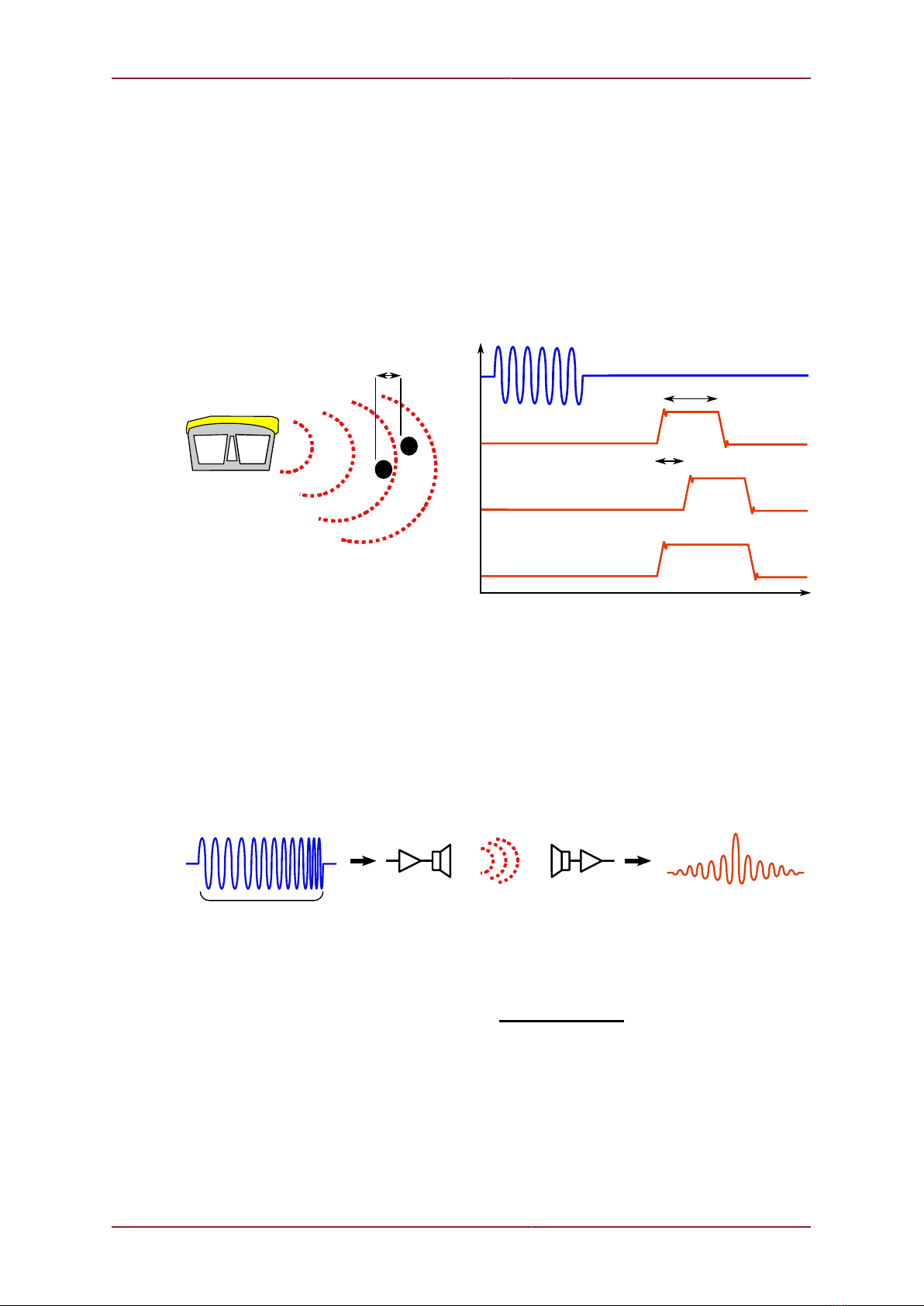
In monotonic (single frequency burst) sonar, the range resolution is determined by the length
of the transmitted pulse. The smaller the pulse, the greater the resolution achievable and
vice-versa. The smallest pulse length is typically 50 micro seconds and velocity of sound in
water is approximately 1500 metres/second which gives a range resolution of 37.5mm. This
result determines the ability to resolve separate targets.
T1
T2
Combined echo
(seen by the receiver)
Target 2 echo
Target 1 echo
Transmitted Pulse
Sonar range
resolution
Target
seperation
Time
Target
Seperation
Using the example above, if two targets are less than 37.5mm apart then they cannot be
distinguished from each other. The net effect is that the system displays a single large target,
rather than multiple smaller targets.
CHIRP signal processing overcomes these limitations by sweeping the frequency within the
burst over a broad range of frequencies throughout the duration of transmission pulse. This
creates a signature acoustic pulse - the sonar knows what was transmitted and when. Using
pattern matching technology, it can now look for its own unique signature being echoed back
from targets.
Transmitted signal
Transmitter
circuit
Receiver
circuit
Received decoded signal
pulse duration
In a CHIRP system, the critical factor determining range resolution is the bandwidth of the
CHIRP pulse which means the range resolution is given by:
Range resolution = velocity of sound
2 x bandwidth
The bandwidth of a typical Tritech International Ltd CHIRP system is 50kHz.
With velocity of sound in water of 1500m/s this gives a new range resolution of 15mm.
This time, when two acoustic echoes overlap, the signature CHIRP pulses do not merge into
a single return. The frequency at each point of the pulse is different, and the sonar is able
to resolve the two targets independently.

CHIRP Signal Processing Micron Echosounder
0650-SOM-00001, Issue: 02 20 © Tritech International Ltd.
T1
T2
Combined echo
Target 2 echo
Target 1 echo
Transmitted Pulse
Sonar range
resolution
Target
seperation
Time
Target
Seperation
Both targets
are visible.
The response from the pattern-matching algorithms in the sonar means that the length of
the acoustic pulse no longer affects the amplitude of the echo on the sonar display. Longer
transmissions (and operating ranges) can be achieved without a loss in range resolution.
CHIRP gives additional improvements in background noise rejection, as the sonar is only
looking for a swept frequency echo and can remove random noise or out-of-band noise.
Table of contents
Other Moog Marine Equipment manuals

Popular Marine Equipment manuals by other brands

Electro Detectors
Electro Detectors Zerio Plus EDA-R6030 installation instructions

Stinger
Stinger SPXM1 installation guide

Furuno
Furuno CSH-5 MARK-2 Operator's guide

New Age
New Age PRM Delta Workshop manual

Fike
Fike Twinflex Soundpoint 313-0021 Installation and maintenance instructions

Kongsberg
Kongsberg EM 2040C Maintenance manual


