E2S STExS1 User manual

INSTRUCTION MANUAL (ATEX / IECEx)
STExS1
Alarm Horn Sounder
For use in Flammable Gas and Dust Atmospheres
European Safety Systems Ltd. Impress House, Mansell Road, Acton, London W3 7QH
www.e2s.com
Tel: +44 (0)208 743 8880
Document No. D199-00-001-IS
Issue 5
01-11-21
Sheet 1 of 7
STExS1R
STExS1F
1) Product Table
Nominal
Input Voltage
Voltage Range
Nominal
Input Current
Max.
Current
Sound
Pressure Level
dB(A)
Max*
Nom.†
STExS1RDC024
12Vdc
11.5-54Vdc
221mA
221mA
110
105
24Vdc
185mA
48Vdc
115mA
STExS1RAC230
115Vac
110-240Vac 50/60Hz
73mA
80mA
110
105
230Vac
48mA
STExS1FDC024
12Vdc
11.5-54Vdc
221mA
221mA
115
110
24Vdc
185mA
48Vdc
115mA
STExS1FAC230
115Vac
110-240Vac 50/60Hz
73mA
80mA
115
110
230Vac
48mA
*Max = Tone 4
†Nom. = Tone 44
The table shows the input current taken by the various sounders.
Supply voltage variation of +/-10% outside the voltage range is permissible.
The current levels shown above are for the 440Hz Continuous tone @ nominal input voltage.
Nominal current at nominal voltage.
Max rated current at worst case supply voltage.
Table 1: Electrical Ratings.
Ensure the system power supply is capable of providing the maximum current required for all beacons. Review associated cable size,
length and quantity of beacons on each circuit.

European Safety Systems Ltd. Impress House, Mansell Road, Acton, London W3 7QH
www.e2s.com
Tel: +44 (0)208 743 8880
Document No. D199-00-001-IS
Issue 5
01-11-21
Sheet 2 of 7
2) Warnings
•DO NOT OPEN WHEN ENERGISED.
•DO NOT OPEN WHEN AN EXPLOSIVE ATMOSPHERE IS
PRESENT.
•POTENTIAL ELECTROSTATIC CHARGING HAZARD.
•ALL ENTRIES M20 X 1.5MM.
•IF TEMPERATURE EXCEEDS 70°C AT ENTRY OR 80°C
AT BRANCHING POINT USE SUITABLE RATED CABLE
AND CABLE GLANDS.
•IF OPENING THE UNIT DURING MAINTENANCE
OPERATIONS A CLEAN ENVIRONMENT MUST BE
MAINTAINED AND ANY DUST LAYER REMOVED PRIOR
TO OPENING THE UNIT.
3) Marking & Rating Information
All units have a rating label, which carries the following
important information.
Products may have further approvals, see E2S website for
further details.
ATEX / IECEx Ratings
Standards
EN IEC 60079-0:2018 / IEC60079-0:2017 (Ed 7):
Explosive Atmospheres - Equipment. General requirements
EN60079-1:2014 / IEC60079-1:2014 (Ed 7):
Explosive Atmospheres - Equipment protection by
flameproof enclosures "d"
EN 60079-31:2014 / IEC 60079-31:2013 (Ed 2):
Explosive Atmospheres - Equipment dust ignition protection
by enclosure "t"
Model No:
Rating
STExS1DC024
STExS1AC230
Ex db IIC T6 Gb Ta -50°C to +65°C
Ex db IIC T5 Gb Ta -50°C to +70°C
Ex db IIIC T82°C Db Ta -50°C to +70°C
Certificate No.
DEMKO 16 ATEX 1466X
IECEx ULD 16.0017X
Epsilon x
Equipment Group
and Category:
II 2G
II 2D
CE Marking and
Notified Body No.
2813
4) Zones, Gas Group, Category and
Temperature Classification
The units can be installed in locations with the following
conditions:
Area Classification
Zone 1
Explosive gas air mixture likely to occur in
normal operation.
Zone 2
Explosive gas air mixture not likely to occur in
normal operation, and if it does, it will only exist
for a short time.
Zone 21
Explosive dust air mixture likely to occur in
normal operation.
Zone 22
Explosive dust air mixture not likely to occur in
normal operation, and if it does, it will only exist
for a short time.
Gas Groupings
Group IIA
Propane
Group IIB
Ethylene
Group IIC
Hydrogen and Acetylene
Temperature Classification for Gas Applications
T1
450oC
T2
300oC
T3
200oC
T4
135oC
T5
100ºC
(STExS1 up to 70ºC ambient)
T6
85ºC
(STExS1 up to 65ºC ambient)
Dust Groupings
Group IIIA
Combustible Flyings
Group IIIB
Non-conductive Dust
Group IIIC
Conductive Dust
Maximum Surface Temperature for Dust Applications
STExS1
82ºC
Equipment Category
2G / 2D
Equipment Level Protection
Gb, Gc, Db, Dc
Ambient Temperature Range
-50°C to +70°C
IP Rating
IP6X to EN/IEC60079-0
IP66 to EN60529

European Safety Systems Ltd. Impress House, Mansell Road, Acton, London W3 7QH
www.e2s.com
Tel: +44 (0)208 743 8880
Document No. D199-00-001-IS
Issue 5
01-11-21
Sheet 3 of 7
5) Special Conditions for Safe Use
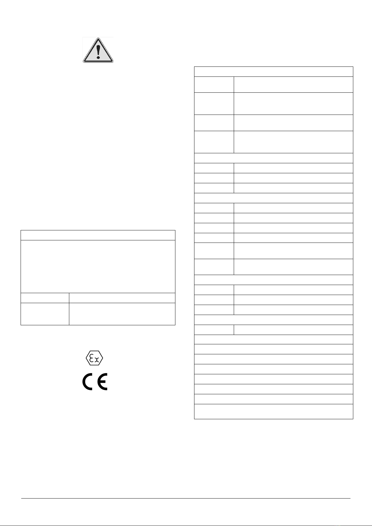
Repair of the Flame Path is not permitted.
Figure 1: Flame Path
The plastic horn is not anti-static, and the metallic enclosure
has a non-conductive coating. These may generate an
ignition-capable level of electrostatic charges under certain
extreme conditions. The user should ensure that the
equipment is not installed in a location where it may be
subjected to external conditions that might cause a build-up of
electrostatic charges on non-conducting surfaces.
6) Product Mounting and Access
6.1. Location and Mounting
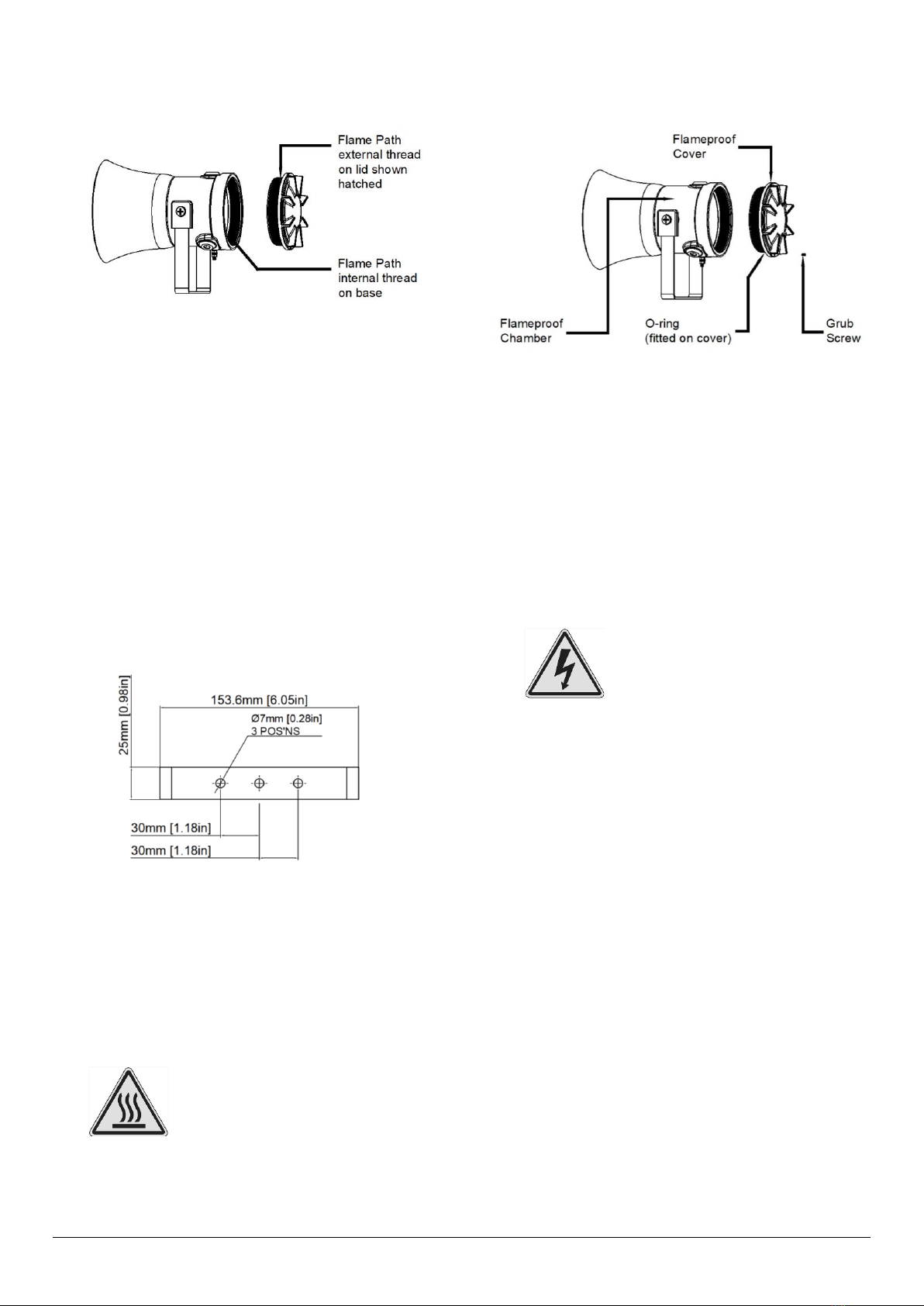
The sounder should be secured to any flat surface using the
three 7mm fixing holes (see figure 2). The angle can then be
adjusted as required but the mounting restrictions must be
observed (see outline drawings for details, D199-05-001 for
STExS1F and D199-05-021 for STExS1R). This can be
achieved by loosening the two large bracket screws in the side
of the unit, which allow adjustments in steps of 18°.
Figure 2: Fixing Location for STEx[S1R/S1F] Sounder.
On completion of the installation the two large bracket
adjustment screws on the side of the unit must be fully
tightened to ensure that the unit cannot move in service.
The enclosure provides IP66 protection and is suitable for
installation in exterior locations providing it is positioned so that
water cannot collect in the horn, and the cable entry is sealed.
6.2. Access to the Flameproof Enclosure
Warning –Hot surfaces. External
surfaces and internal components
may be hot after operation, take
care when handling the equipment.
In order to connect the electrical supply cables to the sounder
it is necessary to remove the flameproof cover to gain access
to the flameproof chamber. To access the Ex d chamber,
loosen the M4 grub screw on the sounder cover. Open the
enclosure by turning the sounder cover counterclockwise and
remove the cover, taking extreme care not to damage the
flameproof threads in the process (See figure 3).
Figure 3: Accessing the Explosion Proof Enclosure.
On completion of the installation, the flameproof threaded joint
should be inspected to ensure that they are clean and that they
have not been damaged during installation.
Ensure that the ‘O’ ring seal is in place and undamaged.
When fitting the flameproof cover ensure the thread is
engaged correctly. Fully tighten the cover all the way, ensure
no gap is visible between the cover and base of the sounder
enclosure. Tighten the M4 grub screw.
7) Installation Requirements
7.1. Installation Standards Compliance
Warning –High voltage may be
present, risk of electric shock.
DO NOT open when energised,
disconnect power before opening.
The sounder must only be installed by suitably qualified
personnel in accordance with the latest issues of the relevant
standards.
ATEX / IECEx installation standards:
EN60079-14 / IEC60079-14: Explosive atmospheres -
Electrical installations design, selection and erection.
EN60079-10-1 / IEC60079-10-1:Explosive atmospheres -
Classification of areas. Explosive gas atmospheres.
EN60079-10-2 / IEC60079-10-2:Explosive atmospheres -
Classification of areas. Explosive dust atmospheres.
The installation of the units must also be in accordance with
any local codes that may apply and should only be carried out
by a competent electrical engineer who has the necessary
training.
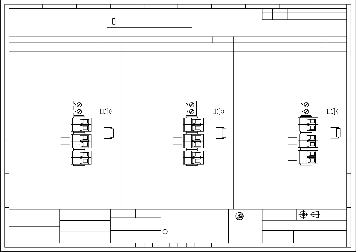
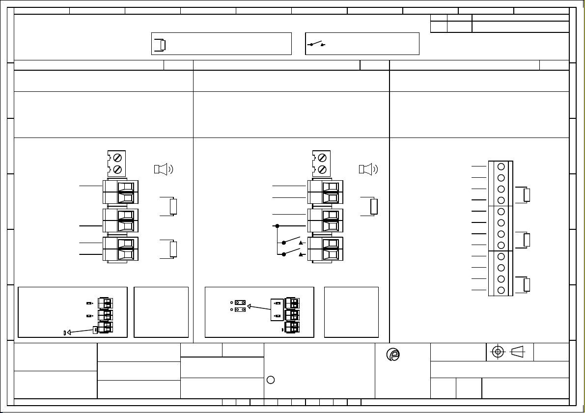
7.2. Cable Selection and Connections
When selecting the cable size, consideration must be given to
the input current that each unit draws (see table 1), the number
of sounders on the line and the length of the cable runs. The
cable size selected must have the necessary capacity to
provide the input current to all of the sounders connected to
the line.

European Safety Systems Ltd. Impress House, Mansell Road, Acton, London W3 7QH
www.e2s.com
Tel: +44 (0)208 743 8880
Document No. D199-00-001-IS
Issue 5
01-11-21
Sheet 4 of 7
Electrical connections are to be made into the terminal blocks
on the PCBA located in the flameproof enclosure using solid
wire 0.5-4mm² / AWG 20-12 or stranded wire, sizes 0.5-
2.5mm² / AWG 24-14. Wire insulation needs to be stripped
8mm. Wires may be fitted securely with crimped ferrules.
Figure 4: Wire Preparation.
Terminal screws need to be tightened down with a tightening
torque of 0.45 Nm / 5 Lb-in. An 8-way terminal block is
provided on the AC Sounder, and a 6-way terminal block is
provided on the DC Sounder.
Figure 5: STExS1 Entries and Terminal Block Location.
When connecting wires to the terminals great care should be
taken to dress the wires so that when the cover is inserted into
the chamber the wires do not exert excess pressure on the
terminal blocks. This is particularly important when using
cables with large cross-sectional areas such as 2.5mm².
Earthing
Both AC and DC sounder units must be connected to an earth
according to EN/IEC 60079/14. The units are provided with
internal and external earth terminals which are both located on
the terminal chamber section of the unit (see figure 5).
Internal earthing connections should be made to the PCB
terminal block or to the Internal Earth terminal in the base of
the housing using a ring crimp terminal to secure the earth
conductor under the earth clamp. The earth conductor should
be at least equal in size and rating to the incoming power
conductors.
External earthing connections should be made to the M5 earth
stud, using a ring crimp terminal to secure the earth conductor
to the earth stud between the two M5 stainless steel flat
washers, then reassemble the M5 spring washer and tighten
the M5 nut to ensure that the cable lug is secured against
loosening and twisting. The external earth conductor should be
at least 4mm2in size.
7.3. Cable Glands, Blanking Elements & Adapters
For high ambient temperatures the cable entry or the cable
branching point temperatures may exceed:
•70ºC at entry point.
•80ºC at branching point.
Therefore, suitable heat resisting cables and cable glands
must be used, with a rated service temperature at least as
stated in the table below:
Max Ambient Temperature (ºC)
Model
45
50
55
60
65
70
STExS1
70
75
80
85
90
95
Table 2: Min. Ratings of Cables & Cable Glands.
Cable Glands
Appropriate cable glands to be customer supplied.
The cable entries have an M20 x 1.5 –6H entry thread. Only
suitably rated and ATEX / IECEx certified cable glands must
be used. They must be suitable for the type of cable being
used and also meet the requirements of the current installation
standards EN 60079-14 / IEC60079-14.
Blanking Plugs
When only one cable entry is used the other entries must be
closed with suitably rated and certified blanking plugs as per
type of approval.
Any unused cable entries must be closed with suitably rated
and ATEX / IECEx certified blanking plugs.
Ingress Protection
If a high IP (Ingress Protection) rating is required, then a
suitable sealing washer must be fitted under the cable glands
or blanking plugs. A minimum ingress protection rating of IP6X
must be maintained for installations in explosive dust
atmospheres.
For combustible dust applications, the cable entry device and
blanking elements shall be in type of explosion protection and
shall have an IP 6X rating.
Adapters
The STEx sounder range can be supplied with the following
types of adapters:
M20 to ½” NPT
M20 to ¾” NPT
M20 to M25
It is important to note that stopping plugs cannot be fitted onto
adapters, only directly onto the M20 entries.
Any other adapters used must be suitably rated and ATEX /
IECEx certified adapters.
If the installation is made using conduit, openings must have a
sealing fitting connected as close as practical to the wall of the
enclosure, but in no case more than the size of the conduit or
50mm, whichever is the lesser.

European Safety Systems Ltd. Impress House, Mansell Road, Acton, London W3 7QH
www.e2s.com
Tel: +44 (0)208 743 8880
Document No. D199-00-001-IS
Issue 5
01-11-21
Sheet 5 of 7
8) Settings
Following illustrations show the different settings available for
STExS1 Alarm Horn Sounders. See schematic diagrams
D190-06-001 for DC units and D190-06-005 for AC units.
8.1. SPL Configuration
See Table 1 for product power supply and Sound Pressure
Levels (SPL).
Configuration for DC Units
Figure 6: DC PCBA SPL Configuration.
Configuration for AC Units
Figure 7: AC PCBA SPL Configuration.
8.2. Stage Switching Polarity (DC Units)
Switching from positive switching (default) to negative
switching - DC Only.
NOTE: Max supply is 33V DC –if higher DC voltage is
required, use Negative switching.
Figure 8: Stage Switching Polarity.
8.3. Tone Selection
The STExS Alarm Horn Sounders have 64 different tones that
can be selected independently for the first and second stage
alarms. The tones are selected by operation of the tone setting
DIP switch 1 & DIP 2witch 2 (see figures 6 and 7) on the PCB,
for stage 1 and stage 2 respectively.
Default = S2 –Tone 1
Default = S1 –Tone 44
(ON = 1, OFF = 0)
Figure 9: DIP switch configuration
The sounder can also be switched to sound the third and fourth
stage alarm tones.
The tone table (D221-95-001-IS) shows the switch positions
for the 64 tones on first and second stages and which tones
are available for the third and fourth stages dependent on the
Stage 1 DIP switch setting.
Following table (Table 3) is a summary of the wiring options.

European Safety Systems Ltd. Impress House, Mansell Road, Acton, London W3 7QH
www.e2s.com
Tel: +44 (0)208 743 8880
Document No. D199-00-001-IS
Issue 5
01-11-21
Sheet 6 of 7
Figure
Voltage
Configuration
Features
Default
Option
Special
Code
Identifier
See documents D190-06-001 for DC schematic diagrams.
1a
DC
Single Stage Configuration
•Line monitoring
•Positive Switching
Default
-
1b
DC
Two Stage Configuration
•Common Negative
•Positive Switching
Default
-
1c
DC
Three/Four Stage Configuration
•Common Negative
•Positive Switching
Default
-
2
DC
Three/Four Stages. Voltage Free 2nd, 3rd &
4th Stage Activation Configuration
•Common Positive
•Customer Set H1 & H2 to Negative
Switching
-
-
3
DC
Two Stage Configuration
•Independent Stage Input
•Reverse Polarity Stage Monitoring
-
-
4
DC
Two Stage Configuration
•Line Stage Monitoring (Use suitable
monitoring relays/ modules)
•Not to be used in reverse polarity
monitoring
Custom
Y
5
DC
Two/Three Stage Voltage Free Activation
Configuration
Custom
K
6
DC
Three/Four Stage Configuration
•Independent Stage Input
•Line Stage Monitoring (Use suitable
monitoring relays/ modules)
•Positive Switching (Default)
Custom
V
See documents D190-06-005 for AC schematic diagrams.
1a
AC
Single Stage Configuration
Default
-
1b
AC
Three/Four Stage Configuration
Default
-
2
AC
Two Stage Voltage Free Activation
Configuration
Custom
K
Table 3: Summary of Wiring Options. See documents D190-06-001 for DC and D190-06-005 for AC units schematic diagrams.
9) End of Line Monitoring (DC Units)
All DC units have a blocking diode fitted in their supply input
lines. An end of line monitoring diode or an end of line
monitoring resistor can be connected across the +ve and –ve
terminals in the flameproof chamber. See D190-06-001 for
details.
If an end of line resistor is used it must have a minimum
resistance value of 3k3 ohms and a minimum wattage of 0.5W
or a minimum resistance value of 500 ohms and a minimum
wattage of 2W.
The resistor must be connected directly across the +ve and -
ve terminals as shown in the following drawing. The resistor
leads should be kept as short as possible.
Figure 10: End of Line Resistor placement.
9.1. Custom DC Multi-Stage End Of Line Monitoring
An optional 12-way terminal module is available to enable up
to four alarm stages to be activated from three DC voltage
output channels. The three alarm stage activation inputs can
be independently monitored.
Refer to Schematic D190-06-001, Config. 6.
Specify Product option ‘V’ when ordering.
Spare part code for field installation: SP78-0001
Figure 11: End of Line Resistor placement –Optional 12-Way
Terminal Module.

European Safety Systems Ltd. Impress House, Mansell Road, Acton, London W3 7QH
www.e2s.com
Tel: +44 (0)208 743 8880
Document No. D199-00-001-IS
Issue 5
01-11-21
Sheet 7 of 7
10) Maintenance, Overhaul and Repair
Maintenance, repair and overhaul of the equipment should
only be carried out by suitably qualified personnel in
accordance with the current relevant standards:
EN60079-19/IEC60079-19
Explosive atmospheres –Equipment repair, overhaul and
reclamation
EN 60079-17/IEC60079-17
Explosive atmospheres –Electrical installations inspection
and maintenance
Flameproof threaded joints and cemented joints are not
permitted to be repaired.
Units must not be opened while an explosive atmosphere is
present.
If opening the unit during maintenance operations a clean
environment must be maintained and any dust layer removed
prior to opening the unit.
Potential electrostatic charging hazard - Clean only with a
damp cloth.

warning signals
2S
D1x
EUROPEAN SAFETY SYSTEMS LTD
IMPRESS HOUSE
MANSELL ROAD
ACTON
LONDON W3 7QH
WWW.E2S.COM
C
THIS DRAWING AND ANY INFORMATION OR DESCRIPTIVE
MATTER THEREIN IS COMMUNICATED IN CONFIDENCE AND
IS THE COPYRIGHT PROPERTY OF EUROPEAN SAFETY
SYSTEMS LTD. NEITHER THE WHOLE OR ANY EXTRACT MAY
BE DISCLOSED, LOANED, COPIED OR USED FOR
MANUFACTURING OR TENDERING PURPOSES WITHOUT THEIR
WRITTEN CONSENT.
EUROPEAN SAFETY SYSTEMS LTD.
AS PER LATEST DATE OF ISSUE SHOWN ABOVE
DRAWING TO BS8888:2000
GEOMETRIC TOLERANCES TO ISO1101:1983
LINEAR DIMENSIONAL TOLS
ANGULAR DIMENSIONAL TOLS
STANDARDS
MOD No. REASON - INITIAL - DATEISSUE
DATE
APPROVED
CHECKED DATE
DATE
DRAWN WEIGHT (Kg)
SURFACE FINISH
MATERIAL
ALTERNATIVE MATERIAL SHEETSCALE
TITLE
A3
IF IN DOUBT, ASK -
DO NOT SCALE
ALL DIMENSIONS IN MM
DRAWING NUMBER
A
B
C
D
E
F
G
109
G
F
E
78
6
5
D
C
134
2
A
B
D190-06-001
R.S.RAIT
B.ISARD
R.N.POTTS OF
NTS 1 3
OPTIONAL LINE MONITORING RESISTOR, CUSTOMER SUPPLIED,
14V MAX SYSTEM = 120Ω MIN, 2W MIN OR 1KΩ MIN, 0.5W MIN
28V MAX SYSTEM = 470Ω MIN, 2W MIN OR 2.4KΩ MIN, 0.5W MIN
RECOMMENDED MINIMUM VALUES:
R1
Stage 1 +ve IN
Stage 1 +ve OUT
Common -ve IN
Common -ve OUT
Stage 2 +ve
Stage 1 +ve IN
Stage 1 +ve OUT
Common -ve IN
Common -ve OUT
Stage 2 +ve
Stage 3 +ve
R1
+
-
-
+
R1
+
-
-
+
S2
R1
+
-
-
+
S2
S3
Stage 1 +ve IN
Stage 1 +ve OUT
Stage 1 -ve IN
Stage 1 -ve OUT
Single Stage Configuration Config.: 1a
Line Monitoring
Set to positive switching (default)
Stage 1: Apply Power to Stage 1 +ve & Stage 1 -ve
Two Stage Configuration Config.: 1b
Common Negative
Set to positive switching (default)
Stage 1: Apply Power to Stage 1 +ve & Common -ve
Stage 2: Apply Power to Stage 2 +ve & Common -ve
Three/Four Stage Configuration Config.: 1c
Common Negative
Set to positive switching (default)
Stage 1: Apply Power to Stage 1 +ve & Common -ve
Stage 2: Apply Power to Stage 2 +ve &Common -ve
Stage 3: Apply Power to Stage 3 +ve &Common -ve
Stage 4: Apply Power to Stage 2 +ve, Stage 3 +ve & Common -ve
19/01/2022
19/01/2022
19/01/2022
D1xS1 / D1xS2 / GNExS1 / GNExS2 / STExS1 /
STExS2 DC SOUNDER WIRING DIAGRAMS
INTRODUCTION
INTRODUCTION
1RSR - 19/01/2022

warning signals
2S
EUROPEAN SAFETY SYSTEMS LTD
IMPRESS HOUSE
MANSELL ROAD
ACTON
LONDON W3 7QH
WWW.E2S.COM
C
THIS DRAWING AND ANY INFORMATION OR DESCRIPTIVE
MATTER THEREIN IS COMMUNICATED IN CONFIDENCE AND
IS THE COPYRIGHT PROPERTY OF EUROPEAN SAFETY
SYSTEMS LTD. NEITHER THE WHOLE OR ANY EXTRACT MAY
BE DISCLOSED, LOANED, COPIED OR USED FOR
MANUFACTURING OR TENDERING PURPOSES WITHOUT THEIR
WRITTEN CONSENT.
EUROPEAN SAFETY SYSTEMS LTD.
AS PER LATEST DATE OF ISSUE SHOWN ABOVE
DRAWING TO BS8888:2000
GEOMETRIC TOLERANCES TO ISO1101:1983
LINEAR DIMENSIONAL TOLS
ANGULAR DIMENSIONAL TOLS
STANDARDS
MOD No. REASON - INITIAL - DATEISSUE
DATE
APPROVED
CHECKED DATE
DATE
DRAWN WEIGHT (Kg)
SURFACE FINISH
MATERIAL
ALTERNATIVE MATERIAL SHEETSCALE
TITLE
A3
IF IN DOUBT, ASK -
DO NOT SCALE
ALL DIMENSIONS IN MM
DRAWING NUMBER
A
B
C
D
E
F
G
109
G
F
E
78
6
5
D
C
134
2
A
B
D190-06-001
R.S.RAIT
B.ISARD
R.N.POTTS NTS
SWITCHES FOR STAGE OPERATION
CUSTOMER SUPPLIED
Stage 2 -ve
Common +ve IN
Common +ve OUT
Stage 1 -ve OUT
Stage 3 -ve
Stage 1 -ve IN
H2
H1
Stage 1 +ve
Stage 1 -ve
Stage 2 -ve
Stage 2 +ve
OF
2 3
R1
+
-
-
+
S2
S3
R1
+
-
-
+
S2
R2
OPTIONAL LINE MONITORING RESISTOR, CUSTOMER SUPPLIED,
14V MAX SYSTEM = 120Ω MIN, 2W MIN OR 1KΩ MIN, 0.5W MIN
28V MAX SYSTEM = 470Ω MIN, 2W MIN OR 2.4KΩ MIN, 0.5W MIN
RECOMMENDED MINIMUM VALUES:
R1
Set H1 & H2 to -ve switching
Three/Four Stages. Voltage Free 2nd, 3rd & 4th Stage Activation Configuration Config.: 2
Common Positive
Customer Set H1 & H2 to Negative Switching (See Below)
Stage 1: Apply Power to Common +ve & Stage 1 -ve
Stage 2: Apply Power to Common +ve & Stage 1 -ve & connect Stage 2 -ve to Stage 1 -ve
Stage 3: Apply Power to Common +ve & Stage 1 -ve & connect Stage 3 -ve to Stage 1 -ve
Stage 4: Apply Power to Common +ve & Stage 1 -ve
& connect Stage 2 -ve & Stage 3 -ve to Stage 1 -ve
Two Stage Configuration Config.: 3
Independent Stage Input
Reverse Polarity Stage Monitoring
Stage 1: Apply Power to Stage 1 +ve & Stage 1 -ve
Stage 2: Apply Power to Stage 1 +ve & Stage 1 -ve & connect Stage 2 -ve to Stage 1 -ve
H2
H1
Set H1 & H2 to -ve switching
Cut Link W1
INTRODUCTIONINTRODUCTION
1RSR - 19/01/2022
19/01/2022
19/01/2022
19/01/2022
D1x
D1xS1 / D1xS2 / GNExS1 / GNExS2 / STExS1 /
STExS2 DC SOUNDER WIRING DIAGRAMS

Stage 1 -ve
+ve IN
+ve OUT
-ve OUT
Stage 2 -ve
-ve IN/COMMON
warning signals
2S
EUROPEAN SAFETY SYSTEMS LTD
IMPRESS HOUSE
MANSELL ROAD
ACTON
LONDON W3 7QH
WWW.E2S.COM
C
THIS DRAWING AND ANY INFORMATION OR DESCRIPTIVE
MATTER THEREIN IS COMMUNICATED IN CONFIDENCE AND
IS THE COPYRIGHT PROPERTY OF EUROPEAN SAFETY
SYSTEMS LTD. NEITHER THE WHOLE OR ANY EXTRACT MAY
BE DISCLOSED, LOANED, COPIED OR USED FOR
MANUFACTURING OR TENDERING PURPOSES WITHOUT THEIR
WRITTEN CONSENT.
EUROPEAN SAFETY SYSTEMS LTD.
AS PER LATEST DATE OF ISSUE SHOWN ABOVE
DRAWING TO BS8888:2000
GEOMETRIC TOLERANCES TO ISO1101:1983
LINEAR DIMENSIONAL TOLS
ANGULAR DIMENSIONAL TOLS
STANDARDS
MOD No. REASON - INITIAL - DATEISSUE
DATE
APPROVED
CHECKED DATE
DATE
DRAWN WEIGHT (Kg)
SURFACE FINISH
MATERIAL
ALTERNATIVE MATERIAL SHEETSCALE
TITLE
A3
IF IN DOUBT, ASK -
DO NOT SCALE
ALL DIMENSIONS IN MM
DRAWING NUMBER
A
B
C
D
E
F
G
109
G
F
E
78
6
5
D
C
134
2
A
B
D190-06-001
R.S.RAIT
B.ISARD
R.N.POTTS NTS
Stage 1 +ve
Stage 1 -ve
Stage 2 +ve
Stage 2 -ve
OF
3 3
R1
+
-
-
+
R1
+
-
-
+
S2
R2
Two Stage Configuration Config.: 4
Line Stage Monitoring (Use suitable monitoring relays/modules)
Not to be used for reverse polarity monitoring
Stage 1: Apply Power to Stage 1 +ve & Stage 1 -ve
Stage 2: Apply Power to Stage 2 +ve & Stage 2 -ve
Two/Three Stage Voltage Free Activation Configuration Config.: 5
Customer Set H1 & H2 to Negative Switching (See Below)
Power: +ve & -ve
Stage 1: Connect Stage 1 -ve to Common -ve
Stage 2: Cconnect Stage 2 -ve to Common -ve
Stage 3: Connect both Stage 1 -ve & Stage 2 -ve to Common -ve
CUSTOM
CONFIGURATION
CONTACT E2S
WHEN ORDERING
Cut Link W1
H2
H1
Set H1 & H2 to -ve switching
CUSTOM
CONFIGURATION
CONTACT E2S
WHEN ORDERING
SWITCHES FOR STAGE OPERATION
CUSTOMER SUPPLIED
OPTIONAL LINE MONITORING RESISTOR, CUSTOMER SUPPLIED,
14V MAX SYSTEM = 120Ω MIN, 2W MIN OR 1KΩ MIN, 0.5W MIN
28V MAX SYSTEM = 470Ω MIN, 2W MIN OR 2.4KΩ MIN, 0.5W MIN
RECOMMENDED MINIMUM VALUES:
R1
Stage 1 +ve IN
Stage 1 +ve OUT
Three/Four Stage Configuration Config.: 6
Independent Stage Input
Line Stage Monitoring (use suitable monitoring relays/modules)
Set to positive switching (default)
Stage 1: Apply Power to Stage 1 +ve & Stage 1 -ve
Stage 2: Apply Power to Stage 2 +ve & Stage 2 -ve
Stage 3: Apply Power to Stage 3 +ve & Stage 3 -ve
Stage 4: Apply Power to Stage 2 +ve & Stage 2 -ve
& Apply Power to Stage 3 +ve & Stage 3 -ve
Stage 1 -ve IN
Stage 1 -ve OUT
Stage 2 +ve IN
Stage 2 +ve OUT
Stage 2 -ve IN
Stage 2 -ve OUT
Stage 3 +ve IN
Stage 3 +ve OUT
Stage 3 -ve IN
Stage 3 -ve OUT
R1R2R3
(CONFIGURATION SHOWS OPTIONAL
ADDITIONAL TERMINAL PCBA -
PRODUCT OPTION 'V')
19/01/2022
19/01/2022
19/01/2022
D1x
D1xS1 / D1xS2 / GNExS1 / GNExS2 / STExS1 /
STExS2 DC SOUNDER WIRING DIAGRAMS
INTRODUCTION
INTRODUCTION
1RSR - 19/01/2022

warning signals
2S
D1x
EUROPEAN SAFETY SYSTEMS LTD
IMPRESS HOUSE
MANSELL ROAD
ACTON
LONDON W3 7QH
WWW.E2S.COM
C
THIS DRAWING AND ANY INFORMATION OR DESCRIPTIVE
MATTER THEREIN IS COMMUNICATED IN CONFIDENCE AND
IS THE COPYRIGHT PROPERTY OF EUROPEAN SAFETY
SYSTEMS LTD. NEITHER THE WHOLE OR ANY EXTRACT MAY
BE DISCLOSED, LOANED, COPIED OR USED FOR
MANUFACTURING OR TENDERING PURPOSES WITHOUT THEIR
WRITTEN CONSENT.
EUROPEAN SAFETY SYSTEMS LTD.
AS PER LATEST DATE OF ISSUE SHOWN ABOVE
DRAWING TO BS8888:2000
GEOMETRIC TOLERANCES TO ISO1101:1983
LINEAR DIMENSIONAL TOLS
ANGULAR DIMENSIONAL TOLS
STANDARDS
MOD No. REASON - INITIAL - DATEISSUE
DATE
APPROVED
CHECKED DATE
DATE
DRAWN WEIGHT (Kg)
SURFACE FINISH
MATERIAL
ALTERNATIVE MATERIAL SHEETSCALE
TITLE
A3
IF IN DOUBT, ASK -
DO NOT SCALE
ALL DIMENSIONS IN MM
DRAWING NUMBER
A
B
C
D
E
F
G
109
G
F
E
78
6
5
D
C
134
2
A
B
D190-06-005
R.S.RAIT
B.ISARD
R.N.POTTS OF
NTS 1
SWITCHES FOR STAGE OPERATION
CUSTOMER SUPPLIED
1
Earth Earth
Stage 2
Stage 3
Common
Live IN
Live OUT
Neutral IN
Neutral OUT
Earth
Stage 1
Stage 2
Common
N
N
L
L
E
N
N
L
L
E
C
N
N
L
L
E
C
S2
S3
Live IN
Live OUT
Neutral IN
Neutral OUT
Stage 1 Live IN
Stage 1 Live OUT
Stage 1 Neutral IN
Stage 1 Neutral OUT
Single Stage Configuration Config.: 1a
Stage 1: Apply Power to Stage 1 Live & Stage 1 Neutral
Two Stage Voltage Free Activation Configuration Config.: 2
Power: Live & Neutral
Stage 1: Connect Stage 1 to Common
Stage 2: Connect Stage 2 to Common
Stage 3: Connect both Stage 1 & Stage 2 to Common
Three/Four Stage Configuration Config.: 1b
Stage 1: Apply Power to Live & Neutral
Stage 2: Apply Power to Live & Neutral
& connect Stage 2 to Common
Stage 3: Apply Power to Live & Neutral
& connect Stage 3 to Common
Stage 4: Apply Power to Live & Neutral
& connect both Stage 2 & Stage 3 to Common
CUSTOM
CONFIGURATION
CONTACT E2S
WHEN ORDERING
INTRODUCTION
1RSR - 19/01/2022
19/01/2022
19/01/2022
19/01/2022
D1xS1 / D1xS2 / GNExS1 / GNExS2 / STExS1 /
STExS2 AC SOUNDER WIRING DIAGRAMS

E2S Warning Signals Impress House, Mansell Road, Acton, London W3 7QH [email protected] e2s.com Page 1 of 1 D221-95-001-IS_Issue_A - 09/03/2021
1000Hz PFEER Toxic Gas
1200/500Hz @ 1Hz DIN /PFEER P.T.A.P.
1000Hz @ 0.5Hz(1s on, 1soff) PFEER Gen. Alarm
1.4KHz-1.6KHz 1s, 1.6KHz-1.4KHz 0.5s NF C 48-265
544Hz(100mS)/440Hz (400mS) NF S 32-001
1500/500Hz - (0.5s on , 0.5s off) x3 + 1s gap AS4428
500-1500Hz Sweeping 2 sec on 1 sec off AS4428
500/1200Hz @ 0.26Hz (3.3son, 0.5s off) Netherlands -
NEN 2575
1000Hz (1s on, 1s off)x7 + (7s on, 1s off) IMO Code 1a
420Hz(0.5s on, 0.5s off)x3 + 1s gap ISO 8201 Temporal
Pattern
1000Hz(0.5s on, 0.5s off)x3 + 1s gap ISO 8201 Temporal
Pattern
422/775Hz - (0.85 on, 0.5 off) x3 + 1s gap NFPA -
Temporal Coded
1000/2000Hz @ 1Hz Singapore
300Hz Continuous
440Hz Continuous
470Hz Continuous
500Hz Continuous IMO code 2 (Low)
554Hz Continuous
660Hz Continuous
800Hz IMO code 2 (High)
1200Hz Continuous
2000Hz Continuous
2400Hz Continuous
440Hz @0.83Hz (50
cycles/minute) Intermittent
470Hz @0.9Hz - 1.1s Intermittent
470Hz @5Hz - (5
cycles/second) Intermittent
544Hz @ 1.14Hz - 0.875s Intermittent
655Hz @ 0.875Hz Intermittent
660Hz @0.28Hz - 1.8sec
on, 1.8sec off Intermittent
660Hz @3.34Hz - 150mS
on, 150mS off Intermittent
745Hz @ 1Hz Intermittent
800Hz - 0.25sec on, 1 sec off Intermittent
800Hz @ 2Hz IMO code 3.a
(High) Intermittent
1000Hz @ 1Hz Intermittent
2400Hz @ 1Hz Intermittent
2900Hz @ 5Hz Intermittent
363/518Hz @ 1Hz Alternating
450/500Hz @ 2Hz Alternating
554/440Hz @ 1Hz Alternating
554/440Hz @ 0.625Hz Alternating
561/760Hz @0.83Hz (50
cycles/minute) Alternating
800/1000Hz @ 0.875Hz Alternating
2400/2900Hz @ 2Hz Alternating
500/1200Hz @ 0.3Hz Sweeping
560/1055Hz @ 0.18Hz Sweeping
560/1055Hz @ 3.3Hz Sweeping
660/1200Hz @ 1Hz Sweeping
800/1000Hz @ 1Hz Sweeping
800/1000Hz @ 7Hz Sweeping
800/1000Hz @ 50Hz Sweeping
2400/2900Hz @ 7Hz Sweeping
2400/2900Hz @ 1Hz Sweeping
2400/2900Hz @ 50Hz Sweeping
2500/3000Hz @ 2Hz Sweeping
2500/3000Hz @ 7.7Hz Sweeping
800Hz Motor Siren
1200Hz Motor Siren
2400Hz Motor Siren
Stage 1
Set DIP
SW 1
Tone No.
Tone Description Tone Visual
Stage 1 & 2
DIP SW 1/2
Settings
1 2 3 4 5 6
Stage 3
Set DIP
SW 1
(S3)
Stage 4
Set DIP
SW 1
(S2 + S3)
0 0 0 0 0 0
1
2
3
4
5
6
7
8
9
10
11
12
13
14
15
16
17
18
19
20
21
22
23
24
25
26
27
28
29
30
31
32
33
34
35
36
37
38
39
40
41
46
47
48
49
50
52
53
54
55
56
57
58
59
60
61
62
63
42
1 0 0 0 0 0
0 1 0 0 0 0
1 1 0 0 0 0
0 0 1 0 0 0
1 0 1 0 0 0
0 1 1 0 0 0
1 1 1 0 0 0
0 0 0 1 0 0
1 0 0 1 0 0
0 1 0 1 0 0
1 1 0 1 0 0
0 0 1 1 0 0
1 0 1 1 0 0
0 1 1 1 0 0
1 1 1 1 0 0
0 0 0 0 1 0
1 0 0 0 1 0
0 1 0 0 1 0
1 1 0 0 1 0
0 0 1 0 1 0
1 0 1 0 1 0
0 1 1 0 1 0
1 1 1 0 1 0
1 1 0 1 1 0
0 0 1 1 1 0
0 1 1 1 1 0
0 0 0 0 0 1
0 1 0 0 0 1
1 1 0 0 0 1
0 0 1 0 0 1
1 0 1 0 0 1
0 1 1 0 0 1
1 1 1 0 0 1
0 0 0 1 0 1
0 1 0 1 0 1
1 0 1 1 0 1
0 1 1 1 0 1
1 1 1 1 0 1
0 0 0 0 1 1
1 0 0 0 1 1
0 1 0 0 1 1
1 1 0 0 1 1
0 0 1 0 1 1
1 0 1 0 1 1
0 1 1 0 1 1
1 1 1 0 1 1
0 0 0 1 1 1
1 0 0 1 1 1
0 1 0 1 1 1
1 1 0 1 1 1
0 0 1 1 1 1
1 0 1 1 1 1
0 1 1 1 1 1
0 0 0 1 1 0
1 0 0 1 1 0
0 1 0 1 1 0
1 1 1 1 1 0
1 0 0 0 0 1
1 0 0 1 0 1
1 0 1 1 1 0
1000Hz
1200Hz
500Hz 1s
1000Hz 1s
1s
1600Hz
1400Hz 1s
0.5s
544Hz 0.1s
0.4s
440Hz
0.5s
1500Hz
500Hz 0.5s 0.5s 0.5s 0.5s 1s
2s 1s
3s 0.5s
1500Hz
500Hz
1200Hz
500Hz
1000Hz
1s
1s
1s
1s
1s
1s
1s
1s
1s
1s
1s
1s
1s
1s
7s
7s
420Hz 0.5s
0.5s
0.5s
0.5s
0.5s
1s
1000Hz 0.5s
0.5s
0.5s
0.5s
0.5s
1s
1200Hz
500Hz 0.85 0.5s 0.85 0.5s 0.85
2000Hz
1000Hz
1s
f(Hz)
a(s)
b(s)
(f=440, a=0.6, b=0.6)
(f=470, a=0.55, b=0.55)
(f=470, a=0.1, b=0.1)
(f=470, a=0.43, b=0.44)
(f=655, a=0.57, b=0.57)
(f=660, a=1.8, b=1.8)
(f=660, a=0.15, b=0.15)
(f=745, a=0.5, b=0.5)
(f=800, a=0.25, b=1)
(f=800, a=0.25, b=0.25)
(f=1000, a=0.5, b=0.5)
(f=2400, a=0.5, b=0.5)
(f=2900, a=0.1, b=0.1)
f1(Hz)
a(s)
f(Hz)
f1(Hz)
a(s) a(s)
f(Hz)
(f=363, f1=518, a=0.1)
(f=450, f1=500, a=0.25)
(f=440, f1=554, a=0.5)
(f=440, f1=554, a=0.8)
(f=561, f1=760, a=0.6)
0 0 1 1 0 1
1 1 0 1 0 1
43
44
45
780/600Hz @ 0.96Hz Alternating
800/1000Hz @ 2Hz Alternating
970/800Hz @ 2Hz Alternating
64
Simulated Bell
1 1 1 1 1 1
f1(Hz)
a(s) a(s)
f(Hz)
(f=800, f1=1000, a=0.57)
(f=2400, f1=2900, a=0.25)
f1(Hz)
a(s) a(s)
f(Hz)
(f=800, f1=1000, a=0.25)
f1(Hz) a(s) a(s)
f(Hz)
(f=600, f1=780, a=0.52)
f1(Hz) a(s) a(s)
f(Hz)
(f=800, f1=970, a=0.25)
(f=500, f1=1200, a=3.34)
(f=560, f1=1055, a=5.47)
(f=560, f1=1055, a=0.3)
f1(Hz)
a(s)
f(Hz)
51
600/1250Hz @ 0.125Hz Sweeping
(f=600, f1=1250, a=8)
f(Hz)
a(s)
(f=800, a=1.6)
(f=1200, a=2)
(f=2400, a=1.7)
1450Hz 0.25s
0.69ms
(f=660, f1=1200, a=1)
(f=800, f1=1000, a=1)
(f=800, f1=1000, a=0.14)
(f=800, f1=1000, a=0.02)
(f=2400, f1=2900, a=0.14)
(f=2400, f1=2900, a=1)
(f=2400, f1=2900, a=0.02)
(f=2500, f1=3000, a=0.5)
(f=2500, f1=3000, a=0.13)
(f=300)
(f=440)
(f=470)
(f=500)
(f=554)
(f=660)
(f=800)
(f=1200)
(f=2000)
(f=2400)
f(Hz)
0.5s
2
3
2
24
19
44
44
24
34
34
1
1
1
3
44
44
44
24
24
24
24
24
24
24
24
24
24
8
8
24
8
24
24
24
24
24
24
24
24
24
24
24
24
24
24
24
24
24
8
8
24
8
21
24
24
24
24
24
24
24
24
24
3
20
44
44
44
1
1
1
1
35
1
1
8
8
8
35
8
8
8
8
8
8
8
8
8
19
19
19
19
19
19
19
19
19
19
19
19
19
19
12
12
12
12
12
12
12
12
12
12
12
12
12
12
12
12
1
1
8
8
8
35
35
35
35
35
f1(Hz)
a(s)
f(Hz)

E2STelephone:+44(0)2087438880Fax:+44(0)2087404200Email:[email protected]www.e2s.comDC‐070_Issue_G(STEx).docx‐Page1of2‐QAF_252_Issue_5
EUDeclarationofConformity
Manufacturer: EuropeanSafetySystemsLtd.
ImpressHouse,MansellRoad,Acton
London,W37QH
UnitedKingdom
AuthorisedRepresentative:E2SWarnsignaltechnikUG
Charlottenstrasse45‐51
72764Reutlingen
Germany
EquipmentType: STExS1,STExS2,STExL1,STExL2
STExB2X05,STExB2X10,STExB2X15,STExB2X21
STExB2LD2,STExB2RT1
STExC1X05
STExJ2
Directive2014/34/EU:EquipmentandProtectiveSystemsforuseinPotentiallyExplosiveAtmospheres(ATEX)
NotifiedBodyforEUtypeExamination(ModuleB):ULInternationalDemkoA/S
NotifiedBodyNo.:0539
Borupvang5A,2750Ballerup,Denmark
EU‐typeExaminationCertificate(ModuleB):DEMKO16ATEX1466X
NotifiedBodyforQualityAssuranceNotification/ConformitytoEU‐type
basedon
qualityassuranceoftheproductionprocess(ModuleD):
SiraCertificationService
NotifiedBodyNo.:2813
CSAGroupNetherlandsB.V,Utrechtseweg310,6812AR,Arnhem,Netherlands
QualityAssuranceNotification(ModuleD):SIRA05ATEXM342
Provisionsfulfilledbytheequipment:II2GExdbIICT6…T3Gb
II2DExtbIIICT82°C…T137°CDb
IP6XDustProtectiontoEN60079‐0/EN60079‐31
Standardsapplied:ENIEC60079‐0:2018
EN60079‐1:2014
EN60079‐31:2014
Directive2014/30/EU:ElectromagneticCompatibilityDirective(EMC)
Standardsapplied:EN61000‐6‐1:2007
EN61000‐6‐2:2005
EN61000‐6‐3:2007/A1:2011/AC:2012
EN61000‐6‐4:2007/A1:2011
Directive2011/65/EU:Restrictionoftheuseofcertainhazardoussubstancesinelectricalandelectronicequipment(RoHS)
Theproductandallthecomponentscontainedwithinitareinaccordancewiththerestrictionoftheuseofhazardoussubstancesinelectricalandelectronic
equipment,includingamendmentbyDirective2015/863/EU.
Regulation(EC)1907/2006:Registration,Evaluation,AuthorisationandRestrictionofChemicals(REACH)
Theproductandallthecomponentscontainedwithinitarefreefromsubstancesofveryhighconcern.
OtherStandardsandRegulations
EN60529:1991/A1:2000/A2:2013‐Degreesofprotectionprovidedbyenclosures(IPcode)–enclosureratedIP66

E2STelephone:+44(0)2087438880Fax:+44(0)2087404200Email:[email protected]www.e2s.comDC‐070_Issue_G(STEx).docx‐Page2of2‐QAF_252_Issue_5
MartinStreetzDocumentNo.:DC‐070_Issue_G
QualityAssuranceManagerDateandPlaceofIssue:London,03/12/2021
EUDeclarationofConformity
OnbehalfofEuropeanSafetySystemsLtd.,Ideclarethat,onthedatetheequipmentaccompaniedbythisdeclarationisplacedonthemarket,theequipment
conformswithalltechnicalandregulatoryrequirementsoftheabovelisteddirectives,regulationsandstandards.
ThisDeclarationisissuedunderthesoleresponsibilityofthemanufacturer.
Other manuals for STExS1
2
This manual suits for next models
4
Table of contents
Other E2S Marine Equipment manuals

E2S
E2S BExA120D User manual

E2S
E2S STExS1 User manual

E2S
E2S DL112H User manual

E2S
E2S E2xS2FDC024 User manual

E2S
E2S MA1 Series User manual

E2S
E2S E2 S121UL Series User manual

E2S
E2S Minialarm IS-mA1 User manual

E2S
E2S AlertAlight AL121H User manual

E2S
E2S Sontel BExTS110DAC115 User manual

E2S
E2S STExS1 User manual