2
STAC6-Q-H Hardware manual
920-0109 Rev C
4/18/2023
Contents
Safety Instructions ..............................................................................................................................5
Over-Current Protection ...................................................................................................................7
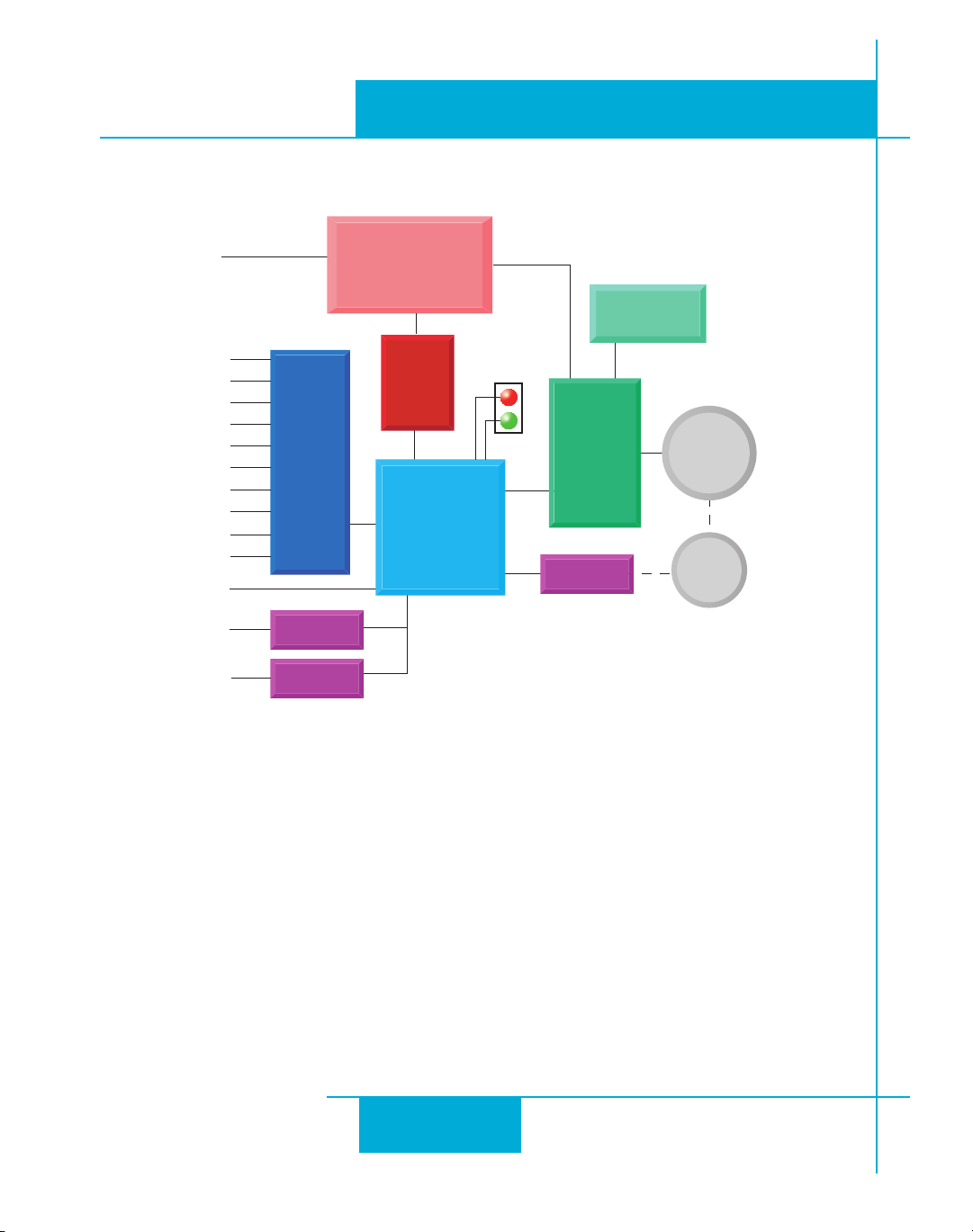
Block Diagram - STAC6-Q-H .................................................................................................................................................8
Motion Control Options....................................................................................................................9
STAC6-H Control Options......................................................................................................................................................9
Getting Started.................................................................................................................................. 10
Connecting to the PC using RS-232........................................................................................... 11
Connecting to the PC using RS-485........................................................................................... 12
Converting USB to RS-485 .................................................................................................................................................13
USB-COMi-M Switch Settings...........................................................................................................................................13
Assigning Addresses in Multi-axis Systems.................................................................................................................13
Connecting AC Power..................................................................................................................... 14
Fusing........................................................................................................................................................................................ 14
Line Filter.................................................................................................................................................................................. 14
Connecting the Motor.................................................................................................................... 15
Connecting an Encoder ................................................................................................................ 17
Encoder Feedback Options ............................................................................................................................................... 18
Wiring Inputs and Outputs ........................................................................................................... 19
Connecting Digital Inputs on the IN/OUT1 connector....................................................... 20
High Speed Digital Inputs.................................................................................................................................................. 20
Using High Speed Inputs with 12-24 Volt Signals..................................................................................................... 22
Standard Digital Inputs.......................................................................................................................................................23
Single Ended Inputs.............................................................................................................................................................23
What is COM? .........................................................................................................................................................................24
Digital Input Connection Examples ...............................................................................................................................24
Connecting Limit switches to the STAC6 Drive.......................................................................................................... 26
Wiring a Mechanical Limit Switch...................................................................................................................................26
Wiring a Limit Sensor........................................................................................................................................................... 27
Connecting Digital Outputs on the IN/OUT1 connector ................................................... 28
Connecting Analog Inputs on the IN/OUT1 connector...................................................... 30
Basic Specications: .............................................................................................................................................................31
Connecting an Analog Input to a Potentiometer or Joystick ............................................................................... 31
Dierential Inputs ................................................................................................................................................................32
Mounting the Drive ......................................................................................................................... 34
Schedule of Limitations:.....................................................................................................................................................34
Electrical Ratings:..................................................................................................................................................................35
Markings: .................................................................................................................................................................................35
Mechanical Outline.......................................................................................................................... 36