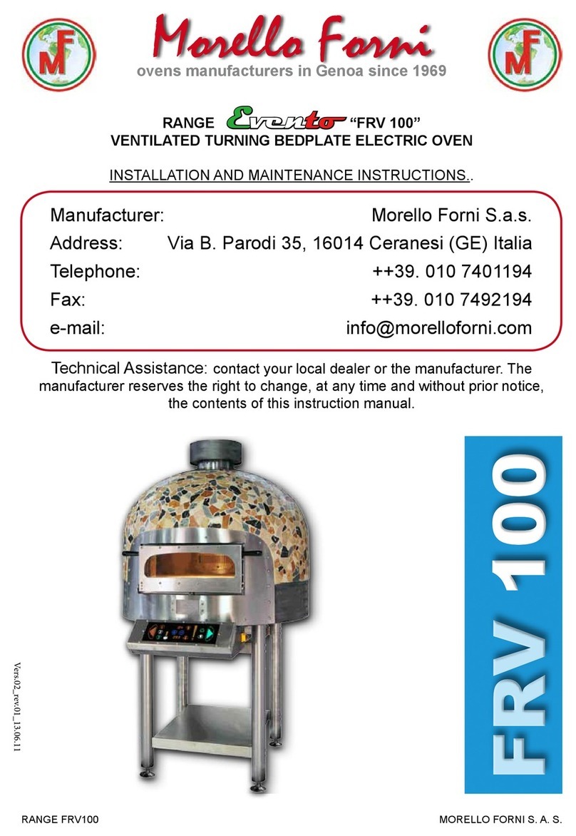
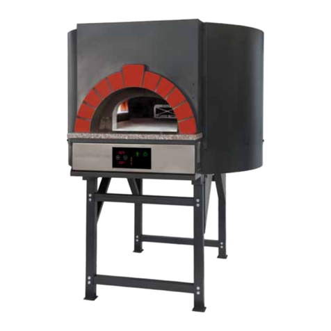
Morello Forni Evento FRV 100 User manual

FRV RANGE 1
rev.12 - 20102021
MORELLO FORNI ITALIA S.R.L.
ovens manufacturers in Genoa since 1969
RANGE Evento
“ FRV 100 ” “ FRV 125 ”
VENTILATED TURNING BEDPLATE ELECTRIC OVEN
INSTALLATION AND MAINTENANCE INSTRUCTIONS.
rev.12 - 21
Technical Assistance: contact your local dealer or the manufacturer.
The manufacturer reserves the right to change, at any time and without prior notice,
the contents of this instruction manual.
Manufacturer:
Address:
Telephone:
Fax:
e-mail:
Morello Forni Italia S.r.l.
Via B. Parodi 35, 16014 Ceranesi (GE) Italia
++39. 010 7401194
++39. 010 7492194
Morello Forni
FRV 100FRV 100
FRV 125FRV 125
FRV 100FRV 100
COLOSSEUM

FRV RANGE MORELLO FORNI ITALIA S.R.L.
2
rev.12 - 20102021
DICHIARAZIONE DECLARATION
DI CONFORMITA'
OF CONFORMITY
In accordo con : - la Direttiva Bassa Tensione Reg. 2014/35/UE,
-la Direttiva E.M.C. Reg. 2014/30/UE(Compatibilità Elettromagnetica),
-la Direttiva 2006/42 CE (macchine),
-il regolamento CE 1935/2004 (materiali ed oggetti destinati ad avvenire in contatto con prodotti alimentari).
According to the Low Voltage Directive 2014/35/EEC, the EMC Directive 2014/30/EEC, the Safety of
machinery 2006/42 EEC, with the rules CE 1935/2004 (materials and articles intended to come into contact
with foodstuffs)
Tipo di apparecchio - Type of equipment : Forno rotante elettrico ventilato - Rotary electric ventilated oven
Marchio commerciale -
Trademark : Morello Forni
Modello -
Type of designation : FRV
Costruttore -
Manufacturer : Morello Forni S.a.s. di Morello Marco & C.
Indirizzo -
Address : Via Bartolomeo Parodi 35 - 16014 Genova - ITALY
Telefono -
Telephone : (+39).010.7401194
Telefax -
Telefax : (+39).010.7492194
Le norme armonizzate o le specifiche tecniche (designazioni) che sono state applicate in accordo con le regole
della buona arte in materia di sicurezza in vigore nella CEE sono:
The following armonised standard or technical (designations) which comply with good engineering pratice in
safety matters in force within the EEC have been applied:
Norme o altri documenti normativi Rapporto collaudo - Schede tecniche
Standards or other normative documents Test report - Tecnical files
EN 60204.1 In fase di emissione - on progress
EN 60335.1, 60335.2.36
Emission: EN50081.1
Immunity: EN50082.1
Informazioni ulteriori
Additional informations
In qualità di costruttore e/o rappresentante autorizzato della società all'interno della CEE, si dichiara sotto la
propria responsabilità che gli apparecchi sono conformi alle esigenze essenziali previste dalle direttive su
menzionate.
As the Manufacturer's authorised representative established within EEC, we declare under out sole
responsability that the equipment follows the provision of the Directives state above.
Data e luogo di emissione
Nome e firma di persona autorizzata
Date and place of issue Name and signature of authorised person
................................................
..........................................................
(Capo Tecnico - Tecnical Director)

FRV RANGE 3
rev.12 - 20102021
MORELLO FORNI ITALIA S.R.L.
GENERAL INDEX
Declaration of Conformity . . . . . . . . . . . . . . . . . . . . . . . . . . . . . . . . . . . . . . . . . . . . . . . .
Chapter. 1 GENERAL CONTENTS . . . . . . . . . . . . . . . . . . . . . . . . . . . . . . . . . . . . . . . . . . .
1.1 Testing and warranty . . . . . . . . . . . . . . . . . . . . . . . . . . . . . . . . . . . . . . . . . . . . . . . . . . . . . . . . . . . . . . . . .
1.2 Premise . . . . . . . . . . . . . . . . . . . . . . . . . . . . . . . . . . . . . . . . . . . . . . . . . . . . . . . . . . . . . . . . . . . . . . . . . . .
1.3 Customer’s duties . . . . . . . . . . . . . . . . . . . . . . . . . . . . . . . . . . . . . . . . . . . . . . . . . . . . . . . . . . . . . . . . . . .
1.4 Oven description . . . . . . . . . . . . . . . . . . . . . . . . . . . . . . . . . . . . . . . . . . . . . . . . . . . . . . . . . . . . . . . . . . . .
1.5 Safety precautions . . . . . . . . . . . . . . . . . . . . . . . . . . . . . . . . . . . . . . . . . . . . . . . . . . . . . . . . . . . . . . . . . .
1.6 Contacting the technical assistance . . . . . . . . . . . . . . . . . . . . . . . . . . . . . . . . . . . . . . . . . . . . . . . . . . . . .
1.7 Ordering spare parts . . . . . . . . . . . . . . . . . . . . . . . . . . . . . . . . . . . . . . . . . . . . . . . . . . . . . . . . . . . . . . . . .
Chapter. 2 INSTRUCTIONS FOR INSTALLERS . . . . . . . . . . . . . . . . . . . . . . . . . . . . . . . . . . . . . . .
2.1 Weight and Dimensions . . . . . . . . . . . . . . . . . . . . . . . . . . . . . . . . . . . . . . . . . . . . . . . . . . . . . . . . . . . . . .
2.2 Receipt of the Oven . . . . . . . . . . . . . . . . . . . . . . . . . . . . . . . . . . . . . . . . . . . . . . . . . . . . . . . . . . . . . . . . .
2.3 General Recommendations . . . . . . . . . . . . . . . . . . . . . . . . . . . . . . . . . . . . . . . . . . . . . . . . . . . . . . . . . . .
2.4 Installing the oven . . . . . . . . . . . . . . . . . . . . . . . . . . . . . . . . . . . . . . . . . . . . . . . . . . . . . . . . . . . . . . . . . . .
2.5 Recommendations for external coating . . . . . . . . . . . . . . . . . . . . . . . . . . . . . . . . . . . . . . . . . . . . . . . . . .
Chapter. 3 INSTALLATION . . . . . . . . . . . . . . . . . . . . . . . . . . . . . . . . . . . . . . . . . . . . . . . . . . . . . . . . . . .
3.1 Electric connection and power absorption . . . . . . . . . . . . . . . . . . . . . . . . . . . . . . . . . . . . . . . . . . . . . . . .
3.2 Electrical Ratings ( * ) . . . . . . . . . . . . . . . . . . . . . . . . . . . . . . . . . . . . . . . . . . . . . . . . . . . . . . . . . . . . . . . .
3.3 Wiring Diagrams Information . . . . . . . . . . . . . . . . . . . . . . . . . . . . . . . . . . . . . . . . . . . . . . . . . . . . . . . . . .
3.4 List of Components ( FRV 100 ) . . . . . . . . . . . . . . . . . . . . . . . . . . . . . . . . . . . . . . . . . . . . . . . . . . . . . . . .
3.5 Exhaust Air Data ( * ) . . . . . . . . . . . . . . . . . . . . . . . . . . . . . . . . . . . . . . . . . . . . . . . . . . . . . . . . . . . . . . .
3.6 Discharge of the condensation produced . . . . . . . . . . . . . . . . . . . . . . . . . . . . . . . . . . . . . . . . . . . . . . . . .
- 3.6.1 FRV 100 . . . . . . . . . . . . . . . . . . . . . . . . . . . . . . . . . . . . . . . . . . . . . . . . . . . . . . . . . . . . . . . . . . . . . . .
- 3.6.2 FRV 125 . . . . . . . . . . . . . . . . . . . . . . . . . . . . . . . . . . . . . . . . . . . . . . . . . . . . . . . . . . . . . . . . . . . . . . .
Chapter. 4 PROGRAMMING AND CONTROL SYSTEM “Inteltouch - MF10”. . . . . . . . . . .
4.1 Oven start up . . . . . . . . . . . . . . . . . . . . . . . . . . . . . . . . . . . . . . . . . . . . . . . . . . . . . . . . . . . . . . . . . . . . .
4.2 Bedplate rotation controls description . . . . . . . . . . . . . . . . . . . . . . . . . . . . . . . . . . . . . . . . . . . . . . . . . .
4.3 Heaters commands description . . . . . . . . . . . . . . . . . . . . . . . . . . . . . . . . . . . . . . . . . . . . . . . . . . . . . . . .
4.4 Dome or bedplate temperature adjustment . . . . . . . . . . . . . . . . . . . . . . . . . . . . . . . . . . . . . . . . . . . .
4.5 Dome or bedplate heaters’ electric power adjustment . . . . . . . . . . . . . . . . . . . . . . . . . . . . . . . . . . . . .
4.6 Air Circulation inside the furnace adjustment . . . . . . . . . . . . . . . . . . . . . . . . . . . . . . . . . . . . . . . . . . . . .
4.7 Oven lamp . . . . . . . . . . . . . . . . . . . . . . . . . . . . . . . . . . . . . . . . . . . . . . . . . . . . . . . . . . . . . . . . . . . . . . . .
4.8 Cooking programs . . . . . . . . . . . . . . . . . . . . . . . . . . . . . . . . . . . . . . . . . . . . . . . . . . . . . . . . . . . . . . . . .
4.9 Programming example . . . . . . . . . . . . . . . . . . . . . . . . . . . . . . . . . . . . . . . . . . . . . . . . . . . . . . . . . . . . .
4.10 Cooking program use example . . . . . . . . . . . . . . . . . . . . . . . . . . . . . . . . . . . . . . . . . . . . . . . . . . . . . .
Appendix A. Maintenance tasks . . . . . . . . . . . . . . . . . . . . . . . . . . . . . . . . . . . . . . . . . . . .
Appendix B. Programmed startup instructions . . . . . . . . . . . . . . . . . . . . . . . . . . . . . .
Wiring Diagrams . . . . . . . . . . . . . . . . . . . . . . . . . . . . . . . . . . . . . . . . . . . . . . . . . . . . . . . .
FRV 100 Wiring diagram . . . . . . . . . . . . . . . . . . . . . . . . . . . . . . . . . . . . . . . . . . . . . . . . . . . . . . . . . . . . . . . .
FRV 125 Wiring diagram . . . . . . . . . . . . . . . . . . . . . . . . . . . . . . . . . . . . . . . . . . . . . . . . . . . . . . . . . . . . . . . .
2
4
4
4
4
5
5
5
5
6
6
7
8
8
9
10
10
10
10
11
11
12
12
13
14
14
15
16
17
18
19
19
20
20
21
22
28
29
29
30
(*) LEGAL DISCLAIMER :
MORELLO FORNI ITALY S.r.l. reserves the right to modify oven technical data and specs at any time, and without prior notice.
Said data and specications are purely indicative and in no way binding

FRV RANGE MORELLO FORNI ITALIA S.R.L.
4
rev.12 - 20102021
CHAPTER 1
GENERAL CONTENTS
1.1 TESTING AND WARRANTY
The unit has been tested in the manufacturer’s plant in compliance with current laws and regulations and is
supplied ready to use.
The warranty is valid 12 months from the date of delivery of the oven and covers the reparation of all
defective parts. Visible defects and dissimilarities in the order, if existing, must be reported to the manufac-
turer within 5 days from the date of receipt of the oven in order to be accepted.
All other defects that become evident after the receipt of the oven must be reported within ve days from
the date of occurrence or, at any rate, within a maximum of 6 months as stated in the warranty. The
purchaser shall be entitled to claim for the reparation or the replacement of the defective parts only, as the
warranty does not cover any whatsoever direct or indirect damage.
However, the reparation or replacement of defective parts must be requested within the maximum limit sta-
ted in the warranty, unless otherwise provided for in applicable laws and regulations.
Defective materials shall be repaired or replaced in the manufacturer’s plant. Therefore, the purchaser shall
return said materials carriage free to the manufacturer, who shall in turn return them carriage forward to the
customer.
1.2 PREMISE
This manual is supplied in order to provide all the instructions for a correct use and maintenance of the
oven, and the maximum safety of users.
The description of the following professional qualications and related duties are provided for further
clarication.
Installer: qualied technician in charge of the installation and commissioning of the oven in
accordance with the instructions of this manual.
User: any person who is familiar with the content of the manual and who uses the oven for the intended
use and in accordance with the instructions provided. Users are always expected to carefully read and
consult the manual. Users are recommended to specically and frequently read and refer to paragraph 1.5
Safety Precautions.
Technician responsible for ordinary maintenance: qualied technician trained to perform ordinary
maintenance operations in accordance with the instructions of this manual.
Technician responsible for extraordinary maintenance: qualied technician trained to perform
extraordinary maintenance on the unit.
The manufacturer disclaims all responsibility for damages originating from the improper and incorrect use of
the oven or from the failure to comply with the instructions of this manual.
This manual should be stored in an accessible location that is known to all users (installer and technicians
responsible for ordinary and extraordinary maintenance).
This manual cannot be reproduced and/or transmitted, in whole or in part, with any whatsoever means or
media.
1.3 CUSTOMER’S DUTIES
The customer shall be responsible for the following:
- Correct and safe installation of the oven received
- Power supply
- Connection to the ue
- Consumables for cleaning
- Ordinary maintenance
This symbol , which is present in some parts of this manual,
highlights an important warning that should be followed for safety purpose.

FRV RANGE 5
rev.12 - 20102021
MORELLO FORNI ITALIA S.R.L.
1.4 OVEN DESCRIPTION
An electric furnace, covered by a varnished metal shell that contains a refractory material heavy composite
structure; it is heated with a digitally controlled electrical resistances system (Fig.1).
The furnace front and its access door are made of metallic materials resistant to high temperatures; the
front control panel in stainless steel encloses the board with the digital control instrumentation.
1.5 SAFETY PRECAUTIONS
Before turning the oven on, it is always advisable to
read the instructions of this Operation and Mainte-
nance Manual, which is to be regarded as AN integral
part of the product and should always be stored in a
safe place. If this manual becomes unreadable or da-
maged, it is possible to request a duplicate copy from
the manufacturer by specifying the model and date of
supply of the oven.
GENERAL SAFETY PRINCIPLES:
• Always complete the recommended installation
procedure before turning the oven on.
• Avoid touching the oven with wet hands or feet.
• Avoid inserting screwdrivers or other objects in
the protection grilles of the oven or between mo-
ving parts.
• Do not disconnect the oven from the power sup-
ply by pulling the power cord out of the outlet.
• Do not allow children or youths below 18 or
unskilled people to use the oven.
• Always disconnect the oven from the power sup-
ply before cleaning or servicing it.
• Always turn the oven off without attempting any reparations in the event of permanent and/
or temporary failure.
• The oven should always be repaired by qualied technicians.
1.6 CONTACTING THE TECHNICAL ASSISTANCE
All technical problems or servicing requests should be addressed to the supplier of the oven.
1.7 ORDERING SPARE PARTS
All spare parts can be ordered from the supplier of the oven, who has a list of spare parts.
FIG.1

FRV RANGE MORELLO FORNI ITALIA S.R.L.
6
rev.12 - 20102021
CHAPTER 2.
INSTRUCTIONS FOR INSTALLERS
2.1 WEIGHT AND DIMENSIONS
The section below shows a layout of the unit, with its installation heights and dimensions in centimeters
(FIG.2, 3, 4) .
MORELLO FORNI ITALIA Srl
Via B. Parodi, 35 - 16014
Ceranesi (Genova) - Italy
Tel. +39 010 7401194
Fax + 39 010 7492194
info@morelloforni.com
www.morelloforni.com
i nostri ricambi / our spare parts
parts.morelloforni.com
LE IMMAGINI SONO PURAMENTE ILLUSTRATIVE E NON CONTRATTUALI • MISURE IN CM ± 2% • LE CARATTERISTICHE E I DATI RIPORTATI NEL PRESENTE CATALOGO POSSONO SUBIRE VARIAZIONI SENZA PREAVVISO
IMAGES ARE PURELY ILLUSTRATIVE AND NOT CONTRACTUAL • SIZES IN CENTIMETERS ± 2% • DATA AND FEATURES IN THIS CATALOG MAY CHANGE WITHOUT NOTICE
www.morelloforni.com
F
G
PQ
M
A
B
C
D
O
L
F
G
P Q
M
A
B
C
D
O
L
F
G
P Q
M
A
B
C
D
O
L
peso/weight (kg)
Mod./
Ref.
A B C DF G L M PO Q
FRV100 120 147 56 33 110 90 72 112 7056 70 650
FRV125 162 180 98 32 135 80 80 122 9065 110 1900
peso/weight (kg)
Mod./
Ref.
A B C DF G L M PO Q
FRV100 120 147 56 33 105 90 72 112 7056 70 650
FRV125 162 180 98 35 120 80 80 122 9065 110 1850
peso/weight (kg)
Mod./
Ref.
A B C DF G L M PO Q
FRV100 120 147 56 33 97 90 72 112 7056 70 650
FRV125 162 180 98 35 105 80 80 122 9065 110 1550
alcune nostre niture
some of our nishes
FRV 100 STANDARD FRV 125 CB NERO MORELLO FRV 100 CM-V CRYSTAL COPPER
FIG.2

FRV RANGE 7
rev.12 - 20102021
MORELLO FORNI ITALIA S.R.L.
The metal frame of the oven is designed to be handled with a transpallet.
The metal frame of the crane is designed to be handled with many types of
equipment.The special and reinforced HANDLING AND LIFTING POINT enables the
oven to be handled and lifted with a suitable transpallet trolley, as shown in FIG.8.
2.2 RECEIPT OF THE OVEN
Upon receipt of an oven manufactured by “MORELLO FORNI”, it is necessary to carefully read this manual
before performing any handling or installation operation.
The oven has been designed with the utmost attention and must be handled very carefully by the carrier.
All handling operations must be performed with efcient and appropriate unloading and installation
equipment. The oven is supplied with a disassembled support base due to the extremely high center of
gravity that could cause hazards and damage during transportation.
Extract the oven from its box by removing the supports and the rods of the elements that support the woo-
den crate anchored to the oven.
The oven should be handled only with equipment suitable to support its weight.
FOR THE SAFETY OF OPERATORS, IT IS ADVISABLE TO ALLOW THIS
OPERATION TO BE PERFORMED BY QUALIFIED TECHNICIANS ONLY.
ATTENTION! THE CENTER OF GRAVITY OF THE OVEN IS SITUATED HIGH
ABOVE THE GROUND.
LIFTING POINT
FIG.3
WARNING !
THE OVEN CANNOT
BE TILTED ON ANY
SIDE !

FRV RANGE MORELLO FORNI ITALIA S.R.L.
8
rev.12 - 20102021
2.3 GENERAL RECOMMENDATIONS
The oven can only be used to cook food. The sections below describe the main components of the
oven. The area below the oven must always be accessible and free from all possible obstructions..
THE MANUFACTURER DISCLAIMS ANY RESPONSIBILITY FOR DAMAGES ORIGINATING
FROM ACCIDENTS, FAULTS OR FROM THE FAILURE IN FOLLOWING THIS MANUAL’S INSTRUC-
TIONS .
Always perform all electric connections in accordance with safety law requirements and install a cut-off
switch to protect the oven from electric discharges and users from potential hazards.
Always make sure that the voltage and power supply are suited to the power absorbed by the oven.
2.4 INSTALLING THE OVEN
The furnace can be placed in any type of environment; we recommend that it be installed indoors.
The part underneath the motor and the control console must remain free of any type of obstruction and be
accessible for ordinary maintenance operations (FIG. 9), avoiding any form of occlusion that may prevent
the necessary air circulation, which is essential for the furnace to function properly.
AREA TO BE LEFT FREE
FIG.4
AREA TO BE LEFT FREE

FRV RANGE 9
rev.12 - 20102021
MORELLO FORNI ITALIA S.R.L.
2.5 RECOMMENDATIONS FOR EXTERNAL COATING
The oven can be coated with several materials, except for the front control panel and other areas
that must be left free, as shown in the layout below (Fig.10).
Always follow the recommended instructions and do not hesitate to contact the manufacturer for
further information.
Non combustible materials
like natural stones, ceramic
tiles, heat resistant or
ame-proof materials can
be applied directly on the
surface.
Heat sensitive or partially
combustible materials must be
applied by leaving a minimum
distance of at least 10 centimeters.
10 cm
FIG.5
PLEASE RESPECT FOLLOWING INSTALLATION DISTANCES
TO AVOID ANY DAMAGE TO OVEN’S EXTERNAL FINISH
AND INTERNAL COMPONENTS

FRV RANGE MORELLO FORNI ITALIA S.R.L.
10
rev.12 - 20102021
CHAPTER. 3
INSTALLATION
3.1 ELECTRIC CONNECTIONS AND POWER ABSORPTION
The oven must be connected to the power mains by a qualied
and authorized technician.
FRV 100 model must be connected to the mains through a 380 V,
three-phased ve-pole 3L+1N+PE, 32 Amperes, 50 Hz;
FRV125 model must be connected to the mains through a 380 V,
three-phased ve-pole 3L+1N+PE, 63 Amperes, 50 Hz.
To enhance safety, always observe the following instructions:
- Always use the power cord supplied with the oven for its
connection to the power supply.
- Verify that the power supply has the same rating of the oven.
- If outlet and plug are incompatible, replace the outlet with a suitable and approved model.
- Never use adapters or multiple plugs.
3.2 ELECTRIC RATINGS ( * )
TABLE 1 ELECTRICAL OVEN RATINGS
FRV RANGE
MODEL FRV 100 FRV 125
Maximum
Power
Consumption 15 kW 24 kW
Temperature
Mantaining
Average Power
Consumpion
2.5 kW 5 kW
3.3 WIRING DIAGRAMS INFORMATION
The wiring diagrams for FRV 100 and FRV 125 ovens are shown on the last two pages of this manual.
IMPORTANT
always connect the oven to an elec-
tric network system with a suitable
grounding system and cutoff switch
compliant with current safety law re-
quirements.
WIRING DIAGRAMS ARE DESIGNED TO BE USED BY QUALIFIED
TECHNICIANS DURING MAINTENANCE OPERATIONS.

FRV RANGE 11
rev.12 - 20102021
MORELLO FORNI ITALIA S.R.L.
3.4 COMPONENTS
1. Shunt trip release . . . . . . . . . . . .MF.03.008
2. Manual motor protector switch . . . . . . .MF.03.007
3. Voltage monitoring . . . . . . . . . . . .MF.03.006
4. Three Phase Solid State Relays Bedplate . . .MF.03.055
5. Three Phase Solid State Relays Dome . . . . MF.03.053
6. Electrical resistance Bedplate . . . . . . . .MF.03.021
7. Electrical resistance Bedplate . . . . . . . MF.03.021
8. Electrical resistance Bedplate . . . . . . . MF.03.021
9. Electrical resistance Bedplate . . . . . . . MF.03.021
10. Electrical resistance Bedplate . . . . . . . MF.03.021
11. Electrical resistance Bedplate . . . . . . . MF.03.021
12. Electrical resistance Dome ( kit of 6 pieces) . MF.03.010
13. Transformer 24V dc . . . . . . . . . . . MF.01.002 / 02.080
14. Inteltouch MF-R . . . . . . . . . . . . .MF.01.007
15. Engine for gear reductor . . . . . . . . . MF.03.002
16. Independent cooling fan . . . . . . . . . MF.03.002.02
17. Inverter . . . . . . . . . . . . . . . .MF.02.027
18. PLC . . . . . . . . . . . . . . . . . MF.01.003
19. Dome temperature probe . . . . . . . . . MF.03.061
20. Bedplate temperature probe . . . . . . . . MF.01.004
21. Door switch . . . . . . . . . . . . . . .MF.03.022
22. Light bulb . . . . . . . . . . . . . . .MF.03.035
23. Light bulb holder . . . . . . . . . . . . MF.03.036
24. Motor fan inverter . . . . . . . . . . . .MF.03.048
25. Motor fan . . . . . . . . . . . . . . .MF.03.020
26. Motor fan capacitor . . . . . . . . . . .MF.03.020.01
27. Electronics’ shelf cooling Fan . . . . . . . MF.03.019
28. Fuse 0,8 A . . . . . . . . . . . . . . MF.11.051
29. Fuse 1 A . . . . . . . . . . . . . . . MF.11.052
30. Fuse 1,6 A . . . . . . . . . . . . . . MF.11.052
31. Fuse 6,3 A . . . . . . . . . . . . . . . MF.11.055
32. Fuse 2,5 A . . . . . . . . . . . . . . .MF.11.053
3.5 TECHNICAL AIR EXTRACTION RATINGS ( * )
TABLE 2 EXHAUST VOLUME
FRV RANGE
MODEL FRV 100 FRV 125
Air Volume 600 m3 h 700 m3 h

FRV RANGE MORELLO FORNI ITALIA S.R.L.
12
rev.12 - 20102021
(*) Installer must guarantee, in any case, the correct and total extraction of steam produced during baking.
3.6 DISCHARGE OF BAKING STEAM PRODUCTS
3.6.1 - FRV 100
The furnace is equipped with a manifold to discharge steam that might be produced during baking (A in
Fig.11) which can be connected to a chimney. Manifolds B and C are respectively air inlet and outlet to cool
the motorfan assembly. Make sure that the manifolds B and C are always free of any obstruction, to ensure
the necessary air circulation, essential for the furnace to function properly.
WARNING!!
THE MOTOR AIR MANIFOLDS (B and C in Fig.11) MUST NOT BE CONNECTED
TO ANY TYPE OF CHIMNEY, THEY MUST REMAIN FREE!
WARNING!!
NEVER PLACE THE FRV OVEN UNDER A HOOD,
TO ALLOW PROPER COOLING OF ITS MOTORFAN
B
C
FIG.6
A

FRV RANGE 13
rev.12 - 20102021
MORELLO FORNI ITALIA S.R.L.
WARNING !!
THE INTAKE MOTOR FAN SQUARE FILTER REQUIRES CLEANING AT REGULAR IN-
TERVALS, ACCORDING TO MAINTENANCE SCHEDULE. TO PULL OUT THE FILTER,
OPEN THE TWO HINGES (SHOWN ABOVE), THEN RAISE ITS FRAME.
IF YOU ARE USING LIQUID DETERGENT TO CLEAN THE FILTER,
DRY IT COMPLETELY, BEFORE ASSEMBLING IT BACK AT ITS PLACE.
3.6.2 - FRV 125
e FRV 125 STANDARD “ COLOSSEUM”, above, has a single manifold to discharge steam that might be
produced during baking - its diameter is 10 cm. e installer must guarantee an average exhaust volume of
1000 m3/h.
It is possible to place the oven under a hood.
FIG.13
A
FIG.8
FIG.7

FRV RANGE MORELLO FORNI ITALIA S.R.L.
14
rev.12 - 20102021
CHAPTER 4
PROGRAMMING AND CONTROL SYSTEM “INTELTOUCH-MF10”
Control panel “Inteltouch MF10” is an advanced digital board control that enables the User to launch and
monitor oven main function.
“Inteltouch MF10” system, by acoustic warning, changes in icon light, colors, numeric signs, can
display oven status and programs.
User can activate or change functions by easy and direct One-touch, by following instruction listed below.
4.1 OVEN START UP
Once plugged, control panel shows stand-by mode:
One touch on icon (6) “ON-OFF” activates touch keyboard, as well as dome and bedplate temperature sen-
sor and relating status for thermostatic control readiness system.
Start button changes its Color from red to green to show activated status ( and viceversa when shutting
down ).
6
76543
8 9 10 11 12 13 14 15
21
(1) Bedplate clockwise rotation command. (9) Bedplate rotation speed command
(2) Cooking program # 2 command (10) Increase value command
(3) Cooking program # 1 command (11) Bedplate temperature indicator
(4) Dome temperature indicator (12) Decrease value command
(5) Dome burner command (13) Bedplate burner command
(6) ON-OFF Switch (14) Internal Ventilation adjustment command
(7) Bedplate counterclockwise rotation command (15) Light On-Off switch
(8) Cooking program # 3 command

FRV RANGE 15
rev.12 - 20102021
MORELLO FORNI ITALIA S.R.L.
NOTE: PID - Automatic electric power management system
The FRV range of electric ovens comes equipped with a heating power management software, to limit electric con-
sumption as much as possible, and improve performances consequently.
4.2 ROTATING BEDPLATE COMMANDS.
ROTATION DIRECTION SELECT
Both buttons (1) Red arrow button and (7) Green Arrow button change the bedplate’s rotation direction.
Touching once on red ( or green ) arrow starts rotation in the same direction of the arrow - arrow icon will
blink to conrm rotation is on.
Touching once on opposite arrow changes rotation direction - without stopping the rotation.
Touching again on the blinking arrow stops the bedplate from rotating.
9
(+) (-)
ROTATION SPEED
Rotation speed can be set, when bedplate is rotating and (1) Red arrow button or (7) Green Arrow are blin-
king, by touching once the (9) Bedplate rotation speed control icon, and after it starts blinking following
a beep sound, you can increase speed by touching (10) Value increase button , and decrease speed by
touching (12) Value decrease button.Yellow marks above the rotation icon (9) will light up, following the
increase or decrease of the rotation speed, from minimum to maximum.
After 5 seconds without any further touch, selected speed becomes set, and icon (9) stops blinking.

FRV RANGE MORELLO FORNI ITALIA S.R.L.
16
rev.12 - 20102021
4.3 HEATERS COMMANDS DESCRIPTION
It is possible to activate independently dome and / or bedplate electrical heaters by means of their specic
“enable and switch on/off” icons (5) and (13). Pressing once icon (5) “Dome heater icon” or (13) ”Bedplate
heater icon”, will select heater to be enabled and switched on. Actual heater start-and-stop is managed by
oven’s own Thermostatic System:
Green Icon - selected heater is enabled.
Red Icon - selected heater is disabled.
Depending on dome or bedplate set temperatures, each heater - when enabled by oven’s operator - will
automatically start and stop to mantain selected temperature value.
A Yellow led marker is located in the middle of each heater’s command icon; it lights up to indicate need for
thermostatic Intervention - i.e. when dome or bedplate need to be heated to reach set temperature - and
will switch off when set temperature is reached.
NOTE : Dome or Bedplate Heaters are functioning ONLY AND IF their Yellow Led is lit AND heater icon IS
green (enabled).
Here are a few panel sample images, to better explain thermostatic management logic:
let’s suppose Dome temperature is set to 130 °C; and Bedplate temp is set on 160° C
• Dome Heater: Enabled
• Dome Heater led: on
• Dome Heater status: ON
--------------------------------------
• Bedplate Heater: Disabled
• Bedplate Heater led: off
• Bedplate Heater status: OFF
• Dome Heater: Disabled
• Dome Heater led: on
• Dome Heater status: OFF
--------------------------------------
• Bedplate Heater: Disabled
• Bedplate Heater led: on
• Bedplate Heater status: OFF
• Dome Heater: Enabled
• Dome Heater led: on
• Dome Heater status: ON
--------------------------------------
• Bedplate Heater: Disabled
• Bedplate Heater led: off
• Bedplate Heater status: OFF

FRV RANGE 17
rev.12 - 20102021
MORELLO FORNI ITALIA S.R.L.
4.4 DOME OR BEDPLATE TEMPERATURE ADJUSTMENT
It is possible to adjust the baking temperature of the dome and / or the bedplate, by touching once on the
corresponding dome (4) or bedplate (11) Temperature Indicator; the same indicator will blink, and beep
once, to conrm that you have entered the Temperature changing mode. Press the Increase (10) or Decre-
ase (12) keys until the desired temperature is reached.
After 5 seconds from last touch, the Temperature Indicator will stop blinking, showing a steady temperature
indication, storing the last temperature set (no longer visible on the indicator, as now it is showing the tem-
perature at this moment).
EXAMPLE :
Let’s suppose that user wants to increase the temperature of the dome from 103 ° C to 118 ° C:
4
1. Touch the dome temperature
indicator once; the touch screen
interface conrms the command
with a single “BEEP” >>
2. The dome temperature indicator
ashes - it’s now possible to adjust
the dome temperature (in the
example, from 103 ° C to 118 ° C);
3. With the dome temperature
indicator blinking, touch the “+”
button repeatedly to increase the
temperature;
2. Once the desired dome tempe-
rature is reached, stop touching.
After 5 seconds from the last
touch, the temperature indicator
will stop blinking, storing the new
baking temperature.

FRV RANGE MORELLO FORNI ITALIA S.R.L.
18
rev.12 - 20102021
4.5 DOME OR BEDPLATE ELECTRIC POWER ADJUSTMENT
It is also possible to adjust the electrical power, independently, used by dome or bedplate heating elements,
while in the dome (4) or bedplate (11) temperature modication mode.
To enter the power modication mode:
- Touch the dome (or bedplate) temperature indicator two times, when the temperature is not blinking;
- (If temperature is blinking), touch the temperature indicator only once, while it’s blinking.
The Power modication mode entry is conrmed with a single “BEEP”, and the blinking “POT” indication,
in place of the dome Temperature indication; It is now possible to adjust the power, to the corresponding
dome ( or bedplate ) elements, in percentage from 0%, to 100%.
After 5 seconds from the last touch, the “POT” Indicator will return to normal mode (current temperature
indication), storing the last percentage power value set.
EXAMPLE:
Let’s suppose the user wants to adjust the power percentage of the dome elements from 80% to 90%:
1. The dome temperature shows
103 °C steady.
Touch the temp.indicator TWICE;
the touch interface conrms the
commands with two “BEEP”s, one
for each touch of the temperature
indicator.
2.A blinking “POT” message ap-
pears, indicating the power modi-
cation mode is on. The bedplate
temperature indicator reads “080”,
that is 80% of electrical power.
3. It’s now possible to adjust the
DOME electric power percentage (
from 80% to 90%, for example );
While “POT” indicator blinks, touch
repeatedly the “+” key to increase
the % power setting of the dome
elements;
2. Once the desired power percen-
tage is displayed, stop touching.
After 5 seconds from the last
touch, the “POT” indicator stops
blinking and shows Temperature
digits, storing the new power per-
centage.

FRV RANGE 19
rev.12 - 20102021
MORELLO FORNI ITALIA S.R.L.
4.6 AIR CIRCULATION INSIDE THE FURNACE ADJUSTMENT
Air circulation inside the furnace is managed by a modulating control system, and can be adjusted con-
tinuously from a minimum to a maximum level with one touch on the Internal Ventilation adjustment (14)
icon, conrmed by its blinking that indicates setting mode has been entered;
Then, by pressing the “+” (10) and “-” (12) keys, fan speed can be increased or decreased as preferred.
Air Ventilation level is indicated by an orange colored series of marks on a scale, increasing with every
touch of icon (10) from minimum (icon #14 top image) to maximum ( icon #14 bottom image).
After 5 seconds from last touch command, Scale and icon stop blinking, Air Circulation parameter is stored,
and ventilation is mantained.
4.7 OVEN LAMP
Ovens’ furnace Lighting System (optional) is controlled via Light On-Off switch (15) icon.
One touch on it will switch on the light, and icon color will change from blue to white.
12 1410
1410
15

FRV RANGE MORELLO FORNI ITALIA S.R.L.
20
rev.12 - 20102021
4.8 COOKING PROGRAMS
Rotating bedplate equipped ovens have proven being an excellent choice, amongst professionals, to shor-
ten baking time, and production consequently.
Thanks to oven’s own characteristics, the higher the bedplate rotation speed, the better the food-oven
thermal exchange and the more homogeneous temperatures will be, resulting in quicker and more uniform
baking. Therefore, it is better to bake at higher bedplate speeds than those used for product batching-in
and churning-out.
To reduce oven user workload, three Cooking program Fast Selection icons have been inserted on the
touch panel, identied by icons “1”,“2” and “3” ( in panel description image, respectively #3, #2 and #8 ).
Each icon recalls a different working program, customized on user needs and based on 3 parameters:
4.9 PROGRAMMING EXAMPLE.
Let’s suppose we want to program our FRV using storing position “1”.
Our program parameters shall be:
- Average baking time for a medium topped pizza : 3 mins.
- Batch in time : about 30 sec.
- Churn out time : about 30 sec.
- Time Gap between above operations : about 2 mins.
- Program End Warning Beeps : 5
To Store above parameters in Program #1 ( icon “1” ):
- Press more than 5 sec. icon “1”, entering programming mode,
.
Icon will start blinking, while Dome temperature indicator (4) changes to “U-1”.
User has entered bedpla te speed programming step. Bedplate temperature indicator (11) shows set
speed value, ranging from 0 to 20, which user can modify by pressing “+” (10) or “-” (12) icons
( let’s suppose a set value of 20 for this example’s sake).
PLEASE NOTE:
EVERY COOKING PROGRAM CAN BE STOPPED AND CANCELED
AT ANY TIME BY PRESSING SAME PROGRAM RECALL ICON
Other manuals for Evento FRV 100
1
This manual suits for next models
1
Table of contents
Other Morello Forni Oven manuals
Popular Oven manuals by other brands

Brandt
Brandt FC 222 user manual

aumate
aumate TOA20M04N-1E instruction manual

Maytag
Maytag CWE4100AC - 24" Single Electric Wall Oven Dimension Guide

Kernau
Kernau KBO 1076 S PT B instruction manual

Bosch
Bosch HB 37 N Series User manual and installation instructions

Electrolux
Electrolux EOD5420AA user manual