Morello Forni RANGE FGRi User manual

RANGE FGRi MORELLO FORNI S. A. S.
1
ovens manufacturers in Genoa since 1969
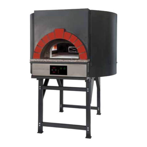
RANGE “FGRi” ROTARY GAS OVEN WITH DUAL BURNER
AND INDEPENDENT DIGITAL THERMOSTATIC CONTROLS
BETWEEN THE CROWN AND THE COOKING TOP
INSTALLATION AND MAINTENANCE INSTRUCTIONS.
Technical Assistance: contact your local dealer or the manufacturer.
The manufacturer reserves the right to change, at any time and without
prior notice, the contents of this instruction manual.
Manufacturer:
Address:
Telephone:
Fax:
e-mail:
Morello Forni S.a.s.
Via B. Parodi 35, 16014 Ceranesi (GE) Italy
++39. 010 7401194
++39. 010 7492194
Morello Forni
FGRiFGRi
FGRiUSA_200412_001

RANGE FGRi MORELLO FORNI S. A. S.
2
GENERAL INDEX
Chapter.1 General warnings . . . . . . . . . . . . . . . . . . . . . . . . . . . . . . . . . . . . . . . . . . . . . . . . . . . . . . . . . . . . . .
1.1 Testing and warranty
1.2 Introduction
1.3 Client’s responsibilities
1.4 Oven description
1.5 General safety standards
1.6 Contacting the technical assistance
1.7 Ordering spare parts
Chapter. 2 Instructions for the installers . . . . . . . . . . . . . . . . . . . . . . . . . . . . . . . . . . . . . . . . . . . . . . . . . . . .
2.1 Weight and dimensions
2.2 Receiving the oven
2.3 General recommendations
2.4 Installing the oven
2.5 Recommendations for external coating
Chapter. 3 Installation . . . . . . . . . . . . . . . . . . . . . . . . . . . . . . . . . . . . . . . . . . . . . . . . . . . . . . . . . . . . . . . . . . .
3.1 Electric connections and power absorption
3.2 Wiring diagram
3.3 List of componets
3.4 Discharge of combustion products
3.5 Technical data
3.6 Preparation of the oven
3.7 Operating characteristics
3.8 Adapting the oven for another types of gas
3.9 Connecting the gas supply
3.10 Technical features
3.11 Checking the supply pressure
3.12 Checking gas leaks
Chapter. 4 Control system of the oven . . . . . . . . . . . . . . . . . . . . . . . . . . . . . . . . . . . . . . . . . . . . . . . . . . . . . .
4.1 Safety device
4.2 Operating instructions
4.3 Moduplus: adjustment, operating test and maintenance
Chapter. 5 Instructions for users. . . . . . . . . . . . . . . . . . . . . . . . . . . . . . . . . . . . . . . . . . . . . . . . . . . . . . . . . . .
5.1 Oven operating instructions
5.2 Safety and control system for the oven gas
5.3 Thermal and oven pre-heating system
5.4 Switching the burners on and off
5.5 Lighting the wood furnace
5.6 Cleaning the oven
5.7 Note on the types of wood
Chapter. 6 Oven programming and control system “Inteltouch - MF10”. . . . . . . . . . . . . . . . . . . . . . . . . .
6.1 Oven Start up
6.2 Burners commands description
6.3 Temperature selection
6.4 Dome burner ame tuning
6.5 Oven lamp
6.6 Working programme
6.7 Setting a programme example
Wiring Diagram . . . . . . . . . . . . . . . . . . . . . . . . . . . . . . . . . . . . . . . . . . . . . . . . . . . . . . . . . . . . . . . . . . . . . . . . .
Pag. 3
Pag. 3
Pag. 3
Pag. 3
Pag. 4
Pag. 4
Pag. 4
Pag. 4
Pag. 5
Pag. 5
Pag. 6
Pag. 7
Pag. 7
Pag. 8
Pag. 9
Pag. 9
Pag. 9
Pag. 9
Pag. 10
Pag. 11
Pag. 11
Pag. 11
Pag. 11
Pag. 12
Pag. 12
Pag. 12
Pag. 12
Pag. 13
Pag. 13
Pag. 14
Pag. 15
Pag. 16
Pag. 16
Pag. 16
Pag. 17
Pag. 17
Pag. 18
Pag. 19
Pag. 19
Pag. 20
Pag. 20
Pag. 22
Pag. 22
Pag. 23
Pag. 23
Pag. 24
Pag. 25
Pag. 26

RANGE FGRi MORELLO FORNI S. A. S.
3
Chapter. 1 GENERAL WARNINGS
1.1 TESTING AND WARRANTY
The unit has been tested in the manufacturer’s plant in compliance with current laws and regulations and is
supplied ready to use.
The warranty is valid 12 months from the date of delivery of the oven and covers the reparation of all
defective parts, with the only exception of electric and electronic components. Visible defects and
dissimilarities in the order, if existing, must be reported to the manufacturer within 5 days from the date of
receipt of the oven in order to be accepted.
All other defects that become evident after the receipt of the oven must be reported within ve days from
the date of occurrence or, at any rate, within a maximum of 6 months as stated in the warranty.
The purchaser shall be entitled to claim for the reparation or the replacement of the defective parts only, as
the warranty does not cover any whatsoever direct or indirect damage.
However, the reparation or replacement of defective parts must be requested within the maximum limit
stated in the warranty, unless otherwise provided for in applicable laws and regulations.
Defective materials shall be repaired or replaced in the manufacturer’s plant. Therefore, the purchaser shall
return said materials carriage free to the manufacturer, who shall in turn return them carriage forward to the
customer.
1.2 INTRODUCTION
This manual is supplied in order to provide all the instructions for a correct use and maintenance of the
oven, and the maximum safety of users.
The description of the following professional qualications and related duties are provided for further
clarication.
Installer: qualied technician in charge of the installation and commissioning of the oven in accordance
with the instructions of this manual.
User: any person who is familiar with the content of the manual and who uses the oven for the intended
use and in accordance with the instructions provided. Users are always expected to carefully read and
consult the manual. Users are recommended to specically and frequently read and refer to paragraph 1.5
Safety Precautions.
Technician responsible for ordinary maintenance: qualied technician trained to perform ordinary
maintenance operations in accordance with the instructions of this manual.
Technician responsible for extraordinary maintenance: qualied technician trained to perform
extraordinary maintenance on the unit.
The manufacturer disclaims all responsibility for damages originating from the improper and
incorrect use of the oven or from the failure to comply with the instructions of this manual.
This manual should be stored in an accessible location that is known to all users (installer and
technicians responsible for ordinary and extraordinary maintenance).
This manual cannot be reproduced and/or transmitted, in whole or in part, with any whatsoever
means or media.
1.3 CLIENT’S RESPONSIBILITIES
The customer shall be responsible for the following:
- Correct and safe installation of the oven received
- Power supply
- Compliance of the gas supply with the testing requirements
- Connection to the ue
- Consumables for cleaning
- Ordinary maintenance
- manutenzione ordinaria
The symbol , which is present in some parts of this manual, highlights an
important warning that should be followed for safety purposes.

RANGE FGRi MORELLO FORNI S. A. S.
4
1.4 OVEN DESCRIPTION
This gas oven has an external body in painted sheet that houses a heavy composite frame in
refractory material and is heated by two digitally controlled gas burners (FIG.1).
The front arc and the shelf are in refractory granite and natural stone. The front control panel in
stainless steel houses the instrumentation panel and the digital controls.
1.5 GENERAL SAFETY STANDARDS
Before turning the oven on, it is always
advisable to read the instructions of this
Operation and Maintenance Manual, which is to
be regarded as an integral part of the product
and should always be stored in a safe place. If
this manual becomes unreadable or damaged,
it is possible to request a duplicate copy from
the manufacturer by specifying the model and
date of supply of the oven.
GENERAL SAFETY PRINCIPLES
- Always complete the recommended
installation procedure before turning the oven
on.
- Avoid touching the oven with wet hands or
feet.
- Avoid inserting screwdrivers or other objects
in the protection grilles of the oven or between
moving parts.
- Do not disconnect the oven from the power
supply by pulling the power cord out of the
outlet.
- Do not allow children or youths below 18 or
unskilled people to use the oven.
- Always disconnect the oven from the power
supply before cleaning or servicing it.
- Always turn the oven off without attempting
any reparations in the event of permanent
and/or temporary failure. The oven should
always be repaired by qualied technicians.
1.6 CONTACTING THE TECHNICAL ASSISTANCE
All technical problems or servicing requests should be addressed to the supplier of the oven.
1.7 ORDERING SPARE PARTS
All spare parts can be ordered from the supplier of the oven who has a list of spare parts.
FIG.1

RANGE FGRi MORELLO FORNI S. A. S.
5
Chapter. 2 Instructions for installers
2.1 WEIGHT AND DIMENSIONS
The section below shows a layout of the unit with the installation heights
and dimensions in centimeters (FIG.2).
Ref. /
Mod Ø A Ø B C D E F G I Ø M N P Q S T
FGRi 100 106 165 165 100 37 107 87 94 25 55 98 118 25 50
FGRi 110 126 185 187 110 37 107 87 104 30 65 118 118 25 50
FGRi 130 146 205 210 120 37 107 87 114 30 75 138 118 25 50
ALL DIMENSIONS ARE IN CENTIMETERS
Ref. /Mod Weight
(Kg)
FGRi 100 1700
FGRi 110 2200
FGRi 130 2600
FIG.2

RANGE FGRi MORELLO FORNI S. A. S.
6
2.2 RECEIVING OF THE OVEN
Upon receipt of an oven manufactured by “MORELLO FORNI”, it is necessary to carefully read this manual
before performing any handling or installation operation.
The oven has been designed with the utmost attention and must be handled very carefully by the carrier. All
handling operations must be performed with efcient and appropriate unloading and installation equipment.
The oven is supplied with a disassembled support base due to the extremely high center of gravity that
could cause hazards and damages during transportation.
Extract the oven from its box by removing the supports and the rods of the elements that support the woo-
den crate anchored to the oven.
The oven should be handled only with equipment suitable to support its weight.
FOR THE SAFETY OF OPERATORS, IT IS ADVISABLE TO ALLOW THIS
OPERATION TO BE PERFORMED BY QUALIFIED TECHNICIANS ONLY.
ATTENTION! THE CENTER OF GRAVITY OF THE OVEN IS SITUATED HIGH
ABOVE THE GROUND.
The metal frame of the oven is designed to be handled with a crane. The two metal bars
that form the upper frame can be used to x the lifting slings with a hoist or crane of
adequate carrying capacity.
The metal frame of the crane is designed to be handled with many types of equipment.
The special and reinforced HANDLING AND LIFTING POINT enables the oven to be
handled and lifted with a suitable transpallet trolley or with a hoist equipped with lifting
forks, as shown in FIG.3.
THE OVEN SHOULD NEVER BE ROTATED ON ITS SIDE!
FIG.3

RANGE FGRi MORELLO FORNI S. A. S.
7
2.3 GENERAL RECOMMENDATIONS
The oven can only be used to cook food. The sections below describe the main components of the oven.
The area below the oven must always be accessible and free from all possible obstructions.THE MANU-
FACTURER DISCLAIMS ANY RESPONSIBILITY FOR DAMAGES ORIGINATING FROM ACCIDENTS,
FAULTS OR FROM THE FAILURE TO FOLLOW THE INSTRUCTIONS OF THIS MANUAL.Always
perform all electric connections in accordance with safety law requirements and install a cut-off switch
to protect the oven from electric discharges and users from potential hazards.Always make sure that the
voltage and power supply are suited to the power absorbed by the oven.
2.4 INSTALLING THE OVEN
This oven, which is a combustion model, must be installed in a ventilated area in accordance with the
regulations of competent authorities.
It is useful to remember that the gas burners can be serviced only from the base of the oven, by remo-
ving the grilles that protect the openings next to the location of the internal burner.As maintenance tech-
nicians need to regularly use these openings to access the gas burners and service them, it is important
to make sure that they are always accessible and free from obstructions that could prevent the correct
circulation of the air required for a safe operation of the oven.
- The area below the control panel must be free in order to prevent the obstruction of the air ow to the
oven bedplate. Therefore, this area should house the oven gas supply lines only.
- The area next to the lower section of the crown burner must be free to allow the natural ventilation of
the burner and easy access for regular maintenance (FIG. 4).
ATTENTION! THE OBSTRUCTION, THOUGH PARTIAL, OF THIS AREA MAY
AFFECT THE OPERATION OF BURNERS AND THEIR SAFETY.
FIG.4

RANGE FGRi MORELLO FORNI S. A. S.
8
2.5 RECOMMENDATIONS FOR EXTERNAL COATING
The oven can be coated with several materials, except for the front control panel and other areas that
must be left free, as shown in the layout below (FIG.5).Always follow the recommended instructions and
do not hesitate to contact the manufacturer for further information.
FIG.5
This area can be coated
only with the following
materials: metal, ceramic
or special plaster applied
on a metal grille.
Non combustible materials
like natural stones, ceramic
tiles or heat resistant or
ame-proof materials can
be applied directly on the
surface.
Heat sensitive or partially
combustible materials must be
applied by leaving a minimum
distance of at least 10 centimeters.
AREA to bE LEft fREE

RANGE FGRi MORELLO FORNI S. A. S.
9
FIG.6
Chapter. 3 Installation
3.1 ELECTRIC CONNECTIONS AND POWER ABSORPTION
The oven must be connected to the power mains by a qualied and authorized technician.
The power absorbed by “FGRi” range ovens is 8 A with single phase connections.
The power supply may be double phase with a voltage of 220 V +/-10% 60 Hz.
To enhance safety, always observe the following instructions:
- Always use the power cord supplied with the oven for its
connection to the power supply.
- Verify that the power supply has the same rating of the oven.
- If the outlet and plug are incompatible, replace the outlet with a
suitable and approved model.
- Never use adapters or multiple plugs.
3.2 WIRING DIAGRAM
The wiring diagram of the oven is shown on the last page of this manual.
THE WIRING DIAGRAM IS DESIGNED TO BE USED BY QUALIFIED
TECHNICIANS DURING MAINTENANCE OPERATIONS.
IMPoRtANt: always connect the oven to
an electric system with a suitable grounding
system and cutoff switch compliant with
current safety law requirements.
3.3 LIST OF COMPONENTS
1. ON/OFF Four-pole switch
2. Emergency stop
3. Transformer 24V dc
4. Line lter
5. Inteltouch MF-R
6. Network Filter
7. Inverter
8. Engine for gear reductor
9. Independent cooling fan
10. PLC
11. Dome temperature probe
12. Bedplate temperature probe
13. Light
14. Light Relay R8
15. Light Relay R9
16. Dome Relay R1
17. Dome Relay R2
18. Dome Relay R3
MF.01.001
MF.01.002
MF.01.048
MF.02.001
MF.01.025
MF.02.002
MF.01.072
MF.01.076.01
MF.01.076.02
MF.01.071
MF.01.006
MF.01.006
MF.01.008
MF.01.010.24
MF.01.010.24
MF.01.010.24
MF.01.010
MF.01.010.24
MF.01.010
MF.01.010.24
MF.01.010.24
MF.02.007
MF.02.007
MF.02.004
MF.02.003
MF.02.003
MF.02.005
MF.01.010
MF.01.050
MF.01.053
MF.01.051
MF.01.051
19. Bedplate Relay R4
20. Bedplate Relay R5
21. Bedplate Relay R6
22. Ignition control Dome burner
23. Ignition control Bedplate burner
24. Bedplate Safety Gas valve
25. Dome Safety Gas valve
26. ModuPlus
27. Dome burner Flame modulator
28. Inverter Relay R7
29. Fuse 1 A
30. Fuse 6 A
31. Fuse 2,5 A
32. Fuse 2,5 A

RANGE FGRi MORELLO FORNI S. A. S.
10
3.4 DISCHARGE OF COMBUSTION PRODUCTS
All ovens are equipped with a ue for the discharge
combustion products, which can be installed in one of
the congurations foreseen by current installation stan-
dards.
.................... APPLIANCE (SEE NAMEPLATE)
1) Natural evacuation: the oven is connected to a stack
with natural draught, enhanced by a wind screen tting
which discharges the combustion products externally
(see Figure 1).
2) Direct forced evacuation:
the oven is connected to a stack with draught forced by
a wind screen tting (see Figure 2).
The gas supply must be directly connected to the forced
evacuation system and designed so that it disconnects
if the ow rate of the gas falls below the values specied
in paragraph 4.3 of standard ........................
The gas supply should be resumed manually only.
3) Forced evacuation below the hood:
if the evacuation system is installed below the hood,
the end part of the exhaust duct of the unit must be
placed at a minimum distance of 1.8 meters from the
resting surface of the oven (oor level), while the outlet
of the duct for the discharge of combustion products
must be situated within the base perimeter of the hood
(see Figure 3).
The gas supply must be directly connected to the forced
evacuation system and designed to disconnect if the
ow rate of the gas falls below the limits specied in
installation requirements. The gas supply should be
resumed manually only.

RANGE FGRi MORELLO FORNI S. A. S.
11
3.5 TECHNICAL DATA
3.6 PREPARATION OF THE OVEN
The oven is a combustion model and must therefore be installed in adequately ventila-
ted areas or following the requirements specied in the current standards of competent
bodies.
3.7 OPERATING CHARACTERISTICS
The ovens manufactured by Morello Forni are preset to work with the type of gas spe-
cied in the order. To be able to use them with gases that are not specied on the table
supplied with the oven, it is rst necessary to adapt them.
3.8 ADAPTING THE OVEN FOR ANOTHER TYPE OF GAS
This operation, which implies replacing the nozzles of the burner, must be performed
by a qualied and trained technician who will also have to annotate the new operating
characteristics of the oven after the applied changes. To request this kind of operation,
always refer to a qualied servicing technician of the manufacturer or an authorized dea-
ler.
AVOID TURNING THE OVEN ON IF THE OPERATING CHARACTERISTICS
DIFFER FROM THOSE STATED IN THE TEST TABLE SUPPLIED WITH IT!
BURNER ON THE BEDPLATE
Ref. / Mod.
DIAMETER OF BURNER
NOZZLE: 1/100 mm
POSITION OF MAIN AIR NOZZLE ON
MAIN BURNER: “X” mm
LIQUID GASG30/G31/
30/37 mbar
NATURAL GAS
G20 (20 mbar)
G25 (25 mbar)
LIQUID GASG30/G31/
30/37 mbar
NATURAL GAS
G20 (20 mbar)
G25 (25 mbar)
FGRi 100 1 X 200 1 X 280 6 8
FGRi 110 1 x 250 1 x 300 6 8
FGRi 130 2 X 160 2 X 260 2 X 10 2 X 10
BURNER ON THE DOME
Ref. / Mod.
DIAMETER OF BURNER
NOZZLE: 1/100 mm
POSITION OF MAIN AIR NOZZLE ON
MAIN BURNER: “X” mm
LIQUID GASG30/G31/
30/37 mbar
NATURAL GAS
G20 (20 mbar)
G25 (25 mbar)
LIQUID GASG30/G31/
30/37 mbar
NATURAL GAS
G20 (20 mbar)
G25 (25 mbar)
FGRi 100 3 x 150 3 x 250 3 x 8 3 x 10
FGRi 110 3 x 160 3 x 260 3 x 8 3 x 10
FGRi 130 4 x 150 4 x 250 4 x 10 4 x 10
Ref./ Mod. FGRi 110 FGRi 130 FGRi 150
Nominal Heat Mass of testing of fuel per hour Kg/h 2,846 3,588 4,273
Average temperature exhaust gas °C 151,35 153,75 157,62
exhaust ux m3/h 314,60 396,824 472,39
Average satised CO at 13%O2% 0,188 0,2377 0,282
Absorbed heat Kw 12,78 16,12 19,19
Nominal Heat delivered Kw 3,91 4,94 5,88
Efciency at nominal heat delivered % 24,30 30,66 36,49

RANGE FGRi MORELLO FORNI S. A. S.
12
3.9 CONNECTING THE GAS SUPPLY
he gas supply can be connected to the 3/4” G ISO R7
tting of the oven permanently or provisionally by
installing an approved cutoff switch. The section of the
pipe must be suited to its length and to the ow rate of the
equipment that it is designed to supply. Its connection
must be compliant with the requirements specied in
standards ................... For GPL gas, it also necessary
to insert an adequately calibrated pressure regulator in the
gas supply pipe. Flexible pipes, when used, should be in
stainless steel and of approved type. The gas manifold
has a tting for the collection of sediments with a ¾”
screwed cap, which must always be closed and sealed,
and opened only to clean and service the pipes (FIG.7).
After completing the connections, it is necessary to
perform a sealing test with a leak nder spray.
3.10 TECHNICAL FEATURES
The nameplate is placed on the instrument panel or on the right
side of the oven.
- Oven class ................................
- Supply pressure:
Methane/Propane (G30/G31)......30/37 mbar
Natural gas *H* (G20)...... 20 mbar
Natural gas *L* (G25)...... 25 mbar
3.11 CHECKING THE SUPPLY PRESSURE
The supply pressure can be measured with a liquid pressure gauge (i.e. a U pressure gauge with a mini-
mum threshold of 0.1 mbar).
- Remove the sealing screw from the supply pressure intake (after removing the instrument panel), situa-
ted at the inlet of the cock and thermostat.
- Connect the U pressure gauge.
- Start the unit following the instructions.
- Measure the supply pressure.
- Remove the U pressure gauge.
- Tighten the sealing screw.
3.12 CHECKING GAS LEAKS
After completing the installation, it is necessary to check that there are no gas leaks. To perform this opera-
tion it is sufcient to apply soapy water on couplings or joints with a brush and check that no foam bubbles
appear.
Alternatively, it is also possible to use the counter and verify that there is no gas ow within an interval of
approximately 10 minutes.
ATTENTION: NEVER USE FLAMES TO LOCALIZE GAS LEAKS!
TABLE NO. 01 : COMBUSTION AIR
Ref./ Mod MAXIMUM OVEN
POWER GPL CONSUMPTION METHANE GAS
CONSUMPTION COMBUSTION AIR
FGRi 110 28 kW 2,1 Kg/h 2,9 Mc/h 56 Mc/h
FGRi 130 36 kW 2,8 Kg/h 3,8 Mc/h 72 Mc/h
FGRi 150 43 kW 3,3 Kg/h 5 Mc/h 86 Mc/h
3/4 G ISO R7 GAS
MANIFOLD
AREA to bE LEft fREE
FIG.7

RANGE FGRi MORELLO FORNI S. A. S.
13
CHAPTER 4 . CONTROL SYSTEMS OF THE OVEN
4.1 SAFETY DEVICES
Ovens manufactured by Morelli Forni have two independent gas safety systems called CVI (“Combined
Valve and Ignition”). Each system controls the temperature of the crown and of the bedplate of the oven
through the operation of the corresponding burner.
The CVI monitors and optimizes all the functions required to start and safely operate the burner by directly
controlling the status of the ame and adjusting the ow of gas supplied to the burner to a safe limit.
The CVI system comprises a gas valve directly driven and connected to the gas ignition system.The oven
can be safely used with the following types of gases: GPL, methane and processed gases.FIG.8 shows the
safety valve on the bedplate congured for the operation of the oven.
FIG.8

RANGE FGRi MORELLO FORNI S. A. S.
14
The CVI system that controls the upper burner has an additional electric pressure regulator, known as
MODULPLUS, which adjusts the supply pressure of the crown burner on an average value between the
minimum and maximum supply pressure of the incoming gas. This regulator is controlled by the electric
signal generated by an independent instrument known as FLAME MODULATOR.
Minimum and maximum pressure values can be mechanically adjusted to optimize the operation of the
burner. FIG.9 shows a layout of the safety valve congured for the crown burner.
FIG.9
4.2 OPERATING INSTRUCTIONS
• If the oven is turned on with the ame modulator set to the minimum position, the regulator is maintai-
ned on the preset position suitable to ensure the start of the oven.
• When the oven is restarted manually or by the thermostat, the ame modular maintains the position
preset by users with the corresponding control. The burner turns on with a low ame, reaching the value
preset by users within a few seconds thanks to the soft ignition system (SOFTLITE) tted on the CVI
system of the crown burner.

RANGE FGRi MORELLO FORNI S. A. S.
15
FIG.10
AttENtIoN
DO NOT DISASSEMBLE ANY PART OF MODULPLUS.
DISASSEMBLY OPERATIONS MAY AFFECT THE
OPERATION OF MODULPLUS.
4.3 MODUPLUS: ADJUSTMENT, OPERATING TEST AND MAINTENANCE
- All operations must be performed by qualied technicians only.
- Allow the pressure to stabilize before making adjustments to the unit.
- It is advisable to operate Modulplus a few times in order to verify that it is in good working order
after every adjustment operation.
- Remove the protection cap before all adjustments.
- Verify that the protection cap has been reassembled after all adjustments.
For a safe operation of the burner, it is necessary to rst adjust the maximum pressure and
consequently adjust the minimum one.Each adjustment of the maximum pressure affects
the adjustment of the minimum pressure that has already been set.
ADJUSTING MAXIMUM PRESSURE:
- Verify that the burner is operating and that the coil of Modulplus is powered with the maximum
current.
- Remove protection cap “A”.
- If the maximum pressure needs to be adjusted, use an 8 mm wrench to adjust the regulation
valve, turning it clockwise to increase the value or counterclockwise to reduce it, until the desired
maximum pressure is set.
- Disconnect the Modulplus from the power supply.
- Make sure that the minimum pressure is suitable and repeat the adjustment if necessary.
- Reassemble protection cap “A” at the end of the adjustment.
ADJUSTING MINIMUM PRESSURE:
- Verify that the burner is operating and that the coil of Modulplus is powered with the minimum
current.
- Remove protection cap “A”.
- If the minimum pressure needs to be adjusted, use an 8 mm wrench to maintain the position of
the maximum pressure regulation screw, then use a 5 mm wrench to adjust the minimum pressure
regulation screw, turning it clockwise to increase the value or counterclockwise to reduce it, until
the desired minimum pressure value has been set.
- Check that the maximum pressure is correctly set.
- Make sure that the minimum pressure is suitable and repeat the
adjustment if necessary.
- Reassemble protection cap “A” at the end of the adjustment.
FINAL CHECK
After every adjustment, it is advisable to operate the pressure regulator
several times and perform a few complete enabling and disabling
cycles in order to verify that the regulation system of the burner and its
components are in perfect working order.
MAINTENANCE
Modulplus requires an annual inspection and check of the minimum
and maximum pressures of the crown burner, and their adjustment if
necessary.

RANGE FGRi MORELLO FORNI S. A. S.
16
CHAPTER 5: INSTRUCTIONS FOR USERS
5.1 OVEN OPERATING INSTRUCTIONS
The oven can be started and used only after a qualied technician has completed its installation
and performed a regular inspection and test.
5.2 SAFETY AND CONTROL SYSTEM FOR THE OVEN GAS
The burners tted inside the oven guarantee the utmost safety thanks to the functions of the CVI
(Combined Valve Ignition) system.
This system ensures safe starts, a continuous monitoring of the ame and the adjustment of the
gas supplied to the controlled burner.
If the burner of the crown or bedplate has been enabled by means of the related switch and the
thermostat controlling it acknowledges the selected temperature, the CVI system starts a program-
med cycle of 10 seconds, during which the electrode of the ame sensor tries to detect the ame
of the burner, which is caused by the sparking of the ignition electrode.
The gas ow to the burner is interrupted every time the CVI gas control system fails to detect a
ame during the 10 second sparking phase.
If the oven fails to ignite, the corresponding luminous red button turns on. The burner can be re-
started with this button only after an interval of 10 seconds.
During this interval of time it is not possible to restart the burner, as the 10 seconds are necessary
to recirculate the air in the combustion chamber and thus ensure a safe new start.
By the two control panel’s display temperature of the dome and bedplate can bee check by the
temperature control system which runs on burners drive directly.
Yellow leds giving feedback heach about burner status.
The bedplate burner, placed below the cooking top, is used to heat the cooking top of the oven
and maintain it at the required temperature.
The crown burner is generally installed on the internal left side of the oven. Its ame intensity can
be adjusted by means of the ame regulator, while its operation is controlled by the related ther-
mostat and by the CVI safety valve.
The users of the oven should become familiar with the instructions of this ma-
nual in order to be able to use the oven safely and without assistance. The
oven supplied has been hand manufactured with the utmost care and should
be used very carefully for a long life and full safety.
The detection and ignition electrodes are tted on the burner by means of a
metal rod and should never be touched or hit, as this could cause the oven to
stop with the consequent need of calling a qualied technician.
The oven can be started both with the crown and bedplate burners, only if
the manual door of the oven has been completely removed from the oven
door.

RANGE FGRi MORELLO FORNI S. A. S.
17
5.3 THERMAL AND OVEN PRE-HEATING SYSTEM
This oven is a direct combustion heavy-duty model.
Therefore, the main source of heat used for cooking is located inside the cooking chamber and
has a very heavy mass because it is entirely made in refractory stone.
The refractory mass of the oven is also heated by a second burner placed below the cooking top
of the oven.
The upper burner reaches the internal temperature of the cooking chamber maintaining it con-
stant, while irradiating the food to be cooked inside the oven. This enables to cook the food in a
special, affordable and very fast way.
The second burner heats the cooking top from below and maintains its temperature constant even
when used intensively.
When heating the oven for the rst time, it is necessary to gradually pre-heat it for a short period of
time.
On new ovens, it is rst necessary to remove the high amount of humidity absorbed by the refrac-
tory and insulating material during manufacture.
It is basically necessary to gradually pre-heat the oven, in order to raise its heat from ambient tem-
perature to 300°-350° (crown temperature) in at least 48 hours.
In this phase, it is forbidden to cook any food because the oven rst needs to neu-
tralize all the manufacturing residuals it contains.
As the oven releases a high amount of steam in this phase, it is necessary to ven-
tilate the room in order to limit condensation to the minimum. This precaution must
be observed for the rst 3-4 days, as this a rule not an exception.
It is also important to protect electric systems and plants that are sensitive to
condensate and to the released materials that could cause damages to property
and injuries to people.
5.4 SWITCHING THE BURNERS ON AND OFF
1) SWITCHING THE DOME BURNER ON
- Remove the manual door from the oven door (if present; see FIG 11).
- Open the manual cock that enables to supply gas to the oven.
- Turn the main ON/OFF switch to ON.
- Turn the ON/OFF switch of the dome burner to ON; if the temperature set requires it, the CVI
system starts the burner until it detects and stabilizes the dome burnerame.
- After the rst seconds of stabilization, the ame can be adjusted by means of the ame modula-
tor depending on the needs of users.
- By setting the maximum dome temperature, users can optimize temperature and customize the
performances of the oven also by means of the ame modulator.
2) SWITCHING THE DOME BURNER OFF
- To switch the dome burner off, it is sufcient to push the ON/OFF button.
3) SWITCHING THE BEDPLATE BURNER ON
- Remove the manual door from the oven door (if present; see FIG 11).
- Open the manual cock that enables to supply gas to the oven (if closed).
- Turn the main ON/OFF switch to ON (if positioned on OFF).
- Turn the ON/OFF switch of the bedplate burner to ON; if the temperature set requires it, the CVI
system starts the burner until it detects and stabilizes the bedplate burner ame.

RANGE FGRi MORELLO FORNI S. A. S.
18
ATTENTION: NEVER SWITCH THE BURNERS ON WHEN THE
MANUAL DOOR IS IN FRONT OF THE OVEN MOUTH!
NEVER POSITION THE MANUAL DOOR IN FRONT OF THE OVEN
MOUTH WHEN THE OVEN IS ON!
THE MANUAL DOOR CAN BE USED ONLY WHEN THE OVEN IS
OFF TO MAINTAIN THE INTERNAL RESIDUAL TEMPERATURE
BETWEEN TWO COOKING CYCLES.
FIG.11
- The bedplate burner cannot be modulated, therefore it is always necessary to set the minimum
temperature of the bedplate to the value of the bedplate display.
3) SWITCHING THE BEDPLATE BURNER OFF
- To switch the bedplate burner off, it is sufcient to push the ON/OFF button.
5.5 LIGHTING THE WOOD FURNACE
1) Ensure the oven door is open while lighting the wood furnace
2) Place some wood in the furnace area and light them using wood or paper that is untreated or
coated in any way.
3) Once the oven is lit, ensure the re is correctly supplied with fuel, remembering not exceed the
maximum burn rate of 5 to 10 Kg. / hr. (The recommended average consumption rate is 3 to 5
Kg. / hr.)
4) The oven thermostat reads the internal oven temperature, which is displayed on the upper
digital panel. When the programmed dome temperature is reached, the burner
will cut off, restarting only when the temperature falls below the programmed setting.
5) When cooking in the presence of a ame, ensure the re is fuelled with small pieces of wood,
maintaining the temperature at the desired level.
6) For cooking without the presence of a ame, the oven temperature should be
raised to exceed the desired temperature by 50ºC, at which point, the auxiliary
plate burner should be shut off. When re has gone out, place the food in the oven
and close the oven door.
7) When you have nished using the oven, put out the re and the auxiliary plate
burner, then close the oven door in order to retain the residual heat for the next
work cycle.
WARNING!!! DO NOT USE FLAMMABLE SUBSTANCES—EITHER LIQUID
OR SOLID—INCLUDING, BUT NOT LIMITED TO: ALCOHOL, PETROL, COAL,
ETC.

RANGE FGRi MORELLO FORNI S. A. S.
19
TIPE HEAT FIRING SPARKS AROMA
ACACIA H H H H H H H H VERY LITTLE NEGLIGIBLE
MAPLE H H H H H LITTLE NEGLIGIBLE
BURCH H H H H H H H MODERATE NEGLIGIBLE
CAROB H H H H H H H H VERY LITTLE NEGLIGIBLE
CHERRY H H H H H LITTLE EXCELLENT
BEECH H H H H H H H LITTLE GOOD
ASH H H H H H H LITTLE NEGLIGIBLE
APPLE H H H H H H LITTLE EXCELLENT
WALNUT H H H H H H LITTLE EXCELLENT
ELM H H H H H VERY LITTLE FAIR.
ALDER H H H H H MODERATE NEGLIGIBLE
OAK H H H H H H LITTLE FAIR.
5.6 CLEANING THE OVEN
1) Before cleaning the oven, clean the cooking top with a brush.
If food residuals are present on the cooking top, try removing them as much as possible with an
oven server and leave the rest to dry so that it can be removed a few minutes later. The cooking
residues, and other eventual dirt found in the cooking area, must be pushed into the opening
located between the cooking level and the cupola, causing it to drop into the central debris
collection drawer.
3) Clean the ash collection drawer daily and, during intensive use, leave it slightly open to help
maintain a strong ame.
4) Never use water or other uids to clean the inside of the oven.
5) Avoid striking the cooking shelf while cleaning it as this can cause damage.
6) The oven neutralizes the odors of previously cooked food every time it reaches the cooking
temperature.
7) Use damp cloths without detergents to clean the external surfaces of the oven.
5.10 NOTE ON THE TYPES OF WOOD
Depending on the possibility of nding some types of wood and on their prices there will be
different working conditions. The table below sums up the main characteristics of these types
of wood. This is just an indicative guide.

RANGE FGRi MORELLO FORNI S. A. S.
20
Chapter 6: PROGRAMMING AND CONTROL SYSTEM “INTELTOUCH-MF10”.
Control panel “Inteltouch MF10” is an advanced digital board control that enables the User to launch and
monitor oven main function.
“Inteltouch MF10” system, by acoustic advice, light and colours intensity changes, numerical marks, can
display oven status and programme.
User can activate or change functions by easy and direct One-touch, following instruction listed below.
6.1 OVEN START UP
Once plugged, control panel shows stand-by mode.
One touch on icon (6) “On/Off” activates dome and bedplate temperature releaver and relating status for
thermostatic intervention system.
Start button shows own running status changing Color from red to green and V/V.
6
76543
8 9 10 11 12 13 14
21
Table of contents
Other Morello Forni Oven manuals
Popular Oven manuals by other brands

Vulcan-Hart
Vulcan-Hart VC10HGP Installation & operation manual

Indesit
Indesit FI 21 K.B IX GB operating instructions

Frigidaire
Frigidaire FNGL90JFUS user manual

Thermador
Thermador M301E Series use and care manual

Dacor
Dacor DOB30M977S series user manual

Electrolux
Electrolux PLEB30T8C Factory parts catalog

Gram
Gram IO 20674-94 X instruction manual

Fulgor Milano
Fulgor Milano F4SP30 1 Use & care manual

Wood Stone
Wood Stone WS-BRO Installation and operation manual

Equipex
Equipex Sodir SEM-60 Q Operation manual

Omega
Omega OBO650X2 instruction manual

Kleenmaid
Kleenmaid KCOMF6010 Instructions for use and warranty