MoreSense MSWB2213 User manual

MSWB2213
MSWB2213
MoreSense WiFi & BLE Module
User Manual V1.2

MSWB2213
Revision History
Revision
Description
Release Date
V1.0
MSWB2213 User Manual Initial Version
V1.1
Revised The Dimension
2021-11-8
V1.2
Updated Internal And External Antennas
2021-12-3
Proprietary Statement:
Shenzhen MoreSense Technology Co., Ltd.
All Rights Reserved
Copyright © 2021 by MoreSense

MSWB2213
Catalog
1 Product Description...................................................................................................... 1
2 System Block Diagram................................................................................................. 2
3 Product Features........................................................................................................... 3
4 Key Application............................................................................................................4
5 Parameter for MSWB2213........................................................................................... 4
6 Pin Definition................................................................................................................6
7 Module Dimension....................................................................................................... 9
8 Name Rules...................................................................................................................9
9 Precautions..................................................................................................................10
10 Hardware Typical Application................................................................................. 11
11 Package Information ...............................................................................................12
11.1 Recommended Relow Soldering Profile...........................................................12
11.2 Instruction.......................................................................................................... 13
11.3 MSWB2213 Package Method........................................................................... 13

MSWB2213
Shenzhen MoreSense Technology Co., Ltd.
1
1 Product Description
The module of MSMB2213 series is ultra low-powered and highly integrated modules that
integrates 2.4GHz Wi-Fi and low-powered Bluetooth (Bluetooth®LE) dual-mode wireless
communication.It has the following features:
▶Complete Wi-Fi subsystem, in line with IEEE802.11b/g/n protocol,with Station mode,SoftAP
mode,SoftAP+Station mode and Promiscuous mode(a special mode);
▶Low-powered Bluetooth subsystem,supporting Bluetooth5 and Bluetoothmesh •leading
low-powered performance and radio frequency performance in the industry;
▶RISC-V 32-bit single-core processor,four-stage pipeline architecture,main frequency up to
160MHz •Built-in 400KB SRAM(in which 16KB dedicated to cache),384KBROM storage
space,and supports multiple external SPI,Dual SPI,QuadSPI,QPI flash;
▶Perfect security mechanism-hardware encryption accelerator supports AES-128/256,Hash,RSA,
HMAC,digital signature and secure boot-integrated hardware random number generator-support;
▶Abundant communication interfaces and GPIO pins,which can support a variety of scenarios and
complex applications.
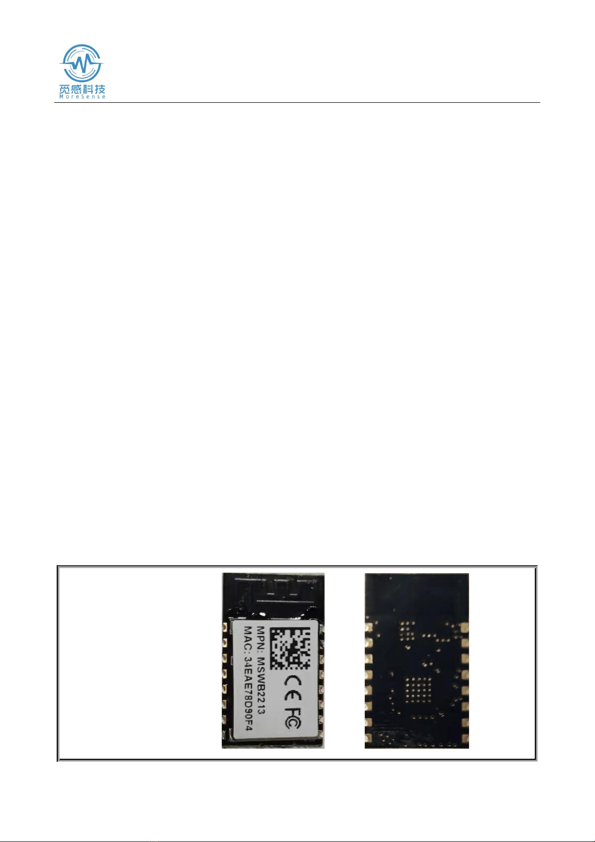
Physical Map
Built-in Antenna:

MSWB2213
Shenzhen MoreSense Technology Co., Ltd.
2
2 System Block Diagram

MSWB2213
Shenzhen MoreSense Technology Co., Ltd.
3
3 Product Features
•Support IEEE802.11b/g/n protocol;
•Support 20MHz and 40MHz bandwidth in 2.4GHz band;
•Support 1T1R mode,data rate up to 150Mbps;
•4 x Virtual Wi-Fi Interfaces •Support infrastructure network (Infrastructure BSS)
Station mode,SoftAP mode,Station+SoftAP mode and promiscuous mode;
•Bluetooth Low Energy (BluetoothLE):Bluetooth5,Bluetoothmesh;
•The rate supports 125Kbps,500Kbps,1Mbps;
•Advertising Extensions;
•Multiple Advertisement Sets;
•Channel Selection Algorithm#2);
•32-bit RISC-V single-core processor with a main frequency of up to
160MHz;
•384KBROM;
•400KBSRAM (in which 16KB is dedicated to cache);
•8KBRTCSRAM;
•Embedded Flash 4M.

MSWB2213
Shenzhen MoreSense Technology Co., Ltd.
4
4 Key Application
• Security and Smart Surveillance:Cameras...
• Smart Home:smart lighting,smart buttons,smart sockets,indoor positioning
•Industrial Automation:industrial robots,Mesh networking,human-machine interface,industrial bus
applications
• Healthcare:health monitoring,baby monitor
• Consumer Electronics:smart watches,smart bands – OTT TV boxes,set top box devices – Wi-Fi
and Bluetooth speakers,toys with data upload and proximity sensing toys
•Smart Agriculture:smart greenhouse,smart irrigation,agricultural robots
• Retail Catering: POS systems,service robots,cloud printers
• Universal Low-powered IoT data logger
5 Parameter for MSWB2213
Type
Parameter
Value
WIFI
Parameter
Certification Standards
FCC/CE/SRRC/RoHS
Wireless Standards
802.11 b/g/n
Frequency Range
2.412GHz-2.462GHz
Transmit Power
802.11b: +16dBm(@11Mbps)
802.11g: +14dBm(@54Mbps)
802.11n: +13dBm(@HT20,MCS7)
Receiver Sensitivity
802.11b: -87dBm (@11Mbps,CCK)
802.11g: -87dBm (@54Mbps,OFDM)
802.11n: -85dBm (@HT20,MCS7)
Antenna
MSWB2213:
Built-in: PCB antenna

MSWB2213
Shenzhen MoreSense Technology Co., Ltd.
5
Bluetooth
Parameters
Wireless Protocol
BLE5.0
Frequency Range
2.402GHz-2.480GHz
Transmit Power
-1.5dbm
Receiver Sensitivity
-90dBm
Hardware
Parameters
Data Interface
UART
GPIO,SPI
Operating Voltage
3.0~3.6V
Working Current
Peak(continuous transmission): 260mA
Average (STA,connected and standby): 24mA
(DTIM1)
Average (STA,1KB/s): 54mA
Average (AP): 85mA
Operating Temperature
-40℃- 85℃
Storage Temperature
-40℃- 125℃
Humidity
<85%
DIM.
MSWB2213:
22mm x 13.5mm x 3mm
Software
Wireless Network Type
STA/AP/AP+STA/BLE5.0
Security Mechanism
WEP/WPA-PSK/WPA2-PSK
Encryption Type
WEP64/WEP128/TKIP/AES

MSWB2213
Shenzhen MoreSense Technology Co., Ltd.
6
6 Pin Definition
Parameters
Upgrade Firmware
Local Wireless
Remote upgrade
Customization
Development
Provide SDK for customer’s 2nd development
Network Protocol
IPv4,TCP/UDP/HTTP/MQTT
User Configuration
AT+ command set,Web page
Android/iOS terminal
Smart Link smart configuration APP

MSWB2213
Shenzhen MoreSense Technology Co., Ltd.
7
Table.1 MSWB2213 Pin Function Definition
Pin
Name
Type
Description
1
IO4
I/O/T
GPIO4,if it does not use-NC
2
IO5
I/O/T
GPIO5,if it does not use-NC
3
IO6
I/O/T
GPIO6,if it does not use-NC
4
I07
I/O/T
GPIO7,if it does not use-NC
5
UART0
O
3.3V Communication Serial Port 0 Output
GPIO18
6
UART0
I
3.3V Communication Serial Port 0 Input
GPIO19
7
UART0_CTS
I/O/T
GPIO8,if it does not use-NC
can do PWM0 function
8
UART0_RTS
I/O/T
GPIO9,if it does not use-NC
can do PWM1 function
9
IO2
I/O
GPIO2,ADC function
10
Module Reset
I
Low active hardware reset input pin,there has
internal reset circuit,external pull-up resistance is
not allowed,avoiding prolong the reset time and
cause abnormal startup.
11
Module Startup Instructions
(can be configured as
GPIO3)
I/O/T
"0" - complete startup;
"1" - do not complete startup;
if it does not use-NC
GPIO3,can do PWM2 function

MSWB2213
Shenzhen MoreSense Technology Co., Ltd.
8
12
Restore Default
Configuration(can be
configured as GPIO10)
I/O/T
GPIO10,can do PWM3 function
13
IO20
I/O/T
Debug_RX GPIO20
14
1021
I/O/T
Debug_TX GPIO21
15
+3.3V Power Supply
Power
16
Ground
Power
I:Input O:Out T:It can be set as high impedance.

MSWB2213
Shenzhen MoreSense Technology Co., Ltd.
9
7 Module Dimension
Unit: Millimeter (mm)
8 Name Rules

MSWB2213
Shenzhen MoreSense Technology Co., Ltd.
10
9 Precautions
Precautions
MSMB2213 supports built-in antenna option.When customers chooses built-in antennas,they
need to observe the following precautions for built-in antennas and general rules for modules
placement:
•On the user's PCB board,the area corresponding to the strip area (MSWB2213:22.5x13.5mm) in
the picture above cannot place components and lay GND;
•The antenna should be kept away from metal at least 10mm away from the surrounding high
components;
•The antenna part cannot be blocked by the metal casing,and the plastic casing needs to be at least
10 mm away from the antenna;
•MoreSense recommends that the MSWB2213 module be placed in the following areas of the user
board,which aimed to reducing the impact on the antenna and wireless signals.At the same time,
please ask MoreSense for technical support to assist in the placement of the module and the layout
design of related areas.

MSWB2213
Shenzhen MoreSense Technology Co., Ltd.
11
10 Hardware Typical Application

MSWB2213
Shenzhen MoreSense Technology Co., Ltd.
12
11 Package Information
11.1 Recommended Reflow Soldering Profile
Figure 1.Thermal Reflow Profile
Table 1.Reflow Data
Note::
1.It is recommended to use a nitrogen re-flux furnace;
2.The oxygen content is less than 300ppm.
No.
Program
Temp. (℃)
Time(S)
1
Re-fluxing Time
Above 220℃
35~55S
2
Peak Temp.
Highest 260℃

MSWB2213
Shenzhen MoreSense Technology Co., Ltd.
13
11.2 Instruction
A. Sealed storage period:12 months in an environment with a temperature of less than 30°C
and a relative humidity of less than 60%.
B.Be re-baked before using if the window time exceeds 168 hours after unpacking.
C. Recommended to use nitrogen filling method for baking.
D. Recommended to use nitrogen filling method.
E, Baking and rework requirements for this model:125±5℃, 24 hours.
F. Recommended storage conditions ≦10%,relative humidity under vacuum packaging.
G.If the SMT process requires to pass twice reflow ovens:
①TOP Surface②BOT Surface
Situation 1:The WIFI module is designed on the TOP surface of the customer's PCB.The the
TOP surface needs to be baked when the TOP surface has not been produced after the BOT
surface has been finished 168 hours (window time).
Situation 2;The WIFI module is designed on the BOT side of the customer's PCB and
follows the normal baking rules.
Note:The window time means 168 hours from the end of the last baking to the beginning of
the next reflow.
11.3 MSWB2213X Package Method
Reel Packaging
Dim.:340*340*50 mm

MSWB2213
Shenzhen MoreSense Technology Co., Ltd. 14
12 FCC WARNING
This device complies with part 15 of the FCC Rules. Operation is subject to the following two
conditions:
Any changes or modifications not expressly approved by the party responsible for compliance
could void the user's authority to operate the equipment.
NOTE: This equipment has been tested and found to comply with the limits for a Class B digital
device, pursuant to Part 15 of the FCC Rules. These limits are designed to provide reasonable
protection against harmful interference in a residential installation. This equipment generate, uses and
can radiate radio frequency energy and, if not installed and used in accordance with the instructions,
may cause harmful interference to radio communications. However, there is no guarantee that
interference will not occur in a particular installation. If this equipment does cause harmful
interference to radio or television reception, which can be determined by turning the equipment off
and on, the user is encouraged to try to correct the interference by one or more of the following
measures:
-- Reorient or relocate the receiving antenna.
-- Increase the separation between the equipment and receiver.
-- Connect the equipment into an outlet on a circuit different from that to which the receiver is
connected.
-- Consult the dealer or an experienced radio/TV technician for help.
instructions for host product manufacturers according to KDB 996369 D03 OEM Manual
v01
2.2 List of applicable FCC rules
The MSWB2213 is an BT Module with GFSK modulation and WIFI Module with DSSS and
OFDM. BT module operates on the 2402MHz~2480MHz band and WIFI Module operates on the
2412MHz~2462MHz.
FCC part 15.247 standard
This device complies with part 15 of the FCC Rules. Operation is subject to the condition that this device
does not cause harmful interference
(1) this device may not cause harmful interference, and (2) this device must accept any interference
received, including interference that may cause undesired operation.

MSWB2213
Shenzhen MoreSense Technology Co., Ltd. 15
2.3 Specific operational use conditions
The EUT is a BT/WIFI Module
BT/WIFI Antenna Type: PCB Antenna
BT/WIFI Antenna gain: 1.5dBi
The module can be used for mobile or applications with the maximum Ant 1.5dBi; The host
manufacturer installing this module into their product must ensure that the final composit product
complies with the FCC requirements by a technical assessment or evaluation to the FCC rules,
including the transmitter operaition. The host manufacturer has to be aware not to provide
information to the end user regarding how to install or remove this RF module in the user's manual of
the end product which integrates this module. The end user manual shall include all required
regulatory information/warning as show in this manual.
2.4 Limited module procedures
not applicable; Single Modular Approval Request
2.5 Trace antenna designs
Not applicable;
2.6 RF exposure considerations
To maintain compliance with FCC’s RF Exposure guidelines, This equipment should be
installed and operated with minimum distance between 20cm the radiator your body: Use only the
supplied antenna.
2.7 Antennas
The MSWB2213 is an BT/WIFI Module beams signals and communicates with its antenna,
which is PCB Antenna. The PCB Antenna gain is 1.5dBi. The module shall be only used with the
internal antenna(s) that has been originally tested and certified with this module.The antenna must be
either permanently attached or employ a 'unique' antenna coupler. As long as the conditions above
are met, further transmitter test will not be required. However, the host manufacturer is still
responsible for testing their end-product for any additional compliance requirements required with
this module installed (for example, digital device emissions, PC peripheral requirements, etc.).

MSWB2213
Shenzhen MoreSense Technology Co., Ltd. 16
2.10 Additional testing, Part 15 Subpart B disclaimer
The modular transmitter is only FCC authorized for FCC Part 15 Subpart C 15.247 & 15.207 &
15.209 and that the host product manufacturer is responsible for compliance to any other FCC rules
that apply to the host not covered by the modular transmitter grant of certification. If the grantee
markets their product as being Part 15 Subpart B compliant (when it also contains unintentional-
radiator digital circuity), then the grantee shall provide a notice stating that the final host product still
requires Part 15 Subpart B compliance testing with the modular transmitter installed.
ATTENTION
This device is intended only for OEM integrators under the following conditions:
1) The antenna must be installed such that 20 cm is maintained between the antenna and users,
and
2) This device and its antenna(s) must not be co‐located with any other transmitters except in
accordance with FCC multi‐transmitter product procedures. Referring to the multi‐transmitter
policy, multiple transmitter(s) and module(s) can be operated simultaneously without C2P.
3) For all products market in US, OEM has to limit the Operating Frequency:
2412-2462 MHz /2402-2480MHz by supplied firmware programming tool. OEM shall not supply
any tool or info to the end‐user regarding to Regulatory Domain change.
2.8 Label and complianceinformation
Host product manufacturers need to provide a physical or e-label stating "Contains FCC ID:
2A86J-MSWB2213"with their finished product.
2.9 Information on test modes and additional testingrequirements
Data transfer module demo board can control the EUT work in RF test mode at specified test
channel.Additional testing, Part 15 Subpart B disclaimer.The module without unintentional-radiator
digital circuit, so the module does not required an evaluation by FCC Part 15 Subpart B. The host
should be evaluated by the FCC Subpart B.
Table of contents
Popular Control Unit manuals by other brands

Scantech
Scantech MA Series Operation manual

ADLINK Technology
ADLINK Technology SMARC LEC-PX30 user guide

UTC Fire and Security
UTC Fire and Security KiddeFire Systems ARIES NETLink BACnet user guide

DNF Controls
DNF Controls 2034CL-L-PBIO user manual

BURG-WACHTER
BURG-WACHTER secuENTRY pro 7071 RELAY Instructions for use

Advantech
Advantech PCM-3116 Startup manual

RTL
RTL Scorpion II C-90 MASH TL-3 Vertical TMA Assembly Manual and Mounting Instruction Guide

GEA
GEA VARIVENT Vacuum Valve V operating instructions

WAGO
WAGO 750-564 manual

Automated Logic
Automated Logic G4106 Technical instructions

VXI Technology
VXI Technology VM1548C user manual

AQUATROL
AQUATROL AQT-275 Service manual