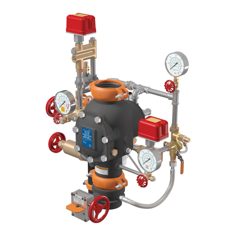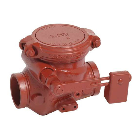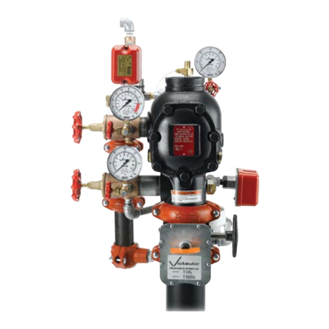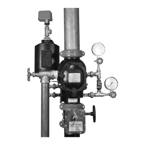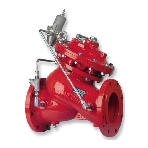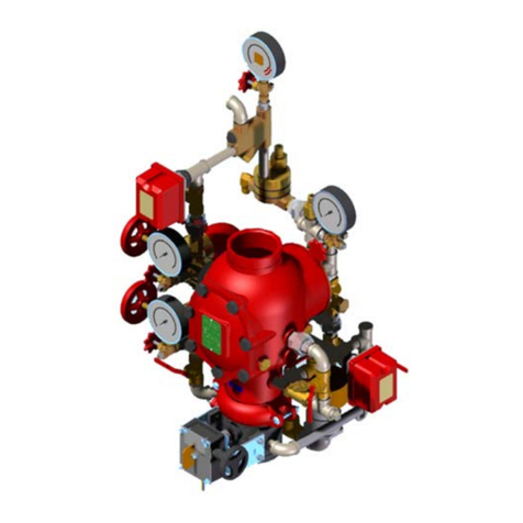
I-869E-3D / 869E-3D On-Off Deluge Valve / Installation, Maintenance, and Testing Manual
INSTALLATION
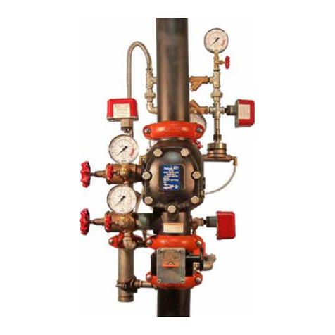
Subject to all other instructions, drawings and technical specifications
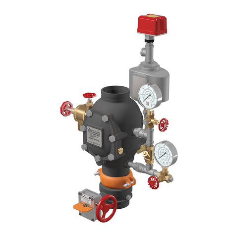
that describe the 869E-3D deluge valve, install in their proper positions
the components comprising the deluge trim package, according to the
drawing relevant to the specific type, hereby enclosed.
Install also the additional accessories, which appear in the drawing and
which must be installed as shown in the drawing, although they are not
packed together with the deluge valve itself.
Any deviation in trim size or arrangement may adversely affect the proper
operation of the deluge valve.
Refer also to NFPA 13 or the applicable installation standards, codes and
relevant authorities.
1. Allow enough room around the valve assembly for any adjustments
and future maintenance/disassembly work.
2. Before the valve is installed, flush the pipeline to remove any
dirt, scale, debris, etc. Failure to do this might render the valve
inoperable.
3. Listed indicating valves should be installed upstream and
downstream of the the 869E-3D deluge valve in order to allow for
future maintenance.
4. Install the valve in the pipeline with the valve flow arrow on the body
casting in the proper direction. Use the lifting eye provided on the
main valve cover for lifting and lowering the valve.
5. The 869E-3D deluge valve is intended for horizontal or vertical
installation. Ensure that the valve is positioned so that the actuator
can be easily removed for future maintenance.
6. Install also the additional accessories that appear in the drawing,
and which must be installed as shown in the schematic drawing.
7. Connect the electric wiring of the solenoid valve (Figure 1, call out
8) to the electric control system and the control panel according to
the supplied electrical wiring diagram.
8. When using a pressure control switch, connect the pressure
control switch to the electric control system and the control panel
according to the supplied electrical wiring diagram
9. After installation, carefully inspect/correct any damaged
accessories, piping, tubing, or fittings.
10. Any deviation in trim size or arrangement that is not authorized by a
representative of Victaulic may adversely affect the proper operation
of the deluge valve. Refer also to NFPA 13 or the applicable
installation standards, codes, or relevant authorities.
11. The deluge valve and trim must be installed only in areas where
they will not be subjected to freezing temperatures.
12. All initiating devices (detectors) and indicating appliances, as well
as the system control panel, must be compatible for use with the
particular deluge system.
EQUIVALENT LENGTH
Deluge valve equivalent length value (steel pipe), for use in hydraulically
calculated systems.
Valve Size
Equivalent Length Value
Feet/Meters
2” 30
9.1
2½” 40
12.1
3” 45
13.7
4” 46
14
6” 90
27.4
8” 150
45.7
10” 354
108
OPTIONAL EQUIPMENT
If required, provide an alarm pressure switch, to either activate an
electric alarm, or shut down desired equipment. Connect it according to
the manufacturer’s instructions.
PLACING IN SERVICE/RESETTING THE SYSTEM
1. Place the control/panel detector circuit in service.
2. De-energize the solenoid valve (Figure 1, call out 8) by resetting the
electric control panel.
3. Ensure that the emergency release valve (Figure 1, call out 5) is
closed.
4. Ensure that the drain valve is in a closed position.
5. Open the priming line ball valve (Figure 2, call out 3), which
charges the pressure supply to the HRV. No water should flow from
solenoid valve (Figure 2, call out 6) or from the HRV venting tube.
Allow pressurized water to fill the top chamber of the deluge valve.
6. Open the main supply valve (Figure 1, call out 9) slowly. The main
valve will gradually close and seal. No water should flow to the system.
7. The system is now in service.
REMOVING THE SYSTEM FROM SERVICE
When taking deluge system out of service, a fire patrol should be
established in the system area. If automatic fire-alarm signaling equipment
is utilized, the proper authority should be notified that the system is being
removed from service. The insuring body and owner representative should
also be notified when the system is being taken out of service.
REMOVAL INSTRUCTIONS
1. Shut off the main supply valve (Figure 2, call out 9).
2. The priming line ball valve (Figure 2, call out 3) to the deluge valve
should be closed.
3. Open the drain valve to drain all the water from the system.
4. Release the water pressure from the top chamber of the deluge
valve by pulling the emergency release (Figure 2, call out 7), or by
tripping the electrical circuit (energize the solenoid valve (Figure 2,
call out 6).
5. If auxiliary power is used, disconnect all power supply and batteries.
6. Place “Fire Protection System Out of Service” signs in the area
protected by the system.
I-869E-3D_6 REV_A
