Morningstar SureSine 150 User manual

Installation and Operations Manual
150 W, 300 W, 700 W (12 V, 24 V, & 48 V) Models,
1,000 W &1,250 W, (24 V & 48 V) Models,
2,500 W (48 V Only) Models
September 2022 (Rev B08)
MORNINGSTAR
World’s Leading Solar Controllers &Inver ters

MS-003650
MORNINGSTAR
World’s Leading Solar Controllers &Inverters
About MorningStar:
With well over 4 million products sold in over 100 countries since 1993—functioning in some of the most
extreme environments and mission-critical applications in the world—Morningstar Corporation can truly claim
to be “the leading supplier of solar controllers and inverters.” That success is why Morningstar has had staying
power and stable management for over 27 years, along with the lowest employee turnover rate.
• Smarter digital design has been pioneered for solar components, for faster, more agile processing on-
board. This allows for the maximum performance from thehardware.
• Advanced thermal engineering is used to eliminate cooling fans—the weak link in competitors’
products.
• Finally, internal electronics are laid out for performance and longevity instead of economics—designing
for the long-term in order to achieve the industry’s lowest hardware failure rates.
For additional information about Morningstar Corporation, go to:
www.morningstarcorp.com
Disclaimer:
The specifications and descriptions contained in this document are verified to be as accurate as possible at
the time of publication. However, because Morningstar Corporation’s products and their performance are
constantly evolving, Morningstar reserves the right to make product or documentation modifications at any
time, with or without notice. Due to the wide range of applications where this product can be used, details may
vary by product version, geography, and site application.
To ensure that you have the most current version of this document, go to:
www.morningstarcorp.com/support.
To communicate any inaccuracies or omissions in this document, please fill out a contact form at:
www.morningstarcorp.com/support.
Reference document #: MS-003650. Rev B08
Contact Information:
Morningstar Corporation
8 Pheasant Run
Newtown, Pennsylvania 18940 USA
Email: [email protected]
Website: www.morningstarcorp.com
Service and Support: www.morningstarcorp.com/support
Phone: +1 215.321.4457
Copyright 2022:
This document and its contents are protected by trade secrets, patent, copyright, and other applicable laws.
Allrights are reserved. Unauthorized use is illegal.
SureSine™ is a trademark of Morningstar Corporation
MODBUS™ and MODBUS TCP/IP™ are trademarks of Modbus IDA. www.modbus-ida.org
© 2022 Morningstar Corporation. All rights reserved.

MS-003650
MORNINGSTAR
World’s Leading Solar Controllers &Inverters
IMPORTANT SAFETY INSTRUCTIONS
SAVE THESE INSTRUCTIONS - This manual contains important safety, installation, and operating
instructions for the Morningstar SureSine Inverter.
The SureSine produces voltages and currents capable of causing severe injury or death. Extreme
caution must be taken when installing and using the SureSine.
The following symbols are used throughout this manual to indicate potentially dangerous conditions
or important safety instructions.
WARNING: Indicates a potentially dangerous condition.
Failure to observe this notice could result in severe personal
injury ordeath.
CAUTION: Indicates a critical procedure for safe and proper
operation of the SureSine. Use extreme caution when
performing this task. Failure to observe this notice could result
in personal injury or equipment damage.
NOTE: Indicates a procedure or function that is important to
the safe and proper operation of the SureSine Inverter.
GENERAL SAFETY INFORMATION
Throughout this manual, NEC guidance has been provided in order to meet general safety
requirements and inform best installation practices. It is the installer’s responsibility to ensure that the
Installation complies with all local safety and code requirements.
• Read all of the instructions and cautions in the manual before starting the installation.
• Ensure that battery power has been disconnected BEFORE installing, servicing, or removing
the SureSine Inverter.
• Do not allow water to enter the SureSine.
• Avoid wearing jewelry while installing this equipment.
• Do not smoke near the battery bank.
• Ensure power connections remain tight to avoid excessive heating from a looseconnection.
• Recycle the battery when it is replaced.

MS-003650
MORNINGSTAR
World’s Leading Solar Controllers &Inverters
WIRE AND CABLE SAFETY
Proper wire type and size is required for all installations. Use only UL-listed Class B or Class C wire
rated for 300 volts and 75ºC or higher. Use stranded wire for the battery circuit and solid or stranded
wire for the AC and Ground circuits.
Copper wire is recommended instead of aluminum due to its ease of use, superior conductivity,
strength and thermal expansion properties.
WARNING: SHOCK HAZARD
• Installations must be performed by a qualified person trained in electrical safety
procedures (minimum qualification).
• All wiring must comply with local electric code requirements.
• Ensure all sources of input are disconnected before connecting ANYcabling.
WARNING: RISK OF FIRE
All over-current protection devices and wiring must be sized properly, in accordance with
US National Electric Code (NEC) or the local regulations of the country of installation.
WARNING: FIRE HAZARD
A risk of fire may exist if a 120 Vac power source is wired incorrectly to 120/240 Vac
panel containing multi-wire branch circuits.
MOUNTING, CLEARANCE, AND LOCATION SAFETY
WARNING: EXPLOSION/FIRE HAZARD
Do not install in a confined area where battery gases can accumulate. Battery gases can
create an explosion or fire hazard if ignited by a spark. Ensure the enclosure is ventilated
well enough to disperse any accumulated gases.
Do not install over an easily combustible surface, since the heat sink may get hot under
certain operating conditions.
CAUTION: EQUIPMENT DAMAGE
• Do not mount in zero-clearance compartment. Overheating may result. Ensure
adequate space around the components to ensure sufficient ventilation around the
equipment.
• Locate the SureSine on a surface that is protected from directsun, hightemperatures,
corrosive fumes, and water.
• Ensure the mounting surface is strong enough to support the weight of the inverter as
well as any other devices that may be attached to it. It may be necessary to reinforce
the surface with plywood to provide additional support for the equipment.

MS-003650
MORNINGSTAR
World’s Leading Solar Controllers &Inverters
CAUTION: HOT SURFACE/BURN HAZARD
The SureSine inverter models 700 Watts to 2,500 W can become very hot. Install the
SureSine so that it cannot be accidentally touched by anyone or anything.
BATTERY SAFETY INFORMATION
WARNING: SHOCK HAZARD
• Servicing of batteries should be performed, or supervised, by personnel
knowledgeable about batteries, and the proper safety precautions.
• Have someone nearby to assist in case of an accident.
• Carefully read the battery manufacturer’s instructions before installing / connecting to,
or removing batteries from the SureSine Inverter.
• A battery can present a risk of electrical shock or burn from large amounts of short-
circuit current, fire, or explosion from vented gases. Observe proper precautions.
• Remove watches, rings, jewelry and other metal objects before working with
batteries.
• Use tools with insulated handles and avoid placing tools or metal objects on top
ofbatteries.
• Disconnect charging source prior to connecting or disconnecting battery terminals.
• Determine if battery is inadvertently grounded. If so, remove the source of contact
with ground. Contact with any part of a grounded battery can result in electrical
shock. The likelihood of such a shock can be reduced if battery grounds are removed
during installation and maintenance (applicable to equipment and remote battery
supplies not having a grounded supply circuit).
WARNING: RISK OF EXPLOSION
• Explosive battery gases can be present during charging. Be certain there is enough
ventilation to release the gases.
• Proper disposal of batteries is required. Do not dispose of batteries in fire. Refer to
local regulations or codes for requirements. Recycle the battery when it is replaced.
• Never smoke in the battery area.
WARNING: CORROSION HAZARD/TOXIC FUMES
• Do not open or mutilate batteries. Released electrolyte is harmful to skin and may
betoxic if inhaled.
• Be very careful when working with large lead-acid batteries. Wear eye protection and
have fresh water available in case there is contact with the battery acid.
• Wear rubber gloves and boots.
• If battery acid comes into contact with the skin, wash with soap and water. If the acid
contacts the eye, flood with fresh water and get medical attention.
• Recycle the battery when it is replaced.

MS-003650
MORNINGSTAR
World’s Leading Solar Controllers &Inverters
BATTERY SAFETY INFORMATION
(Continued)
CAUTION: EQUIPMENT DAMAGE
• Ensure the battery voltage matches the DC voltage requirements of the model of
SureSine inverter to be installed.
• Ensure the battery bank consists of batteries of the same type, make and age.
• Be sure the battery electrolyte level is correct before starting charging. Do not
attempt to charge a frozen battery.
• Ensure that the charging equipment implemented in the system meets the charging
requirements for the battery bank and varied charging
• The SureSine Low Voltage Disconnect (LVD) and Low Voltage Reconnect (LVR) presets
are generally designed for lead acid batteries. Use custom LVD and LVR settings
required for the type of battery in the system and minimum desired state of charge
(SOC). Note that some battery types may not be compatible.
• Be sure the battery electrolyte level is correct before starting charging. Do not
attempt to charge a frozen battery.

MS-003650
MORNINGSTAR
World’s Leading Solar Controllers &Inverters
i
Table of Contents
1.0 Introduction................................................................................................................1
1.1 Features.................................................................................................................1
1.2 Components of the 150 W & 300 W Models ........................................................2
1.3 Components of the 700 W Models .......................................................................3
1.4 Components of the 1,000 W to 2,500 W Models .................................................4
1.5 Dimensions of the 150 W & 300 W Models ..........................................................5
1.6 Dimensions of the 700 W to 2,500 W Models.......................................................6
2.0 Installation..................................................................................................................7
2.1 Required Tools.......................................................................................................7
2.2 Additional Hardware Requirements.......................................................................7
2.3 Mounting ...............................................................................................................8
2.3.1 Safety Considerations for Mounting.........................................................9
2.3.2 Mounting Procedure...............................................................................10
2.4 Adjusting Settings ...............................................................................................11
2.4.1 DIP Switch Location................................................................................11
2.4.2 DIP Switch Configuration Options..........................................................12
2.5 Remote Switch Installation (Optional) .................................................................13
2.6 Auxiliary Power (Optional) ...................................................................................14
2.7 Inverter Wiring.....................................................................................................15
2.7.1 Terminal Torque Requirements ..............................................................15
2.7.2 Over-current Protection Requirements...................................................16
2.7.3 DC and AC Conductor Sizing Requirements..........................................17
2.7.4 Grounding and Bonding Requirements..................................................18
2.7.5 Grounding Connections .........................................................................20
2.7.6 DC Connections .....................................................................................22
2.7.7 AC Connections......................................................................................26
2.7.8 AC Wiring ...............................................................................................27
2.8 Check Wiring and Power Up ..............................................................................28
3.0 Operation .................................................................................................................29
3.1 LED Indications....................................................................................................29
3.2 AC Output Mode Switch Operation....................................................................29
4.0 Communication Options...........................................................................................30
4.1 Bluetooth.............................................................................................................31
4.1.1 To Connect the SureSine using Bluetooth..............................................31
4.1.2 SureSine Utility App................................................................................32
4.2 Ethernet (for Modbus™ TCP/IP)..........................................................................33
4.2.1 To Connect to the Internet using Modbus Protocols .............................33
4.3 EIA-485 Device Communication .........................................................................34
4.3.1 To Connect the SureSine Inverter to an EIA-485 Device........................34
4.4 USB Port ..............................................................................................................36
4.4.1 To Connect to the USB Port....................................................................36
4.5 MS-CAN (Future Feature) ....................................................................................37
4.5.1 To Connect the SureSine to another Morningstar Device......................37
4.5.2 To Connect the SureSine to a Morningstar Network..............................38
5.0 Firmware Update Procedure ....................................................................................38
6.0 Specications............................................................................................................39
Appendix A: Conductor Sizing..........................................................................................44
A.1 Stranded Copper Wire Rated for 75°C................................................................44
A.2 Solid Copper Wire Rated for 75°C ......................................................................45
A.3 Stranded Copper Wire Rated for 90°C................................................................46

MS-003650
MORNINGSTAR
World’s Leading Solar Controllers &Inverters
ii
A.4 Solid Copper Wire Rated for 90°C ......................................................................47
Appendix B: Warranty.......................................................................................................48
B.1 Claim Procedure ..................................................................................................48
B.2 Warranty Exclusions And Limitations...................................................................48
List of Figures
Figure 1: SureSine Inverters Series.................................................................................................1
Figure 2: SureSine Inverter Features (150 W & 300 W Models) .....................................................2
Figure 3: SureSine Inverter Features (700 W Models) ....................................................................3
Figure 4: SureSine Inverter Features (1,000 W to 2,500 W Models) ..............................................4
Figure 5: Dimensions - 150 W to 300 W Models ...........................................................................5
Figure 6: Dimensions - 700 W to 2,500 W Models ........................................................................6
Figure 7: Mounting Orientation .....................................................................................................8
Figure 8: Mounting Holes...............................................................................................................8
Figure 9: Minimum Clearance Requirements .................................................................................9
Figure 10: DIP Switches................................................................................................................11
Figure 11: DIP Switch Configurations ..........................................................................................12
Figure 12: Remote Switch Wiring for 150 W to 300 W Models ...................................................13
Figure 13: Remote Switch Wiring for 700 W to 2,500 W Models ................................................13
Figure 14: Auxiliary Power Terminals on 700 W to 2,500 W Models............................................14
Figure 15: Internal Grounded Neutral vs. External Grounded Neutral
(InternalNeutralGroundBondremoved) ...................................................................19
Figure 16: DC Connections on 150 W & 300 W Models with Negative Grounding....................24
Figure 17: DC Connections on 150 W & 300 W Models with Positive Grounding ......................24
Figure 18: DC Connections on 700 W to 2,500 W Models with Negative Grounding ................25
Figure 19: DC Connections on 700 W to 2,500 W Models with Positive Grounding...................25
Figure 20: AC Connections on 150 W, 300 W, & 700 W Models (with Factory Wiring) ...............26
Figure 21: AC Wiring....................................................................................................................28
Figure 22: AC Output Mode Operation and Bluetooth Activation..............................................29
Figure 23: Communication Port Locations ...................................................................................30
Figure 24: Communication using Bluetooth.................................................................................31
Figure 25: SureSine Utility App (Main Dashboard) .......................................................................32
Figure 26: Communication using Ethernet...................................................................................33
Figure 27: EIA-485/RS-232 Communications Adapter (RSC-1) ....................................................34
Figure 28: Connecting to an EIA-485 Device...............................................................................34
Figure 29: Auxiliary Power Connections (700 W, 1,000 W, 1,250 W or 2,500 W Models ONLY) .35
Figure 30: USB Port Locations......................................................................................................36
Figure 31: Communication Using MS-CAN..................................................................................37
Figure 32: Communication Using MS-CAN with Multiple Devices ..............................................38

1
INTRODUCTION
MS-003650 (Rev B08)
1.0 INTRODUCTION
The SureSine Inverter is a pure sine wave inverter for industrial and residential DC-
to-AC applications which require high quality power. The SureSine can be used as
a standalone system or as an accessory to larger systems that may include charging
sources and energy storage systems.
1.1 Features
SureSine features include:
• DC power to AC power conversion to the following output voltages:
– 120-volt/60 Hz
– 230-volt/50 Hz
• Pure sine wave conversion produces a highly efficient AC grid-quality power.
• Supports 12-volt, 24-volt, or 48-volt DC systems (dependent on model purchased).
• Extensive electronic protections ensure protection against faults and user mistakes
such as short circuits, overloads, high temperatures, and low voltage disconnects.
Recovery from most faults is automatic.
• Two LEDs provide important information to the user regarding battery status and
AC output.
• Remote ON/OFF capability.
• Eight DIP switches provide easy adjustment of several system parameters.
• Multiple communication options.
– Mobile devices can connect through Bluetooth
– Other network devices can connect through Ethernet and/or EIA-485
– FUTURE FEATURE: The SureSine Inverter can pair with other Morningstar
products that feature MS-CAN Communication for control, adjustments, and
monitoring performance
Figure 1: SureSine Inverters Series

2MS-003650 (Rev B08)
INTRODUCTION
1.2 Components of the 150 W & 300 W Models
Figure 2 shows the components included with the 150 and 300 W models.
Figure 2: SureSine Inverter Features (150 W & 300 W Models)

3
INTRODUCTION
MS-003650 (Rev B08)
1.3 Components of the 700 W Models
Figure 3 shows the components included with the 700 W models.
Figure 3: SureSine Inverter Features (700 W Models)

4MS-003650 (Rev B08)
INTRODUCTION
1.4 Components of the 1,000 W to 2,500 W Models
Figure 4 shows the components included with the 1,000 W to 2,500 W models.
Figure 4: SureSine Inverter Features (1,000 W to 2,500 W Models)

5
INTRODUCTION
MS-003650 (Rev B08)
1.5 Dimensions of the 150 W & 300 W Models
Figure 5: Dimensions - 150 W to 300 W Models

6MS-003650 (Rev B08)
INTRODUCTION
1.6 Dimensions of the 700 W to 2,500 W Models
Figure 6: Dimensions - 700 W to 2,500 W Models

7
INSTALLATION
MS-003650 (Rev B08)
2.0 INSTALLATION
Included in the box:
• Mounting Screws (#10 x4)
• CAN Terminal resistor
• Terminal block connector (for Modbus, Remote Switch, Auxiliary Power)
2.1 Required Tools
WARNING: SHOCK HAZARD
This product can produce hazardous voltage. Use insulated tools while working
with this equipment.
The minimum required tools include the following. Additional tools may be required
depending on the site application.
• Wire cutters/strippers
• Drill and 1/8” (3 mm) drill bit
• #2 Philips and 3/16 (5 mm) & 1/8” (3.8 mm) Flat-head screwdrivers
• Multimeter
• Crimping Tool
• Wrench
2.2 Additional Hardware Requirements
Depending on the type of installation, additional hardware may be required. This
hardware is NOT provided with the SureSine Inverter. These types of components
include, but are not limited to:
• Battery or battery bank
– Ensure the battery voltage matches the DC voltage requirements of the model
of SureSine inverter to be installed.
– Ensure the battery bank is comprised of batteries of the same type, make,
andage.
• All DC and ground cables
• AC wiring for 700 W to 2,500 W models only
• Sub panels, circuit breakers, fuses Ground Fault Disconnects etc.
• Primary Earth Ground connection (e.g., ground rod)
• Remote Switch (Optional)
Consult the system design diagrams to determine the exact requirements for
theinstallation.

8MS-003650 (Rev B08)
INSTALLATION
2.3 Mounting
The SureSine may be mounted horizontally on a flat surface (like a table) or vertically
(on a wall). If mounted vertically (on a wall), the inverter can be mounted either
portrait style or landscape style. Ensure that there is enough space inside the
enclosure for the wiring and ventilation. For optimal ventilation and cooling, mount in
portrait style orientation.
Figure 7: Mounting Orientation
Four Keyhole slots are provided to secure the inverter to the mounting surface.
.
Figure 8: Mounting Holes

9
INSTALLATION
MS-003650 (Rev B08)
2.3.1 Safety Considerations for Mounting
WARNING: EXPLOSION/FIRE HAZARD
Do not install in a confined area where battery gases can accumulate. Battery
gases can create an explosion or fire hazard if ignited by a spark. Ensure the
enclosure is ventilated well enough to disperse any accumulated gases.
Do not install over an easily combustible surface, since the heat sink may get hot
under certain operating conditions.
CAUTION: EQUIPMENT DAMAGE
• Do not mount in zero-clearance compartment. Overheating may result.
Ensure adequate space around the components to ensure sufficient
ventilation around the equipment.
• Locate the SureSine on a surface that is protected from directsun,
hightemperatures, corrosive fumes, and water.
• Ensure the mounting surface is strong enough to support the weight of the
inverter as well as any other devices that may be attached to it. It may be
necessary to reinforce the surface with plywood to provide additional support
for the equipment.
CAUTION: HOT SURFACE/BURN HAZARD
The SureSine inverter models 700 Watts to 2,500 W can become very hot. Install
the SureSine so that it cannot be accidentally touched by anyone.
Figure 9: Minimum Clearance Requirements

10 MS-003650 (Rev B08)
INSTALLATION
2.3.2 Mounting Procedure
To secure the inverter to the mounting surface:
1. Place the SureSine on the surface where it will be mounted and
determine where the wires will enter/exit.
• Be sure there is sufficient bending room for the wires and other
auxiliary connections, as required by local code.
• Verify that the mounting screws will not penetrate wires or other
objects located on the opposite side of the surface.
• Ensure the surface is strong enough to support the weight of the
inverter and anything else mounted on it. It may require additional
support, such as a sheet of plywood.
2. With a pencil or pen, mark the mounting hole locations.
3. With a drill and 1/8” (3 mm) bit, drill pilot holes for each of the four
mounting screw locations marked on the mounting surface.
4. Place the SureSine onto the surface and align the mounting feet holes
with the four pilot holes. Use the #10 screws (included) to secure the
SureSine to the surface.

11
INSTALLATION
MS-003650 (Rev B08)
2.4 Adjusting Settings
The SureSine has eight (8) DIP Switches that allow for adjusting specific operational
parameters for the inverter. Each switch has an ON/OFF position. See Section 2.4.2
on page12 for details on specific settings.
IMPORTANT:
Check that the DIP Switches are properly configured for the designed installation
prior to installing the inverter.
2.4.1 DIP Switch Location
The DIP switches are located on the DC side of allmodels.
Figure 10: DIP Switches

12 MS-003650 (Rev B08)
INSTALLATION
2.4.2 DIP Switch Configuration Options
DIP Switches control the operational functions of the inverter as follows.
Thedefault position for these switches is OFF.
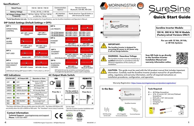
Table 1: DIP Switch Conguration
DIP
Switch Function Status Control Content
1 Operational
Control
OFF AC Output is controlled by the Remote ON/OFF Switch
ON AC Output is controlled by the communication command (digital command).
2 Alarm Sounds OFF Beeper OFF
ON Beeper ON
3 Not Used OFF Not Used - Default is OFF
ON Not Used - Default is OFF
4 Low Voltage
Disconnect
OFF CUSTOM. LVD is set according to the factory default values and the non-default
values can be modified through RS485 communication port or Bluetooth App.
ON PRESETS. LVD is set with the #5 DIP Switch values and cannot be modified.
5 Low Voltage
Disconnect
PRESETS
(I.E.,Default)
For 12 V
(24 V or 48 V)
Systems
OFF • Alarms when DC Input voltage is 10.8 V, (21.6 V or 44.4 V)
• Disconnects AC Output when DC Input voltage is 10.5 V (21.0 V or 42.0 V),
and
• Restarts AC Output when DC Input voltage is 11.6 V (25.2 V or 46.4 V)
ON • Alarms when DC Input voltage is 11.8 V (23.6 V or 48.4 V),
• Disconnects AC Output when DC Input voltage is 11.5 V (23.0 or 46V), and
• Restarts AC OUTPUT when DC Input voltage is 12.6 V (25.2 V or 50.4 V).
6 Standby Mode OFF AC Output is always ON
ON AC Output is OFF unless a load > 8 W is detected
7 Not Used OFF Not Used - Default is OFF
ON Not Used - Default is OFF
8 Bluetooth
Communication
OFF Bluetooth Disabled
ON Bluetooth Enabled
Figure 11: DIP Switch Congurations
This manual suits for next models
5
Table of contents
Other Morningstar Inverter manuals

Morningstar
Morningstar SureSine 150 W User manual

Morningstar
Morningstar SureSine-300 Setup guide

Morningstar
Morningstar SureSine 150 W User manual

Morningstar
Morningstar TRISTAR TS-MPPT-60 Instruction Manual

Morningstar
Morningstar SUNSAVER SS-6-12V User manual

Morningstar
Morningstar SureSine 150 W User manual

Morningstar
Morningstar ProStar PS-15M User manual

Morningstar
Morningstar Tristar TS-MPPT-60M User manual

Morningstar
Morningstar TS-MPPT-60-600V-48-DB-TR User manual

Morningstar
Morningstar SureSine 150 W User manual