Mortara Instrument X-Scribe II User manual

MIS-11-151-00 Rev 1 Page 1 of 26
.
Instructions for Assembling
X-Scribe II Cart
COPYRIGHT 2001
BY MORTARA INSTRUMENT, INC.
7865 N. 86TH STREET
MILWAUKEE, WISCONSIN 53224
MORTARA INSTRUMENT IS A REGISTERED TRADEMARK OF MORTARA INSTRUMENT, INC.

MORTARA INSTRUMENT SPECIFICATION
MIS-11-151-00 Rev. 1
© 2001 Mortara Instrument, Inc. CONFIDENTIAL PAGE 2 OF 26
Table of Contents
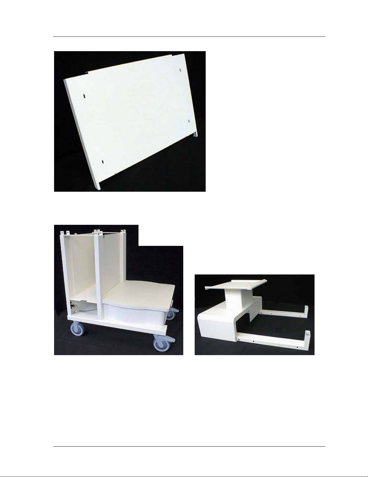
COMPONENTS ........................................................................ 3
Tools required for Assembly:.................................................................................. 3
Material Supplied with Cart Assembly .................................................................... 3
SECTION 1 -- ASSEMBLY OF CART...................................... 7
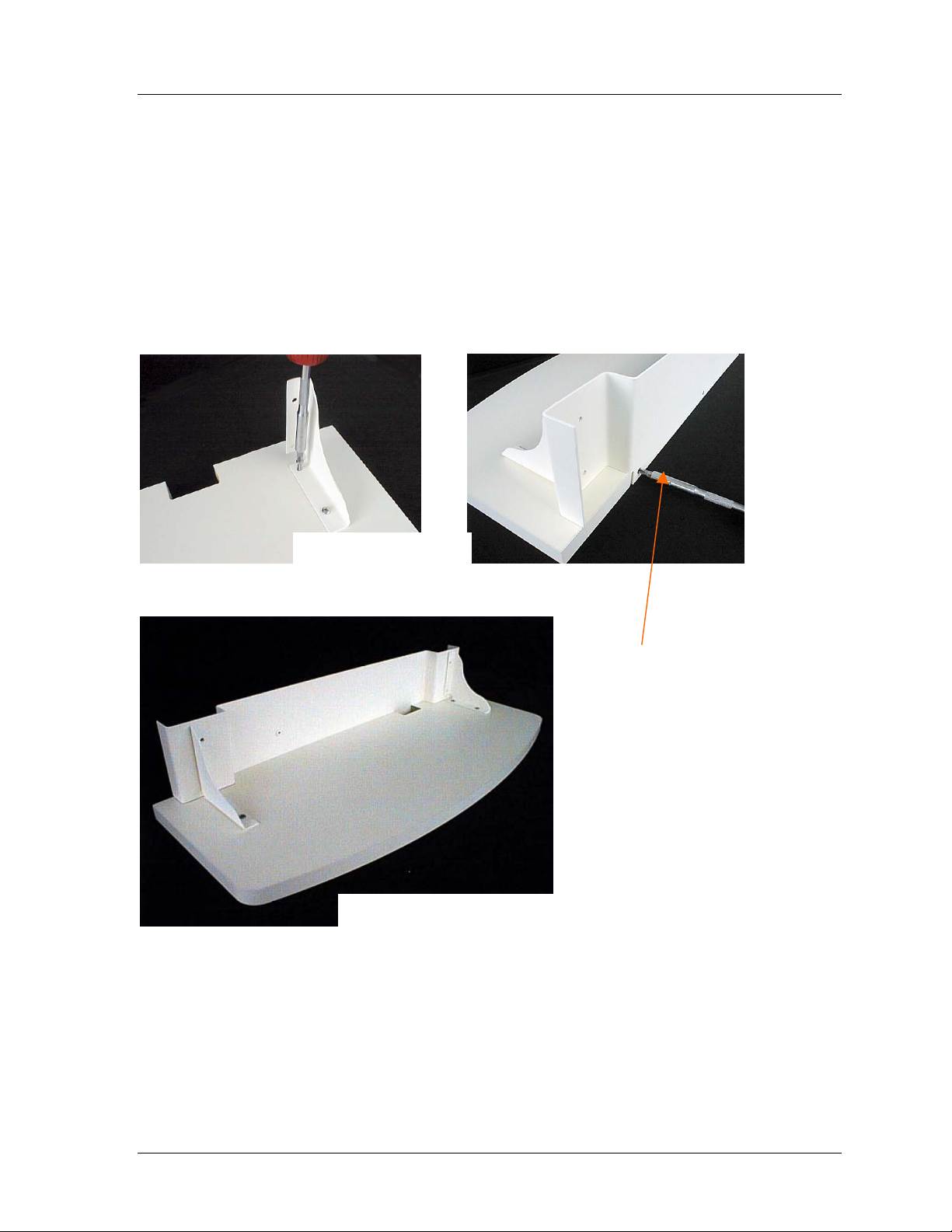
STEP 1 Keyboard Shelf Assembly ........................................................................ 7
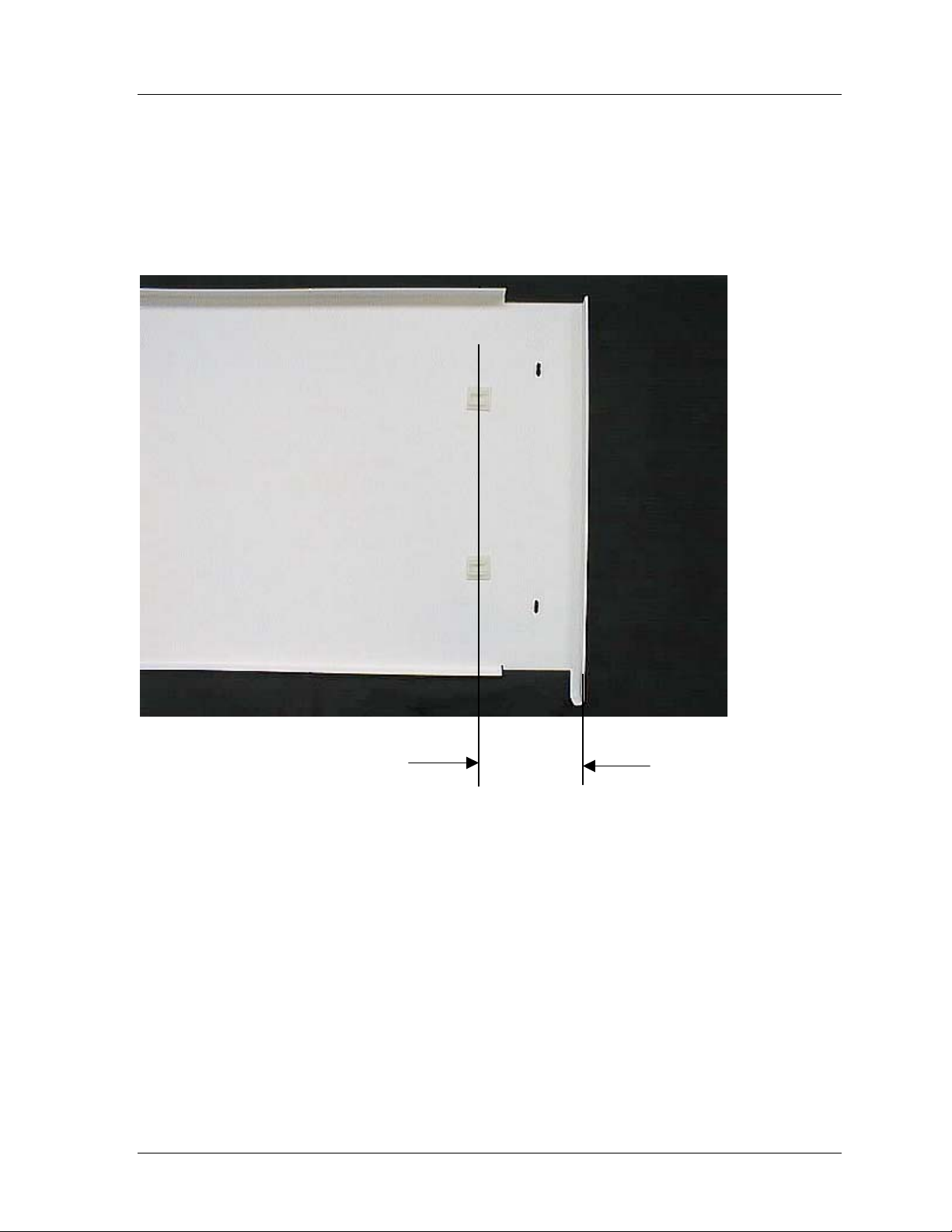
STEP 2 Placement of Cable Clips.......................................................................... 8
STEP 3 Unpacking Upper Column and Base Assembly ........................................ 9
STEP 4 Installation of Printer and Keyboard Shelf ............................................... 10
STEP 5 Installing Castors .................................................................................... 11
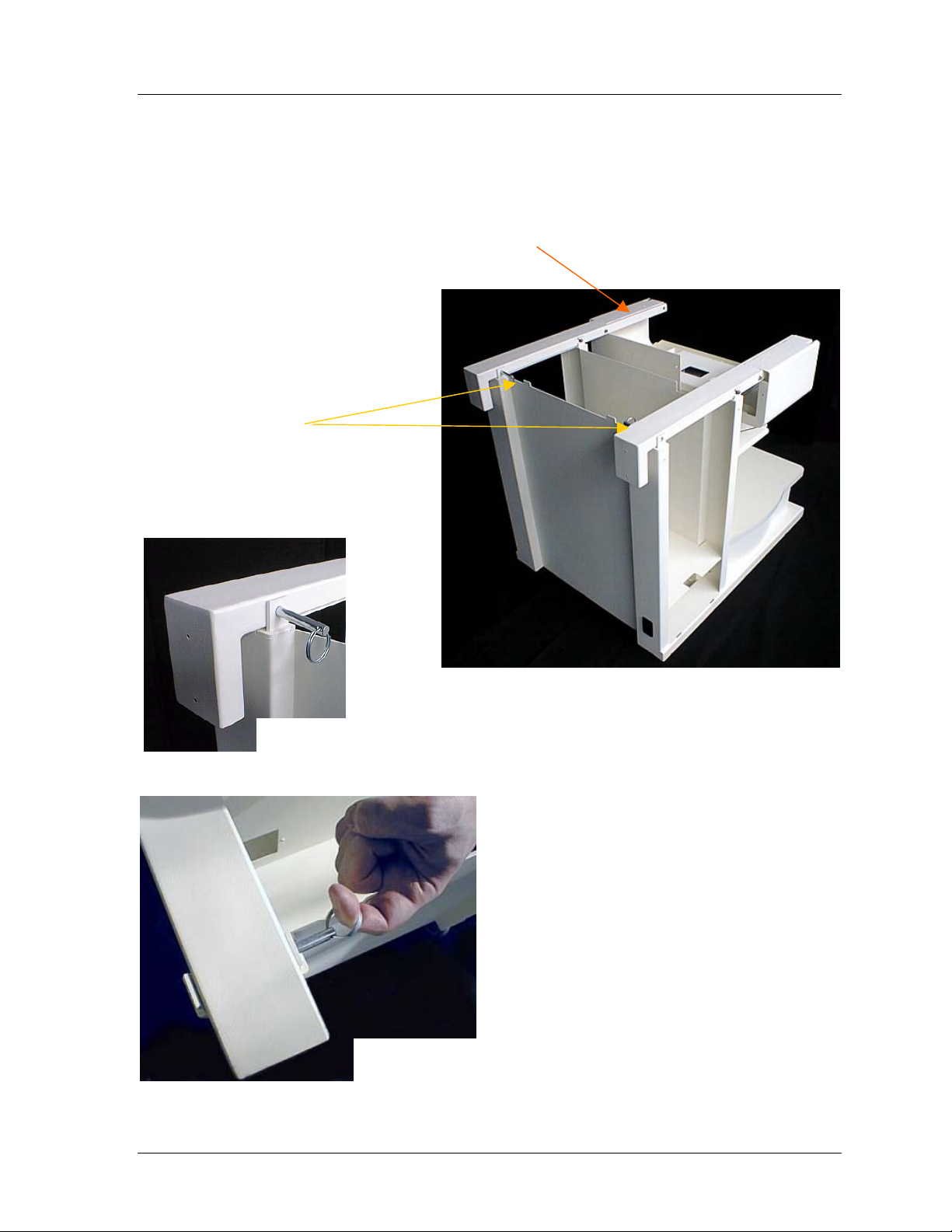
STEP 6 Attaching Upper Column with Base ........................................................ 12
STEP 7 Ground Strap .......................................................................................... 14
STEP 8 Inserting the Support Pins for the Writing Shelf ...................................... 15
SECTION 2 -- INSTALLATION OF COMPUTER
COMPONENTS ................................................................. 17
STEP 1 Installing Isolation Transformer ............................................................... 17
STEP 2 Installing Computer ................................................................................. 18
STEP 3 Routing cables ........................................................................................ 18
STEP 4 Installing Monitor..................................................................................... 19
STEP 5 Monitor Cables........................................................................................ 19
STEP 6 Installing Side Cover ............................................................................... 20
STEP 7 Installing Isolation Transformer Panel..................................................... 20
STEP 8 Installing Rear Cover............................................................................... 21
COMPLETED X-SCRIBE II SYSTEM..................................... 22
OPTIONAL ACCESSORIES .................................................. 23
COVER SHELF INSTALLATION ........................................... 23
COMPONENTS.................................................................................................... 23
Tools required for Assembly:................................................................................ 23
Material Supplied with Cover Shelf Installation..................................................... 23
Adjustment of Cover Shelf.................................................................................... 25
M12 Strain Relief Installation ............................................... 26
COMPONENTS.................................................................................................... 26
Tools required for Assembly:................................................................................ 26
Material Supplied for M12 Patient Cable Installation ............................................ 26

MORTARA INSTRUMENT SPECIFICATION
MIS-11-151-00 Rev. 1
© 2001 Mortara Instrument, Inc. CONFIDENTIAL PAGE 3 OF 26
COMPONENTS
Tools required for Assembly:
1 - Phillips screwdriver #2
1 - Phillips screwdriver #4
1 - Thin flat blade screwdriver, 3/16” or 5mm in width
1 - 10 mm open ended or combination wrench
Material Supplied with Cart Assembly
2 Swivel Castors
2 Non-Swivel Castors
1 Upper Column
1 Base Assembly
Plus the following Hardware:
ITEM 1
1/4" WING NUT
2 EA.
ITEM 2
1/4" SLOTTED TRUSS
HEAD SCREW
2 EA.
ITEM 3
#6 - 3/4" 82°
COUNTERSUNK FLAT
3 EA.
HEAD PHILLIPS SCREW
ITEM 4
#8 - 5/8" PAN HEAD
PHILLIPS SHEET METAL
SCREW
4 EA.
ITEM 5
M6 STAR WASHER
4 EA.
ITEM 6
M8 x 16mm PAN HEAD
PHILLIPS MACHINE SCREW
16 EA.
ITEM 7
M4 x 8 mm PAN HEAD
PHILLIPS MACHINE SCREW
19 EA.
ITEM 8
3/16" x 3/8" LONG
SHOULDER BOLT
4 EA.
ITEM 9
1/4" FLAT WASHER
2 EA.
ITEM 10
M6 HEX NUT
2 EA.
ITEM 11
5/16" x 3" DETENT RING PIN
2 EA.
ITEM 12
CABLE CLIP
2 EA.
ITEM 14
MONITOR LOCK CLIP
2 EA.
ITEM 13
GROUND STRAP
(Not to Scale)
1 EA.

MORTARA INSTRUMENT SPECIFICATION
MIS-11-151-00 Rev. 1
© 2001 Mortara Instrument, Inc. CONFIDENTIAL PAGE 4 OF 26
Keyboard Shelf
Item 15
Keyboard Shelf Support
Item 17
Writing Shelf
Item 18
Gusset (2 ea.)
Item 16

MORTARA INSTRUMENT SPECIFICATION
MIS-11-151-00 Rev. 1
© 2001 Mortara Instrument, Inc. CONFIDENTIAL PAGE 5 OF 26
Side Cover
Item 19
Rear Cover
Item 22
Column Cover
Item 21
Isolation Transformer Cover
Item 20

MORTARA INSTRUMENT SPECIFICATION
MIS-11-151-00 Rev. 1
© 2001 Mortara Instrument, Inc. CONFIDENTIAL PAGE 6 OF 26
Printer Shelf
Item 23
Base Assembly Upper Column Assembly
Item 24 Item 25
Castors shown for
reference of position.

MORTARA INSTRUMENT SPECIFICATION
MIS-11-151-00 Rev. 1
© 2001 Mortara Instrument, Inc. CONFIDENTIAL PAGE 7 OF 26
SECTION 1 -- ASSEMBLY OF CART
STEP 1 Keyboard Shelf Assembly
Lay the Keyboard Shelf (Item 15) on a flat surface with the side with 4 holes
facing up. Position the Gussets (Item 16) as shown, and affix with Qty 4, #8 x
5/8” Pan Head Phillips Sheet Metal Screws (Item 4).
Position the Keyboard Shelf
Support (Item 17) as shown, and
install Qty 3, #6 x 3/4” 82°
Countersunk Flat Head Phillips
Screws (Item 3).
Attaching Gussets
Keyboard Shelf Assembly complete

MORTARA INSTRUMENT SPECIFICATION
MIS-11-151-00 Rev. 1
© 2001 Mortara Instrument, Inc. CONFIDENTIAL PAGE 8 OF 26
STEP 2 Placement of Cable Clips
Position the Cable Clips (Item 13) as shown on the bottom of the Printer Shelf
(Item 23). The Cable Clips will be used later to support the Mouse and Trackball
Cables.
≈12cm
or
≈5 in.

MORTARA INSTRUMENT SPECIFICATION
MIS-11-151-00 Rev. 1
© 2001 Mortara Instrument, Inc. CONFIDENTIAL PAGE 9 OF 26
STEP 3 Unpacking Upper Column and Base Assembly
NOTE: TWO PEOPLE RECOMMENDED FOR THIS STEP.
Have an assistant hold the Upper Column Assembly (Item 25) as the two 5/16”
Detent Ring Pins (Item 11) are removed.
Remove the Qty 2, 5/16”
Ring Detent Pins.
Close up of Ring Detent Pin
being pulled.

MORTARA INSTRUMENT SPECIFICATION
MIS-11-151-00 Rev. 1
© 2001 Mortara Instrument, Inc. CONFIDENTIAL PAGE 10 OF 26
STEP 4 Installation of Printer and Keyboard Shelf
Lay Upper Column Assembly (Item 25) on floor as shown and install Printer Shelf
(Item 23).
Place Upper Column Assembly (Item 25) on
its back. Place Keyboard Shelf Assembly,
as shown, and affix with Qty 4, M4 x 8mm
Pan Head Phillips Machine Screws (Item 7).
Keyboard Shelf Assembly
Place the Printer Shelf on the
support tubes as shown. Slide
the shelf rearward until it
makes contact with the uppe
r
case. Insert, but do not
tighten, Qty 4, M4 x 8mm Pan
Head Phillips Machine Screws
(Item 7) into the threaded
holes.
Finally, tighten the four Pan Head Phillips
Screws on the Printer Shelf. (Above)
Printer Shelf

MORTARA INSTRUMENT SPECIFICATION
MIS-11-151-00 Rev. 1
© 2001 Mortara Instrument, Inc. CONFIDENTIAL PAGE 11 OF 26
STEP 5 Installing Castors
NOTE: TWO PEOPLE RECOMMENDED FOR THIS STEP.
With an assistant, lay the Base Assembly (Item 24) on its back on a soft clean
surface.
Affix the Castors as shown using Qty 16, M8 x 16 mm Pan Head Phillips
Machine Screws (Item 6) and a #4 Phillips Screwdriver. Fully tighten the M8 Pan
Head Phillips Machine Screws.
Upright Base Assembly onto Castors and lock the Swivel Castors by depressing
the “Locking Lever”.
Fixed Castor
Swivel Castor

MORTARA INSTRUMENT SPECIFICATION
MIS-11-151-00 Rev. 1
© 2001 Mortara Instrument, Inc. CONFIDENTIAL PAGE 12 OF 26
STEP 6 Attaching Upper Column with Base
NOTE: 2 PEOPLE RECOMMENDED FOR THIS STEP
With an assistant, lift the Upper Column Assembly (Item 25) and position as
shown onto the Base Assembly (Item 24).
Slide the rear set of fixed 5/16” Roll
Pins located on the Upper Column
Assembly and insert them into the
receiver slots on the Base
Assembly.
NOTE: Printer Shelf
removed for visual
purposes.

MORTARA INSTRUMENT SPECIFICATION
MIS-11-151-00 Rev. 1
© 2001 Mortara Instrument, Inc. CONFIDENTIAL PAGE 13 OF 26
Push down on the Upper Column
Assembly (Item 25) until the
rectangular tubes are fully
engaged with the rear tabs of the
Base Assembly (Item 24).
Install Qty 2, 5/16” Detent Ring
Pins (Item 11) through the holes
in the Base Assembly and Upper
Column Assembly.
Ensure that the Detent Ring Pins
are fully inserted.
View of Upper Column Assembly
(Item 25) and Base Assembly
(Item 24) with Detent Ring Pins
(Item 11) installed.

MORTARA INSTRUMENT SPECIFICATION
MIS-11-151-00 Rev. 1
© 2001 Mortara Instrument, Inc. CONFIDENTIAL PAGE 14 OF 26
STEP 7 Ground Strap
Attach the Ground Strap (Item 13) to the M6 Studs using M6 Star Washers (Item
5) and M6 Hex Nuts (Item 10). Tighten using a 10mm wrench to ensure
continuity.
Ground Strap
Same order for bottom Stud.

MORTARA INSTRUMENT SPECIFICATION
MIS-11-151-00 Rev. 1
© 2001 Mortara Instrument, Inc. CONFIDENTIAL PAGE 15 OF 26
STEP 8 Inserting the Support Pins for the Writing Shelf
Install Writing Shelf (Item 18), by sliding slot in bracket over the two inner Shoulder
Bolts (Item 8).
Insert Qty 4, 3/16” x 3/8” Shoulder
Bolts (Item 8) into the threaded holes
as shown. DO NOT OVERTIGHTEN.

MORTARA INSTRUMENT SPECIFICATION
MIS-11-151-00 Rev. 1
© 2001 Mortara Instrument, Inc. CONFIDENTIAL PAGE 16 OF 26
View of finished Cart,
without Computer
components.

MORTARA INSTRUMENT SPECIFICATION
MIS-11-151-00 Rev. 1
© 2001 Mortara Instrument, Inc. CONFIDENTIAL PAGE 17 OF 26
SECTION 2 -- INSTALLATION OF COMPUTER
COMPONENTS
STEP 1 Installing Isolation Transformer
Note: Style may vary depending on options.
Check input and output voltage
settings on Isolation Transformer.
Ensure the power switch is in the “on”
position.
Orient the Isolation Transformer with
the power entry module facing you.
Using caution, slide the Isolation
Transformer into the bottom opening.
Connect the Power Entry Cord to
the Isolation Transformer.
NOTE: Isolation Transformer is to be
used with Mortara Instrument, Inc.
equipment and equipment authorized
by Mortara Instrument, Inc.

MORTARA INSTRUMENT SPECIFICATION
MIS-11-151-00 Rev. 1
© 2001 Mortara Instrument, Inc. CONFIDENTIAL PAGE 18 OF 26
STEP 2 Installing Computer
Determine which direction the front of the computer will face. Slide the computer
into the opening accordingly.
STEP 3 Routing cables
Connect the power cables to the Isolation Transformer. Route the cables
through the cutout behind the computer.
Cutout
NOTE: Refer to the equipment
manual(s) for cable connection
instructions.

MORTARA INSTRUMENT SPECIFICATION
MIS-11-151-00 Rev. 1
© 2001 Mortara Instrument, Inc. CONFIDENTIAL PAGE 19 OF 26
STEP 4 Installing Monitor
Set the monitor on the Upper Column Assembly. Install Qty 2, Monitor Lock
Clips (Item 14) using a 1/4" Slotted Truss Head Screw (Item 2), a 1/4" Flat
Washer (Item 9), a M6 Star Washer (Item 5) and a 1/4" Wing Nut (Item 1). Push
the Monitor Lock Clip against the base of the monitor, and tighten the Wing Nuts
(Item 1). There should be some deformation of the clip as it is tightened.
STEP 5 Monitor Cables
Route the monitor cables through the Upper Column Assembly and connect.
Install the Column Cover (Item
21) over the column and fasten
with Qty 2, M4 x 8 mm Pan Head
Phillips Machine Screws (Item 7).
Note: It is possible to invert the 1/4" Slotted Truss Head Screw (Item 2) and
Wing Nuts (Item 1) to accommodate monitors with very small bases.

MORTARA INSTRUMENT SPECIFICATION
MIS-11-151-00 Rev. 1
© 2001 Mortara Instrument, Inc. CONFIDENTIAL PAGE 20 OF 26
STEP 6 Installing Side Cover
Install the Side Cover (Item 19) over the rear of the computer by engaging the
two tabs of the cover in the frame slots.
STEP 7 Installing Isolation Transformer Panel
Install the Isolation Transformer Cover (Item 20) over the Isolation Transformer
opening by similarly inserting the two tabs in the frame and fasten with Qty 2, M4
x 8mm Pan Head Phillips Machine Screws (Item 7).
Note: To avoid pinching of the
power cables make sure that
they are positioned properly in
the cut out behind the
computer.
Note: Cover can be installed
on either side of Base
Assembly, depending on
which direction the computer
is facing.
Fasten the Side Cover with Qty 2, M4
x 8 mm Pan Head Phillips Machine
Screws (Item 7).
Note: Cover can be installed
on either side of Base
Assembly, depending on
which direction the computer
is facing.
Table of contents