Mosa GE 225 VPS User manual

GE 225 VPS - VPSX
842289003 - GB0 7 0 6
11/07/06 84228M00
preparato da UPT
approvato da DITE
ISTRUCTIONS MANUAL

Quality system GE_, MS_, TS_, EAS_
M
01
© MOSA 1.2-05/03
UNI EN ISO 9001 : 2000
10/10/02 M01-GB
MOSA has certified its quality system according to
UNI EN ISO 9001:2000 to ensure a constant, high
quality of its products. This certification covers the
design, production and servicing of engine driven
welders and generating sets.
The certifying institute, ICIM, which is a member of
the International Certification Network IQNet,
awarded the official approval to MOSA after an
examination of its operations at the head office and
plant in Cusago (MI), Italy.
This certification is not a point of arrival but a pledge
on the part of the entire company to maintain a level
of quality of both its products and services which
will continue to satisfy the needs of its clients, as
well as to improve the transparency and the
communications regarding all the company’s actives
in accordance with the official procedures and in
harmony with the MOSA Manual of Quality.
The advantages for MOSA clients are:
·Constant quality of products and services at the
high level which the client expects;
·Continuous efforts to improve the products and
their performance at competitive conditions;
·Competent support in the solution of problems;
·Information and training in the correct application
and use of the products to assure the security of
the operator and protect the environment;
·Regular inspections by ICIM to confirm that the
requirements of the company’s quality system
and ISO 9001 are being respected.
All these advantages are guaranteed by the
CERTIFICATE OF QUALITY SYSTEM No.0192
issued by ICIM S.p.A. - Milano (Italy ) - www.icim.it

INDEX GE 225 VPS - VPSX
M
1
© MOSA REV.0-07/06
11/07/06 84228-GB
M 1.01 COPYRIGHT
M 1.1 NOTES
M 1.4 NOTES
M 2 ... SYMBOLS AND SAFETY PRECAUTIONS
M 2.5 -… ADVICE
M 2.6 INSTALLATION AND ADVICE
M 2.7 INSTALLATION
M 3 UNPACKING
M 4.2 TRANSPORT AND DISPLACEMENTS
M 20 SET-UP FOR OPERATION
M 21 START AND STOP
M 31 CONTROLS
M 33 USE OF THE GENERATOR
M 33.1... USE OF THE GECO CONTROL UNIT
M 37 -… USING THE GENERATOR
M 38.6 TCM 35 REMOTE CONTROL
M 39.11 EARTH LEAKAGE RELAY
M 39.12... EP6 ENGINE PROTECTION
M 40 TROUBLE-SHOOTING
M 43 -… MAINTENANCE OF THE MACHINE
M 45 STORAGE
M 46 CUST OFF
M 51 TECHNICAL DATA
M 60 ELECTRICAL SYSTEM LEGEND
M 61-… ELECTRICAL SYSTEM

Copyright GE_, MS_, TS_, EAS
M
1.01
© MOSA 1.0-10/02
ATTENTION
ã
All rights are reserved to said Company.
It is a property logo of MOSA division of B.C.S.
S.p.A. All other possible logos contained in the
documentation are registered by the respective
owners.
➠The reproduction and total or partial use, in
any form and/or with any means, of the
documentation is allowed to nobody without a
writtenpermissionbyMOSAdivisionofB.C.S.
S.p.A.
Tothis aimis remindedthe protectionof theauthor’s
right and the rights connected to the creation and
design for communication, as provided by the laws
in force in the matter.
In no case MOSA division of B.C.S. S.p.A. will be
held responsible for any damaga, direct or indirect,
in relation with the use of the given information.
MOSA division of B.C.S. S.p.A. does not take any
responsibility about the shown information on firms
orindividuals,but keeps the right to refuse services
orinformation publication whichit judges discutible,
unright or illegal.
!
10/10/02 M1-01-GB
This use and maintenance manual is an important
part of the machines in question.
The assistance and maintenance personel must
keep said manual at disposal, as well as that for
the engine and alternator (if the machine is
synchronous)andall otherdocumentation aboutthe
machine.
We advise you to pay attention to the pages
concerning the security (see page M1.1).

INFORMATION
Dear Customer,
We wish to thank you for having bought from
MOSA a high quality set.
Our sections for Technical Service and Spare
Parts will work at best to help you if it were
necessary.
To this purpose we advise you, for all control and
overhaul operations, to turn to the nearest
authorized Service Centre, where you will obtain
a prompt and specialized intervention.
☞In case you do not profit on these Services and
some parts are replaced, please ask and be
sure that are used exclusively original MOSA
parts; this to guarantee that the performances
and the initial safety prescribed by the norms in
force are re-established.
☞Theuseof non original spare parts will cancel
immediately anyguarantee andTechnicalSer-
vice obligation from MOSA.
NOTES ABOUT THE MANUAL
Before actioning the machine please read this
manual attentively. Follow the instructions
contained in it, in this way you will avoid
inconveniences due to negligence, mistakes or
incorrectmaintenance. The manualis for qualified
personnel, who knows the rules: about safety and
health, installation and use of sets movable as
well as fixed.
You must remember that, in case you have
difficulties for use or installation or others, our
Technical Service is always at your disposal for
explanations or interventions.
Themanual for UseMaintenance and SpareParts
is an integrant part of the product. It must be kept
with care during all the life of the product.
In case the machine and/or the set should be
yielded to another user, this manual must also
given to him.
Do not damage it, do not take parts away, do not
tear pages and keep it in places protected from
dampness and heat.
You must take into account that some figures
contained in it want only to identify the described
parts and therefore might not correspond to the
machine in your possession.
INFORMATION OF GENERAL TYPE
In the envelope given together with the machine
and/or set you will find: the manual for Use
Maintenance and Spare Parts, the manual for
use of the engine and the tools (if included in the
equipment),the guarantee (inthe countries where
it is prescribed by law).
Our products have been designed for the use of
generation for welding, electric and hydraulic
system; ANY OTHER DIFFERENT USE NOT
INCLUDED IN THE ONE INDICATED, relieves
MOSA from the risks which could happen or,
anyway, from that which was agreed when selling
the machine; MOSA excludes any responsibility
for damages to the machine, to the things or to
persons in this case.
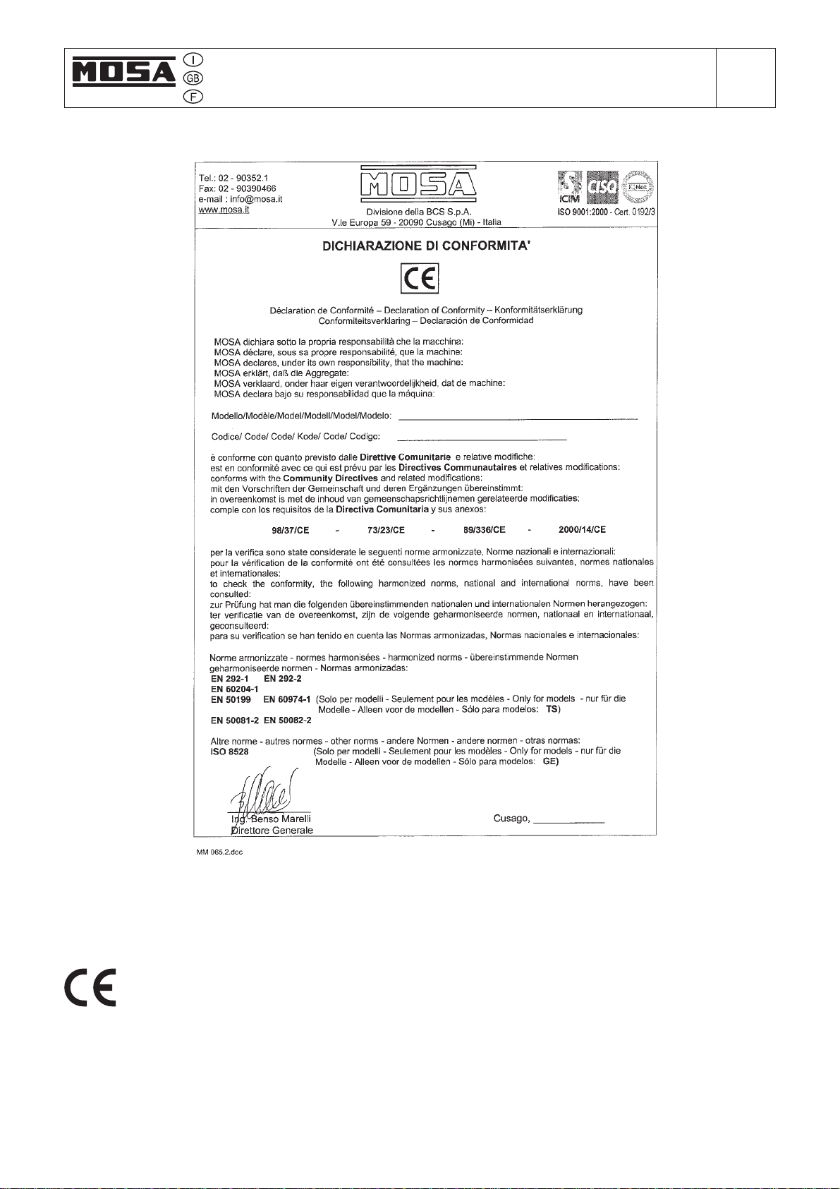
Our products are made in conformity with the
safety norms in force, for which it is advisable to
use all these devices or information so that the
use does not bring damage to persons or things.
While working it is advisable to keep to the
personal safety norms in force in the countries to
whichthe productis destined (clothing,work tools,
etc.).
Donot modify for any motive parts of the machine
(fastenings,holes, electric ormechanicaldevices,
others..)if not dulyauthorized in writing byMOSA:
the responsibility coming from any potential
intervention will fall on the executioner as in fact
he becomes maker of the machine.
Notes GE_, MS_, TS_, EAS_
M
1-1
© MOSA 1.0-10/02
☞Notice: thismanual does not engage MOSA,
who keeps the faculty, apart the essential
characteristicsof the model heredescribed and
illustrated,tobringbettermentsandmodifications
to parts and accessories, without putting this
manualuptodate immediately.
10/10/02 M 1-1 GB

CE MARK GE_, MS_, TS_, EAS_
M
1.4
© MOSA 1.2-06/03
The CE mark (European Community) certifies that the product complies with the essential
safety requirements provided by the applicable COMMUNITY DIRECTIVES. In the Conformity
Declaration are reported the HARMONIZED NORMS and not, used for the checking.
10/10/02 M1-4 GB

SYMBOLS AND SAFETY PRECAUTIONS GE_, MS_, TS_
M
2
© MOSA 1.0-11/99
SYMBOLS IN THIS MANUAL
- The symbols used in this manual are designed to call
your attention to important aspects of the operation of
the machine as well as potential hazards and dangers
forpersons and things.
IMPORTANT ADVICE
- Advice to the User about the safety:
☞N.B.:The information contained in the manual can
bechanged without notice.
Potential damages caused in relation to the use of
these instructions will not be considered because
these are only indicative.
Remember that the non observance of the
indications reported by us might cause damage to
personsor things.
It is understood, that local dispositions and/or laws
must be respected.
WARNING
Situations of danger - no harm to persons
or things
Do not use without protective devices provided
Removing or disabling protective devices on the
machineisprohibited.
Do not use the machine if it is not in good technical
condition
The machine must be in good working order before
being used. Defects, especially those which regard
the safety of the machine, must be repaired before
using the machine.
SAFETY PRECAUTIONS
This heading warns of an immediate danger for persons
as well for things. Not following the advice can result in
seriousinjuryordeath.
This heading warns of situations which could result in
injury for persons or damage to things.
To thisadvicecanappearadangerfor persons aswellas
forthings, for which can appear situations bringing mate-
rial damage to things.
These headings refer to information which will assis you
in the correct use of the machine and/or accessories.
!
ATTENTION
!
NOTE
!
IMPORTANT
!
CAUTION
!
WARNING
!
DANGEROUS
!
26/11/99 M2GB

SYMBOLS AND SAFETY PRECAUTIONS GE_, MS_, TS_
M
2-1
© MOSA 1.1-04/03
SYMBOLS (for all MOSA models)
STOP - Read absolutely and be duly attentive
Readand pay due attention
GENERAL ADVICE - If the advice is not
respected damage can happen to persons or
things.
HIGHVOLTAGE -AttentionHighVoltage.There
can be parts in voltage, dangerous to touch.
The non observance of the advice implies life
danger.
FIRE - Danger of flame or fire. If the advice is
not respected fires can happen.
HEAT - Hot surfaces. If the advice is not
respected burns or damage to things can be
caused.
EXPLOSION - Explosivematerial or danger of
explosion. in general. If the advice is not
respected there can be explosions.
WATER - Danger of shortcircuit. If the advice
is not respected fires or damage to persons
can be caused.
SMOKING - The cigarette can cause fire or
explosion. If the advice is not respected fires
or explosions can be caused.
ACIDS - Danger of corrosion. If the advice is
not respected the acids can cause corrosions
with damage to persons or things.
WRENCH - Use of the tools. If the advice is
notrespected damage can be caused to things
and even to persons.
PRESSION - Danger of burns caused by the
expulsionofhotliquidsunderpressure.
PROHIBITIONS No harm for persons
Use only with safety clothing -
It is compulsory to use the personal
protectionmeans given in equipment.
Use only with safety clothing -
It is compulsory to use the personal protection
means given in equipment.
Use only with safety protections -
Itis a must to use protection means suitable for
thedifferent welding works.
Use with only safety material -
It is prohibited to use water to quench fires on
the electric machines.
Use only with non inserted voltage -
It is prohibited to make interventions before
having disinserted the voltage.
No smoking -
It is prohibited to smoke while filling the tank
with fuel.
No welding -
It is forbidden to weld in rooms containing
explosive gases.
ADVICE No harm for persons and things
Use only with safety tools, adapted to the specific
use -
It is advisable to use tools adapted to the various
maintenanceworks.
Useonly with safety protections, specifically suitable
It is advisable to use protections suitable for
thedifferent welding works.
Use only with safety protections -
It is advisable to use protections suitable
for the different daily checking works.
Use only with safety protections -
It is advisable to use all protections while
shifting the machine.
Use only with safety protections -
It is advisable to use protections suitable for
the different daily checking works.and/or of
maintenance.
!
26/11/99 M2-1GB
ACCESFORBIDDEN tononauthorizadpeaple.

INSTALLATION AND ADVICE BEFORE USE GE_, MS_, TS_
M
2-5
© MOSA 1.0-06/00
Stop engine when fueling
ENGINE
CHECKINGBOARD
Do not touch electric devices if you
are barefoot or with wet clothes.
Always keep off leaning surfaces
during work operations
Static electricity can demage the
parts on the circuit.
An electric shock can kill
The installation and the general advice concerning the operations, are finalized to the correct use of the
machine,intheplacewhere it is used as generator group and/or welder.
!
☞FIRST AID. In case the operator shold be sprayed by accident, from corrosive liquids a/o hot toxic gas
orwhatever event which may cause serious injuries or death, predispose the first aid in accordance with
the ruling labour accident standards or of local instructions.
Skin contact
Eyes contact
Ingestion
Suction of liquids from
lungs
Inhalation
Washwith water and soap
Irrigate with plenty of water, if the irritation persists contact a specialist
Do not induce vomit as to avoid the intake of vomit into the lungs, send for a doctor
If you suppose that vomit has entered the lungs (as in case of spontaneous vomit) take the
subject to the hospital with the utmost urgency
Incase of exposuretohigh concentration of vapourstakeimmediately to anonpolluted zone
theperson involved
☞FIRE PREVENTION. In case the working zone,for whatsoever cause goes on fire with flames liable to
cause severe wounds or death, follow the first aid as described by the ruling norms or local ones.
Appropriated
Not to be used
Otherindications
Particularprotection
Usefulwarnings
Carbonateanhydride (orcarbondioxyde) powder,foam, nebulized water
Avoid the use of water jets
Cover eventual shedding not on fire with foam or sand, use water jets to cool off the
surfaces close to the fire
Wear an autorespiratory mask when heavy smoke is present
Avoid, by appropriate means to have oil sprays over metallic hot surfaces or over electric
contacts (switches,plugs,etc.). In case of oil sprinkling from pressure circuits, keep in
mind that the inflamability point is very low.
EXTINCTION MEANS
WARNING
!
CAUTION
!
!
DANGEROUS
!
WARNING
THE MACHINE MUST NOT BE USED IN AREAS WITH
EXPLOSIVE ATMOSPHERE
10/06/00 M2-5I
Do not smoke, avoid flames, sparks or electric tools when fueling.
Unscrew the cap slowly to let out the fuel vapours.
Slowly unscrew the cooling liquid tap if the liquid must be topped up.
The vapor and the heated cooling liquid under pressure can burn face, eyes, skin.
Do not fill tank completely.
Wipe up spilled fuel before starting engine.
Shut off fuel of tank when moving machine (where it is assembled).
Avoid spilling fuel on hot engine.
Sparks may cause the explosion of battery vapours

INSTALLATION AND ADVICE GE_, MS_, TS_
M
2.6
© MOSA 1.0-11/99
INSTALLATION AND ADVICE BEFORE USE
GASOLINE ENGINES
■Use in open space, air swept or vent exhaust gases,
which contain the deathly carbone oxyde, far from
the work area.
DIESEL ENGINES
■Use in open space, air swept or vent exhaust gases
far from the work area.
POSITION
Place the machine on a level surface at a distance of at
least 1,5 m from buildings or other plants.
Check that the air gets changed completely and the hot
air sent out does not come back inside the set so as to
cause a dangerous increase of the temperature.
☞Make sure that the machine does not move during
the work: block it possibly with tools and/or devices
made to this purpose.
Protect all the electric parts at risk, because water
infiltrations could cause short circuits with damages
at persons and/or things.
The protection degree of the machine is put on the data
plate and in this manual at page "Technical Data".
Maximum leaning of the machine (in case of dislevel)
26/11/99 M2-6GB
1,5 m
1,5 m
1,5 m
GAS DI SCARICO
EXHAUST OUTPUT
MOVES OFTHE MACHINE
☞At any move check that the engine is off, that there
are no connections with cables which impede the
moves.
PLACE OF THE MACHINE
In spots where it often rains and/or there are
flooded areas, do not put the machine:
■
in the bad weather
■
in flooded places.

Installazione
Installation
Installation
Luftzirkulation
Instalación
E
D
NL
GE 225 VPS - VPSX
M
2.7
© MOSA 1.0-07/04
26/07/04 84227-I

UNPACKING GE_, MS_, TS_
M
3
© MOSA 1.1-02/04
NOTE
!
☞Be sure that the lifting devices are: correctly mounted,
adequate for the weight of the machine with it’s
packaging, and conforms to local rules and regula-
tions.
When receiving the goods make sure that the prod-
uct has not suffered damage during the transport,
that there has not been rough handling or taking
away of parts contained inside the packing or in the
set.
In case you find damages, rough handling or ab-
sence of parts (envelopes, manuals, etc.), we ad-
vise you to inform immediately our Technical Ser-
vice.
For eliminating the packing materials, the User
must keep to the norms in force in his country.
1) Take the machine (C) out of the shipment packing.
Take out of the envelope (A) the user’s manual (B).
2) Read: the user’s manual (B), the plates fixed on the
machine, the data plate.
30/03/00 M3GB

TRANSPORT AND DISPLACEMENTS COVERED UNITS AND SKID GE_, MS_, TS_
M
4-2
© MOSA 1.0-03/00
NOTE
!
In case you should transport or move the machine, keep to the instructions as per the figures.
Make the transportation when the machine has no petrol in its tank, no oil in the engine and and electrolyte in the
battery.
Be sure that the lifting devices are: correctly mounted, adequate for the weight of the machine with it’s packaging, and
conform to local rules and regulations.
Only authorized persons involved in the transport of the machine should be in the area of movement.
DO NOT LOAD OTHER PARTS WHICH CAN MODIFY WEIGHT AND BARICENTER POSITION.
IT IS STRICTLY FORBIDDEN TO DRAG THE MACHINE MANUALLY OR TOW IT BY ANY VEHICLE (model with no
CTL accessory).
If you did not keep to the instructions, you could damage the structure of the machine.
30/03/00 M4GB

Set-up for operation TS_,DSP_,GE
Water cooled systems
M
20
© MOSA 1.1-09/05
12/06/03 M20-R-HO2-GB
LUBRICANT
RECOMMENDED OIL
MOSA recommends selecting AGIP engine oil.
Refer to the label on the motor for the recommended
products.
REFUELLING AND CONTROL:
Carry out refuelling and controls with motor at level
position.
1. Remove the oil-fill tap (24)
2. Pour oil and replace the tap
3. Check the oil level using the dipstick (23); the oil
level must be comprised between the minimum
and maximum indicators.
Please refer to the motor operating manual for the
recommended viscosity.
AIR FILTER
Check that the dry air filter is correctly installed and
that there are no leaks around the filter which could
lead to infiltrations of non-filtered air to the inside of
the motor.
It is dangerous to fill the motor with too much oil,
as its combustion can provoke a sudden increase
in rotation speed.
ATTENTION
!
BATTERY WITHOUT MAINTENANCE
Connect the cable + (positive)
to the pole + (positive) of the
battery (after having taken
away the protection), by
properly tightening the clamp.
Check the state of the battery
from the colour of the warning light which is in the
upper part.
- Green colour: battery OK
- Black colour: battery to be recharged
- White colour: battery to be replaced
DO NOT OPEN THE BATTERY.
FUEL
Do not smoke or use open flames during
refuelling operations, in order to avoid
explosions or fire hazards.
Fuel fumes are highly toxic; carry out
operations outdoors only, or in a well-
ventilated environment.
Avoid accidentally spilling fuel. Clean
any eventual leaks before starting up
motor.
ATTENTION
!
Refill the tank with good quality diesel fuel, such as
automobile type diesel fuel, for example.
For further details on the type of diesel fuel to use,
see the motor operating manual supplied.
Do not fill the tank completely; leave a space of
approx. 10 mm between the fuel level and the wall
of the tank to allow for expansion.
In rigid environmental temperature conditions, use
special winterized diesel fuels or specific additives
in order to avoid the formation of paraffin.

Set-up for operation TS_,DSP_,GE
Water cooled systems
M
20.1
© MOSA 1.0-06/03
12/06/03 M20-R-HO2-GB
COOLING LIQUID
Remove the tap and pour the liquid coolant into the
radiator; the quantity and composition of the liquid
coolant are indicated in the motor operating manual.
Replace the tap, ensuring it is perfectly closed.
After refilling operations, allow the motor to run for
a brief time and check the level, as it may have
diminished due to air bubbles present in the cooling
circuit; restore the level with water.
To replace the liquid coolant, follow the operations
described in the motor operating manual.
Do not remove the radiator tap with the
motor in operation or still hot, as the liquid
coolant may spurt out and cause serious
burns. Remove the tap very carefully.
GROUNDING CONNECTION
The grounding connection to an earthed installation
is obligatory for all models equipped with a
differential switch (circuit breaker). In these groups
the generator star point is generally connected to
the machine’s earthing; by employing the TN or TT
distribution system, the differential switch
guarantees protection against indirect contacts.
In the case of powering complex installations
requiring or employing additional electrical protection
devices, the coordination between the protection
devices must be verified.
For the grounding connection, use the terminal
(12); comply to local and/or current regulations in
force for electrical installations and safety.
ATTENTION
!

© MOSA REV.0-07/06
11/07/06 84276-GB
GE 225 VPS - VPSX
GE 275 VPS - VPSX
M
21START AND STOP
NOTE
!
CAUTION
!
MACHINE WITH EMERGENCY BUTTON
Pressing the button the engine will stop
immediately in any working condition.
CAUTION
!
The starting of the unit can be effected in 2 different
modes:
1) Start with EP6 key (Engine Control)
Put the “SWITCH BOARD” selector on ON. Turn
the key on “ON”, the EP6 display shows only on
the machines with mounted glow plugs for 5 secs,
the symbol “UUUU”, then the message “Sta”
appears the engine can be started, for which turn
the key on “start” and start the engine.
On the display the word “Sta” remains for about
20 secs then automatically disappears; the engine
must be started within 20 secs, otherwise the
EP6 blocks the starting and on the display the
word “fail” appears. Turning the key on “OFF” the
EP6 is reset and a new starting cycle can be
fixed.
Stop:
it is COMPULSORY to disconnect the load first,
then to stop the engine turn the key on “OFF”.
2) Remote starting with TCM35
Put the “SWITCH BOARD” selector on ON.
Connect TCM35 to the plug on the front panel
and put the switch on “0”.
Turn the key on ON in the EP6 (Engine Control),
wait for the various signals to go out then press
the button “AUTO” in the EP6 until the led “AUTO”
flashes.
Shift the switch on “I” in the TCM35 and
automatically the starting cycle will start. On the
machines with mounted glow plugs appears in
the display EP6 (for about 5 secs), the symbol
“UUUU“; the starting cycle includes 3 starting
trials.
When the engine starts the led “AUTO” remains
lit continuously and simultaneously the red warning
light will light in the TCM35.
Stop:
it is COMPULSORY to disconnect the load first,
then shift the switch of the TCM35 on “0”, the
engine will stop immediately.
Turn clockwise to reset the button.
For safety reason the key must be kept by
qualified personel.
NOTE
!
Do not alter the primary conditions of regulation
and do not touch the sealed parts.
Check daily
RUNNING-IN
During the first 50 hours of operation, do not use
more than 60% of the maximum output power of
the unit and check the oil level frequently, in any
case please stick to the rules given in the engine
use manual.

Comandi
Controls
Commandes
GE 225 VPS - VPSX
M
31
© MOSA 1.0-05/06
Pos. Descrizione Description Description
X1
C2
D2
H2
Q3
R3
L5
T5
V5
Z5
D6
E6
A7
C7
E7
N7
O7
P7
U7
Presa comando a distanza
Indicatore livello combustibile
Amperometro
Commutatore voltmentrico
Muffola
Avvisatore acustico
Pulsante stop emergenza
Relè differenziale di terra
Indicatore pressione olio
Indicatore temperatura acqua
Connettore PAC
Potenz.regolatore di giri/Freq.
Selettore travaso pompa AUT-0-
MAN
Controllo gruppo elettr. “GECO”
Potenz. regolatore di tensione
Selettore OFF-ON-DIAGN.
Pulsante DIAGNOSTIC
Spia DIAGNOSTIC
Protezione motore EP6
Prise télécommande
lndicateur niveau carburant
Ampéromètre
Commutateur de tension
Planche à bornes prélèv. puissance
Avertisseur sonore
Bouton d’urgence
Relais différentiel de terre
Indicateur pression huile
Indicateur température eau
Connecteur PAC
Potentiomètre régul. de fréquence t/m
Sélecteur transvasement pompe AUT-
0-MAN
Contrôle groupe électrogene "GECO"
Potentiomètre régulateur de tension
Sélecteur OFF-ON DIAGN
Bouton DIAGNOSTIC
Vojant DIAGNOSTIC
Protection moteur EP6
Descripción
Toma mando a distancia
Indicador nivel carburante
Amperímetro de línea
Conmutador voltimétrico
Terminal obtención potencia
Sirena
Pulsador emergencia
Relé diferencial de tierra
Indicador presión aceite
Indicador temperatura agua
Conector PAC
Potenciom.regul. de vueltas/freq.
Selector trasvase bomba AUTO/
0/MAN
Control grupo electrógeno "GECO"
Potenc. regulador de tensión
Selector OFF-ON DIAGN
Pulsador DIAGNOSTIC
Piloto DIAGNOSTIC
Protección motor EP6
E
D
NL
Mandos
22/05/06 84228-I
Remote control socket
Fuel level gauge
Ammeter
Voltage selector switch
Output power unit
Electric siren
Emergency stop button
Earth leakage relay
Oil pressure indicator
Water temperature indicator
Connector, PAC
Frequency rpm regulator
Transfer pump selector AUT-0-
MAN
“GECO” generating set test
Voltmeter regulator
OFF-ON-DIAGN. selector
DIAGNOSTIC push-button
DIAGNOSTIC indicator
Engine protection EP6

USE OF THE GENERATOR GE 225 VPS - VPSX
M
33
© MOSA REV.0-07/06
START AND STOP AUTOMATIC VERSION
Manual start
•Feed the electric board placing the selector SWITCH BOARD
in ON position.
•Choose on te control unit GECO the working mode MAN.
If the control unit GECO is programmed for only manual
start the working modes TEST and AUTOMATIC are
disactivated.
•Start the engine pressing the START key.
•The engine starts at its works speed, check on the control
unit GECO that voltage and frequency values are right.
•After starting let the engine run for a few minutes.
Make sure that there are no danger situations in the plant to
be fed.
•Feed the loads connected placing the power divider POWER
in ON position.
Stop.
At the end of each working set:
•disconnect the loads placing the power divider POWER in
OFF position;
•Let the engine run loadless for e few minutes;
•Press the key STOP on the control unit GECO;
•Cut off feeding the electric board putting the selector
SWITCH BOARD in OFF position.
Automatic start
The generating set associated to the board of only
telecommutation PAC forms a system which supplies electric
energy in few seconds after the commercial mains fails.
Teh control unit GECO provides to substitute failing/presence
of mains and consequently starts or stops automatically the
generating set.
We give here below some general operative information.
•Make safety the connections of the plant.
Position the control unit GECO in RESET.
•Execute the first start in manual mode.
•Position the unit control GECO in AUT mode.
•The generating set is now ready for automatic start.
SIGNALS AND ALARMS
The EDC 4 (Electronic diesel control) is an electronic system
for the gestion of the diesel engines.
The system includes the gestion of the injection and the
diagnosis function.
The information of the sensors placed on the engine supply
the exact grame of the working situation of the engine and
allow tu the central processor to calculate the exact quantity
of fuel to be injected, besides checking the general conditions
of the engine.
The task of the diagnosis function is to identify and signal
possible disfunctions in the EDC 4 system.
The engine protection is entirely secured by the EDC 4
electronic system while the oder devices of the electric board
direct and check the other components of the generating set,
for example: fuel, battery and reloading system, outlet voltage
and frequency, protection against overloads and short
circuits, etc.
Engine alarms
A disfunction noted by the EDC 4 system is signaled by the
diagnosis warning lamp which lights on: the warning lamp
also lights on for 2 seconds during the starting phase to check
how it works.
To find the fault noted by the system proceed in the following
way:
- disconnect the load;
- press for 1-3 seconds the diagnosis push button;
- the diagnosis warning lamp goes out and an instant later a
twinkling series will begin corresponding to e fault code;
-the list of the fault codes and the reading modes of the codes
are to be found in a detailed way in the engine handbook;
- the system might have noted more than one disfunction; it is
necessary to repeat the operation several times, until the
first code does not twinkle again;
- stop the engine and eliminate all the signaled faults;
- Place the selector SWITCH BOARD in DIAGNOSTIC
position, press again the push button to check that there are
no remaining faults, in this case the warning light will twinkle
twice shortly; otherwise it will repeat the code of the fault not
yet repaired.
Some types of alarms consideres as serious by the EDC 4
system cause the engine to stop immediately.
In these cases to find the fault, one must proceed in the
following way:
- place the selector SWITCH BOARD in DIAGNOSTIC
position;
- the diagnosis warning lamps will come on with an
intermittent light;
- press for 1-3 seconds the diagnosis push button and note
the fault code;
- eliminate the fault and make the checking process.
All the passive (repaired) as well as active (to be repaired)
disfunctions are memorized in the system centre and can be
read by means of the equipment Volvo VODIA given to the
authorized Volvo workshops.
ATTENTION
•The selector SWITCH BOARD in DIAGNOSTIC position
impedes the starting of the engine and with running engine
impedes its stop. Use this position only to detect the faults
noted by the EDC 4 engine system.
11/07/06 84228-GB

USE GE 225 - 275 VPS - VPSX
M
33
© MOSA 1.0-09/02
INTRODUCTION
The “GECO” equipment entails a control unit for absolutely
modern generators. Its strong holds are the following:
- Large-size graphical display (95x45 mm) to be able to display
all the electrical parameters at the same time (with characters
of 10mm).
- The membrane keyboard has built-in keys with relative
indicator LEDs. It also offers a high degree of reliability and
ideal touch-sensitive keys.
- The HELP key with relative LED that flashes to point out that
a message is to be read
- The use of the dater clock to set the weekly TEST and to
display all the events that occur and that may be shown on
the Display.
- The control of 4 different mains/generator line systems:
•N-L1-L2-L3
•L1-L2-L3
•L1-N-L2 (AMERICAN market)
•N-L1
- Operational temperature range from -20 to + 60°C
- Protection rating IP64
- 5 possible languages: Italian-English-French-German-
Spanish
- Generator protection against OVERLOADS and SHORT-
CIRCUITS with setting of the rated current of the generator,
setting of the short-circuit current in percentage of the rated
current value of the generator and a tripping delay timing of
the protection device in tenths of a second.
Parameters Displayed
The LCD shows data and information in graphic and
alphanumeric forms. Press the “⇓⇓
⇓⇓
⇓” or “⇑⇑
⇑⇑
⇑” keys to view the data
pages. Press the “–” or “+” keys to see alternative data on the
same page.
N.B. on the display it appears MAINS or GENERATOR for
showing to whom the measure are referred.
The measure on the display are the followings:
-Battery voltage
-Mains and phase generator voltages, between the lines
and of the system
-Phase currents
-Phase and total active, reactive and apparent powers.
-Active, reactive and apparent energy.
-P.F. - Power factor of each phase.
-Energy contact maker
-Frequency of the generator.
-Oil pressure instrument
-Water temperature instrument
-Fuel level instrument
-Engine RPM
-Number of successful starting attempts
-Number of failed starting attempts
-Number of total starting attempts
-Total hours of use
-Partial hours of use
-Hours left to maintenance
KEYBOARD
HELP key – The illuminated LED means a help message is
available. By pressing the key, a help message concerning the
current operation is displayed.
ENTER and EXIT keys - Press ENTER to confirm operations
or to enter the menu. Press EXIT to refuse an operation or to
exit a menu and help message.
“⇓⇓
⇓⇓
⇓” and “⇑⇑
⇑⇑
⇑” arrow keys – Press these keys to shift to the
different pages of data display or to select parameters.
“–” and “+” keys – Press these keys to display alternative
data of the selected data page or to modify the parameters.
OFF/RESET, MAN, AUT and TEST keys – Press these keys
to select the operating mode. The illuminated LED indicates
the selected operating mode; if it is flashing, remote control is
active.
03/09/02 84275-GB

START and STOP keys – These work in MAN operating
mode only, used to start and stop the engine. By quickly
pressing the START key, one start attempt takes place; by
keeping the START key pressed, the duration of the start
attempts can be extended. The flashing LED of the engine
symbol denotes engine started, with alarms inhibited; and is
constantly on at the end of the alarms inhibition time. The
engine can be stopped using the OFF/RESET key.
MAINS and GEN keys – They work in MAN operating mode
only, used to switch the load from mains to generator and vice
versa. The illuminated LEDs of the mains and generator
symbols indicate the respective voltages are within preset
limits. The illuminated LEDs of the changeover symbols indicate
the actual closing of switching devices; when flashing, there is
a incorrect feed-back signal for the actual closing or opening
of the switching devices.
OPERATING MODE
OFF/RESET mode – The engine can not operate. If the mains
is present, the load is switched to the mains. Changing from
TEST, AUT or MAN to the OFF/RESET mode and if the engine
is running, the engine is immediately stopped and eventual
alarms are reset. If the cause of the alarm is still present, it can
not be reset.
MAN mode – The engine can be manually started or stopped
using the START and STOP keys only in addition to load
switching from mains to generator and vice versa, by means of
the MAINS and GEN keys. Always in MAN mode, at the start
command and by keeping the key pressed, the preset starting
time can be prolonged while at the stop command and by
keeping the key pressed for more than 6 seconds, the fuel
valve is discharged for 4 minutes.
AUT mode – In case of mains not present (out of the preset
limits), the engine automatically starts or stops when the
mains returns.
TEST mode – The engine immediately starts even if the
mains is present. In case the mains is not present, the load is
switched to the generator. Changing to the AUT mode and if
the mains is present, the engine will stop.
Alarms
When an alarm arises, the lower section of the display is used
to view it. In case of two alarms or more, they are individually
shown in sequence. A help message is available for every
alarm, in order to locate the possible alarm source. Alarm
conditions can be reset by means of the OFF/RESET key, that
prevent any unintentional engine starting at the alarm reset
operation. If the alarm does not reset, this means the cause of
the alarm is still present. During event-log sessions and set-up
operations, no alarms are viewed.
USE GE 225 - 275 VPS - VPSX
M
33.1
© MOSA 1.0-09/02
03/09/02 84275-GB
This manual suits for next models
3
Table of contents
Popular Industrial Equipment manuals by other brands

Siemens
Siemens SIMATIC S7-4100 Equipment manual

ABB
ABB XAC24851 Operation manual

Siemens
Siemens 3VA9677-0CB10 operating instructions

Reliable
Reliable N2-Blast DDX Instructions for installation, operation care and maintenance

Nexen
Nexen AIR CHAMP TCB-7 user manual

Bornack
Bornack LH200 Translation of the original instructions

Allen-Bradley
Allen-Bradley 198E-AYTJ2 installation instructions

Micromeritics
Micromeritics ACCUPYC II 1345 Series Operator's manual

sauter
sauter EY-RU110 quick reference

Blastrac
Blastrac 1-8DPS30 220V-SP operating instructions

Cassese
Cassese 910 JR owner's manual

HOLZMANN MASCHINEN
HOLZMANN MASCHINEN FS160SOLID operating manual