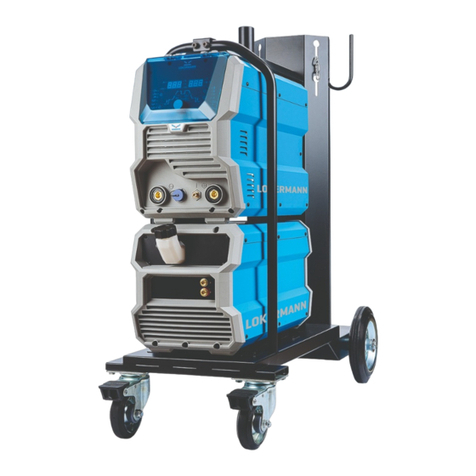
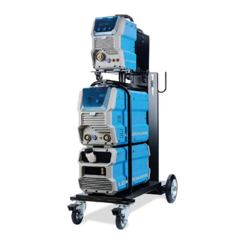
LOKERMANN GRAND MIG 160 User manual

USER MANUAL
INVERTER Based Welding Machines
GRAND
MIG 160
IMPORTANT: Read this OPERATOR MANUAL together
with PRESCRIPTION AND COMPLIANCE MANUAL before
to use this equipment. In case of loss one of two parts
contact immediately your dealer.
Allow the operator to consult this manual.

1INSTALLATION WARNING
2OVERVIEW
2.1 Brief Introduction
2.2 Working Principle
2.3 Volt-Ampere Characteristic
2.4 Principles of welding
3INSTALLATION AND ADJUSTMENT
3.1 Parameters
3.2 Duty cycle and Over-heat
3.3 Equipment Connection
3.4 Maintenance of MIG Gun mechanism
3.5 Maintenance of the wire feed mechanism
4 OPERATION
4.1 Layout for the front and rear panel
4.2 Welding operation
4.2.1 Voltage Setting
4.2.2 Wire speed setting
4.3 Welding trouble shooting
4.3.1 MIG welding trouble shooting
4.3.2 MIG wire feed trouble shooting
4.4 Operation environment
4.5 Operation Notices
5MAINTENANCE & TROUBLESHOOTING
5.1 Maintenance
5.2 Troubleshooting
5.3 List of error code
5.4 Electrical schematic drawing
CONTENT

1
Installation
warning
INSTALLATION WARNING
This machine is certified according to 60974-10:2014 Arc Welding Equipment Part 10: Electromagnetic
compatibility (EMC) requirement and the EUT belongs to Group 2 Class A.
WARNING: This Class A equipment is intended for industrial use and it is not intended for use in
residential locations where the elctrical power is provided by the public low-voltage supply system.
There may be potential difficulties in ensuring electromagnetic compatibility in those locations, due to
conducted as well as radiated disturbances.
WARNING: This equipment does not comply with IEC 61000-3-12. If it is connected to a public low-
voltage system, it is the responsability of the installer or user of the equipment to ensure, by consultation
with the distribution network operator if necessary, that the equipment may be connected.
Assessment of area
Before installing arc welding equipment the user shall make an assessment of potential
electromagnetic problems in the surrounding area. The following shall be taken into account:
a) other supply cables, control cables, signalling and telephone cables, above, below and
adjacent to the arc welding equipment;
b) radio and television transmitters and receivers;
c) computer and other control equipment;
d) safety critical equipment, for example guarding of industrial equipment;
e) the health of the people around, for example the use of pacemakers and hearing aids;
f) equipment used for calibration or measurement;
g) the immunity of other equipment in the environment. The user shall ensure that other
equipment being used in the environment is compatible. This may require additional
protection measures;
h) the time of day that welding or other activities are to be carried out.
The size of the surrounding area to be considered will depend on the structure of the building
and other activities that are taking place. The surrounding area may extend beyond the
boundaries of the premises.
Methods of reducing emissions-Public supply system
Arc welding equipment should be connected to the public supply system according to this manual
recommendations. If interference occurs, it may be necessary to takeadditional precautions such as
filtering of the public supply system. Consideration should be given to shielding the supply cable of
permanently installed arc welding equipment, in metallic conduit or equivalent. Shielding should be
electrically continuous throughout its length. The shielding should be connected to the welding power
source so that good electrical contact is maintained between the conduit and the welding power
source enclosure.
Maintenance of the arc welding equipment
The arc welding equipment should be routinely maintained according to this manual
recommendations. All access and service doors and covers should be closed and properly
fastened when the arc welding equipment is in operation. The arc welding equipment should
not be modified in any way, except for those changes and adjustments covered in this manaul. In
particular, the spark gaps of arc striking and stabilising devices
should be adjusted and maintained according to our recommendations.
Welding cables
The welding cables should be kept as short as possible and should be positioned close
together, running at or close to the floor level.
Equipotential bonding
Bonding of all metallic objects in the surrounding area should be considered. However,
metallic objects bonded to the work piece will increase the risk that the operator could receive
an electric shock by touching these metallic objects and the electrode at the same time. The
operator should be insulated from all such bonded metallic objects.
Earthing of the workpiece
Where the workpiece is not bonded to earth for electrical safety, nor connected to earth
because of its size and position, for example, ship’s hull or building steelwork, a connection
bonding the workpiece to earth may reduce emissions in some, but not all instances. Care should be
taken to prevent the earthing of the workpiece increasing the risk of injury to users or damage to other
electrical equipment. Where necessary, the connection of the workpiece to earth should be made by
a direct connection to the workpiece, but in some countries where direct connection is not permitted,
the bonding should be achieved by suitable capacitance, selected according to national regulations.
Screening and shielding
Selective screening and shielding of other cables and equipment in the surrounding area may
alleviate problems of interference. Screening of the entire welding area may be considered for
special applications.
2
Overview
2.1
Brief
Introduction
GRAND MIG 160 adopts the latest Pulse Width Modulation (PWM) technology and the Insulated Gate
Bipolar Transistor (IGBT) power modules. It uses switching frequencies in the 20KHz-50KHz range so as
to replace the traditional line-frequency transformer type welding machines. Thus, machines are
characterized with excellent dynamic response, portability, small size, lightweight, low energy
consumption, etc.
GRAND MIG 160 uses Mix gases as shielding gas to realize gas shielded welding, active gas
(Ar+O2、Ar+CO2)as shielded gas to realize MAG welding and inactive gas(Ar)as shielded gas to
realize MIG welding.
GRAND MIG 160 has built-in automatic protection functions to protect the machines from
over-voltage, over-current and over-heat. If any one of the above problems happens, the alarm
lamp on the front panel will be lit and output current will be shut off automatically for the machine to
protect itself and prolong the equipment using life.
GRAND MIG 160 Features:
1. Digital control system, real-time display the welding parameters;
2. High performance multifunction power source (MIG/MAG);
3. Waveform control, stable welding arc;
4. IGBT technology, low power consumption;
5. Rated Duty Cycle:
GRAND MIG 160 = 160A @ 25%(40°C)
GRAND MIG 160 is suitable for all positions welding for various plates made of stainless steel, carbon
steel,alloyed steel etc. Applications applied to pipe installment, petrochemical, architecture
equipment, car repair, bicycle repair, handicraft and common steel fabrication.
MAG--Metal Active Gas Welding
MIG--Metal Insert Gas Welding
2.2
Working
Principle The working principle of MIG series arc welding machine is shown as the following figure.
Single-phase 220V work frequency AC is rectified into DC�312V�, then is converted to medium
frequency AC (about 50KHz) by inverter device (IGBT), after reducing voltage by medium
transformer (the main transformer) and rectifying by medium frequency rectifier (fast recovery
diodes), and is outputted by inductance filtering. When MIG. Meanwhile, the welding current
parameter can be adjusted continuously and infinitely to meet with the requirements of welding craft.
single-phase AC
220V 50/60 HZ

2.3
Volt-Ampere
Characteristic MIG series welding machine has an excellent volt-ampere characteristic, whose graph is shown as the
following figure. The relation between the rated loading voltage U2 and welding current I2
is as follows: U2=14+0.05I2 (V)
44
14
0 600 I
o
(A)
U
o
(V)
Working point
Volt-ampere characteristic The relation between the rated loading
voltage and welding current
2.4
Principles
of welding
3
Installation
and
Adjustment
3.1
Parameters
Models
Parameters
GRAND MIG 160
Input Voltage(V)1~220/230/240±10%
Input Current (I1max)(A)31
Input Power(KW)4.6
Welding Current(A)40-160
Welding Voltage Range (V) 16-22
No-load Voltage(V)70
Duty cycle(40℃)
25% 160A
60% 105A
100% 80A
Diameter(mm)
0.6、0.8、0.9
(Fe /Ss/Flux-Cored)
Protection class
IP23
Insulation class
H
Dimensions
(
mm
)
600*240*425
Weight
(
Kg
)
16
Note: The above parameters are subject to change with future machine improvement!

3.2
Duty cycle
and
Over-heat
The letter “X” stands for Duty Cycle, which is defined as the portion of the time a welding machine
can weld continuously with it’s rated output current within a certain time cycle (10 minutes).
The relation between the duty cycle “X” and the output welding current “I” is shown as the right figure.
If the welding machine is overheating, the IGBT over-heat protection sensing will send a signal to the
welding machine control unit to cut the output welding current OFF and light the over-heat pilot lamp
on the front panel. In that case, the machine should not be welding for 10-15 minutes to cool down
with the fanrunning. When operating the machine again, the welding output current or the duty
cycle should be reduced.
3.3
Equipment
Connection
(1) Insert the earth cable plug into the negative socket on the front of the machine and tighten it.
(2) Plug the welding torch into the MIG torch connection socket on the front panel and tighten it.
IMPORTANT : When connecting the torch be sure to tighten the connection. A loose connection
can result in the connector arcing and damaging the machine and gun connector.
(3) Connect the gas regulator to the Gas Cylinder and connect the gas line to the Gas Regulator.
Check for Leaks!
(4) Connect the gas line to gas connector on the rear panel. Check for Leaks!
(5) Connect the power cable of welding machine with the output switch in electric box on site.
(6) Place the Wire Spool onto the Spool Holder. Snip the wire from the spool being sure to hold the
wire to prevent rapid uncoiling. Feed the wire into the wire feeder inlet guide tube through to the
drive roller.
(7) Carefully feed the wire over the drive roller into the outlet guide tube, feed through about 150mm
into the torch receptacle. Check that the drive roller size is compatible with the wire diameter,
replace the roller if necessary.
(8) Align the wire into the groove of the drive roller and close down the top roller making sure the wire
is in the groove of the bottom drive roller, lock the pressure arm into place. Apply a medium
amount of pressure to the drive roller.

3.4
Maintenance
of MIG Gun
mechanism
1. Service the wire feed mechanism at least every time the reel is changed.
· Check the wear of the feed roll groove and change the feed roll when necessary.
· Clean the welding gun wire guide with compressed air.
2. Cleaning the wire guide
Pressure of the feed rolls remove metal dust from the filler wire’s surface which then finds its way to the
wire guide. If the wire guide is not cleaned, it gradually clogs up and causes wire feed malfunctions.
Clean the wire guide in the following manner:
Remove the welding gun’s gas nozzle, contact tip and contact tip’s adapter.
With a pneumatic pistol, below compressed air through the wire guide.
Blow the wire feed mechanism and reel housing clean with compressed air.
Reattach the welding gun’s parts. Tighten the contact tip and contact tip’s adapter to spanner
tightness.
3. Changing the wire guide
If the wire guide is too worn or totally clogged, change it to a new one according to the following
instructions.
Open the mounting nut of the wire guide which exposes the end of the wire guide.
Straighten the welding gun’s cable and withdraw the wire guide from the gun.
Push a new wire guide in to the gun. Make sure that the wire guide enters all the way into the contact
tip’s adapter and that there is an O-ring at the machine-end of the guide.
Tighten the wire guide in place with the mounting nut.
Cut the wire guide 2mm from the mounting nut and file the sharp edges of the cut round.
Reattach the gun in place and tighten the parts to spanner tightness.
3.5
Maintenance
of the wire
feed
mechanism
Changing the feed roll groove
The feed roller is factory set for welding filler wires of 0.6-0.8mm V shape. The feed roller side must be
changed if you use 0.6mm thick filler wire.
Threading the filler wire
Threading the filler wire as the follow steps:
Open the reel housing by pressing on the opening button and install the wire reel in such a way that it
rotates counter clockwise. You can use a diameter 200mm wire reel in the machine.
Attach the reel with a reel lock.
Unfasten the wire end from the reel, but hold on it all the time.
Straighten the wire end for approximately 20 cm and cut the wire in the straightened location.
Open the pressure control level which then opens the feed gear.
Thread the wire through the wire’s rear guide to the gun’s wire guide.
Close the feed gear and fasten it with the pressure control lever. Make sure that the wire runs in the
feed roll groove.

4
Operation
4.1
Layout for
the front and
rear panel
1. Output “-“
2. MIG GUN Connect.
3. Welding current/wire speed knob: Set the welding current/wire speed.
4. Welding volt knob: Set the welding volt
5. Alarm Led: When the welder is over voltage, less voltage, over current or over heated, the alarm
pilot lamp will be on.
6. Voltage display: Welding voltage display when machine is working, Set voltage display when MIG
mode before welding. Unit:V.
7. Power Led: Power led is lighted when switch on the machine.
8. Current display: Welding Current display when machine is working, Set current display before
welding. Unit:A.
9. Wire speed LED: You can use current setting knob to set the wire speed when the wire speed
LED is on.
10. Choose welding mode button: Pressing the button can choose 2T or 4T welding mode.
11. 2T welding mode LED: When the 2T welding mode LED is on , it can 2T welding mode,2T is suitable
for the short welding.
12. 4T welding mode LED: When the 4T welding mode LED is on , it can 4T welding mode, 4T is suitable
for the long welding.
13. Wave control knob: Controls arc characteristics, Determines the rate at which the amperage
rises when a short circuit is produced, decreasing the spatters.
14. Current LED: When the current LED is on, it display the actual output welding current.
15. Power source input: To connect power source.
16. On/off switch: Control the power supply on and off.
17. Shield gas input joint: To connect one head of the gas hose while the other head of which is
connected to the gas cylinder.
18. Inside the wire feeder compartment there is the BBT knob (burn back time).
19. Inside the wire feeder compartment the is the possibility to inverse the polarity in order to weld flux
wires that required it.

4.2 Welding
operation
4.2.1 Voltage
setting
You can use the voltage setting knob to set the output voltage before welding.
4.2.2 Wire
speed setting
You can use current setting knob to set the wire speed when the wire speed LED is on. When the
current LED is on, it display the actual output welding current.
4.3
Welding trouble
shooting
4.3.1
MIG welding
trouble
shooting
The following chart addresses some of the common problems of MIG welding. In all cases of
equipment malfunction, the manufacturer’s recommendations should be strictly adhered to and
followed.
NO. Trouble Possible Reason Suggested Remedy
1
Excessive
Spatter
Wire feed speed set too high Select lower wire feed speed
Voltage too high
Select a lower voltage setting
Wrong polarity set
select the correct polarity for the
wire being used - see machine
setup guide
Stick out too long
Bring the torch closer to the work
Contaminated base metal
Remove materials like paint,
grease, oil, and dirt, including
mill scale from base metal
Contaminated mig wire
Use clean dry rust free wire. Do
not lubricate the wire with oil,
grease etc
Inadequate gas flow or too much
gas flow
Check the gas is connected, check
hoses, gas valve and torch are not
restricted. Set the gas flow
between 6-12 l/min flow rate.
Check hoses and fittings for
holes, leaks Protect the welding
zone from wind and drafts
2
Porosity - small
cavities or holes
resulting from
gas pockets in
weld metal.
Wrong gas
Check that the correct gas is
being used
Inadequate gas flow or too much
gas flow
Check the gas is connected, check
hoses, gas valve and torch are not
restricted. Set the gas flow
between 10 - 15 l/min flow rate.
Check hoses and fittings for
holes, leaks etc .Protect the
welding zone from wind and
drafts
Moisture on the base metal
Remove all moisture from base
metal before welding
Contaminated base metal
Remove materials like paint,
grease, oil, and dirt, including
mill scale from base metal
Contaminated mig wire
Use clean dry rust free wire. Do
not lubricate the wire with oil,
grease etc
Gas nozzle clogged with spatter,
worn or out of shape
Clean or replace the gas nozzle
Missing or damaged gas diffuser
Replace the gas diffuser
Mig torch euro connect o-ring
missing or damaged
Check and replace the o-ring
3 Wire stubbing
during welding
Holding the torch too far away
Bring the torch closer to the work
and maintain stick out of 5-10mm
Welding voltage set too low
Increase the voltage
Wire Speed set too high
Decrease the wire feed speed
4
Lack of Fusion −
failure of weld
metal to fuse
completely with
base metal or a
proceeding weld
bead.
Contaminated base metal
Remove materials like paint,
grease, oil, and dirt, including
mill scale from base metal
Not enough heat input
Select a higher voltage range and
/or adjust the wire speed to suit
Improper welding technique
Keep the arc at the leading edge
of the weld pool.
Gun angle to work should be
between 5 & 15° Direct the arc at
the weld joint
Adjust work angle or widen
groove to access bottom during
welding
Momentarily hold arc on side
walls if using weaving technique
5
Excessive
Penetration −
weld metal
melting through
base metal
Too much heat
Select a lower voltage range and
/or adjust the wire speed to suit
Increase travel speed

4.3.2
MIG wire
feed trouble
shooting
The following chart addresses some of the common WIRE FEED problems during MIG welding. In all
cases of equipment malfunction, the manufacturer’s recommendations should be strictly adhered
to and followed.
Possible Reason
Suggested Remedy
Wrong polarity selected
Select the correct polarity for the wire being
used - see machine setup guide
Incorrect wire speed setting
Adjust the wire feed speed
Voltage setting incorrect
Adjust the voltage setting
Mig torch lead too long
Small diameter wires and soft wires like
aluminium don’t feed well through long torch
leads - replace the torch with a lesser length
torch
Mig torch lead kinked or too
sharp angle being held
Remove the kink, reduce the angle or bend
Contact tip worn, wrong
size, wrong type
Replace the tip with correct size and type
Liner worn or clogged (the
most common causes of bad
feeding)
Try to clear the liner by blowing out with
compressed air as a temporary cure, it is
recommended to replace the liner
Wrong size liner
Install the correct size liner
Blocked or worn inlet guide
tube
Clear or replace the inlet guide tube
Wire misaligned in drive
roller groove
Locate the wire into the groove of the drive
roller
Incorrect drive roller size
Fit the correct size drive roller eg; 0.8mm wire
requires 0.8mm drive roller
Wrong type of drive roller
selected
Fit the correct type roller (e.g. knurled rollers
needed for flux cored wires
Worn drive rollers
Replace the drive rollers
Drive roller pressure too
high
Can flatten the wire electrode causing it to
lodge in the contact tip - reduce the drive roller
pressure
Too much tension on wire
spool hub
Reduce the spool hub brake tension
Wire crossed over on the
spool or tangled
Remove the spool untangle the wire or replace
the wire
Contaminated mig wire
Use clean dry rust free wire. Do not lubricate
the wire with oil, grease etc
4.4
Operation
environment
▲ Height above sea level ≤1000 M
▲ Operation temperature range -10〜+40°C
▲ Air relative humidity is below 90 %( 20°C)
▲ Preferable site the machine some angles above the floor level, the maximum angle does not
exceed 15℃.
▲ Protect the machine against heavy rain AND against direct sunshine.
▲ The content of dust, acid, corrosive gas in the surrounding air or substance cannot exceed normal
standard.
▲ Take care that there is sufficient ventilation during welding. There must be at least 30cm free
distance between the machine and wall.
6
Lack of
Penetration −
shallow fusion
between weld
metal and base
metal
Poor in incorrect joint preparation
Material too thick. Joint
preparation and design needs to
allow access to bottom of groove
while maintaining proper welding
wire extension and arc
characteristics Keep the arc at the
leading edge of the weld pool and
maintain the gun angle at 5 & 15°
keeping the stick out between 5-
10mm
Not enough heat input
Select a higher voltage range and
/or adjust the wire speed to suit
Reduce travel speed
Contaminated base metal
Remove materials like paint,
grease, oil, and dirt, including
mill scale from base metal

4.5
Operation
Notices ▲ Read Section §1 carefully before starting to use this equipment.
▲ Ensure that the input is single-phase: 50/60Hz, 220V ±15%.
▲ Before operation, none concerned people should not be around the working area and especially
children. Do not watch the arc in unprotected eyes.
▲ Ensure good ventilation of the machine to improve Duty Cycle.
▲ Turn off the engine when the operation finished for energy consumption efficiency.
▲ When power switch shuts off protectively because of failure. Don’t restart it until problem is resolved.
Otherwise, the range of problem will be extended.
▲ In case of problems, contact your local dealer if no authorized maintenance staff is available!
5
Maintenance
&
Troublesho-
oting
5.1
Maintenance
In order to guarantee that arc welding machine works high properly, it must be maintained regularly. Let
customers understand the maintenance methods. Enable customers to carry on simple maintenance by
themselves. Try one's best to reduce the fault rate and repair times of arc welding machine, so as to
lengthen service life of arc welding machine. Maintenance items in detail are in the following table.
● Warning: For safety while maintaining the machine, please shut off the main input power and wait for 5
minutes, until capacitors voltage already drop to safe voltage 36V!
Date
Maintenance items
Daily
examinati
on
Observe that the knobs and switches in the front and at the back of arc
welding machine are flexible and put correctly in place. If any knob has not
been put correctly in place, please correct. If you can't correct or fix the knob,
please replace immediately;
If any switch is not flexible or it can't be put correctly in place, please replace
immediately. Please get in touch with maintenance service department if there
are no accessories.
After turn-on power, watch/listen if the arc-welding machine has shaking,
whistle calling or peculiar smell. If there is one of the above problems, find out
the reason and clear it. If you can't find out the reason, please contact your local
service repair station or distributor/agent .
Observe that the display value of LED is intact. If the display number is not
intact, please replace the damaged LED. If it still doesn’t work, please maintain
or replace the display PCB.
Observe that the min/max values on LED agree with the set value. If there is
any difference and it has affected the normal welding results, please adjust it.
Check whether the fan is damaged and whether it is normal to rotate or
control. If the fan is damaged, please change immediately. If the fan does not
rotate after the machine is overheated, observe if there is something blocking
the blade. If it is blocked, please clear the problem. If the fan does not rotate
after getting rid of the above problems, you can poke the blade by the rotation
direction of fan. If the fan rotates normally, the start capacity should be
replaced. If not, change the fan.
Observe whether the fast connector is loose or overheated. If the arc- welding
machine has the above problems, it should be fastened or changed.
Observe whether the current output cable is damaged. If it is damaged, it
should be insulated or changed.
Monthly
examinati
on
Using the dry compressed air to clear the inside of arc welding machine.
Especially for clearing up the dusts on radiator, main voltage transformer,
inductors, IGBT modules, fast recover diodes, PCB’s, etc.
Check the screws and bolts in the machine. If any is loose, please screw it
tight. If it is shaved, please replace. If it is rusty, please erase rust on all bolts to
ensure it works well.
Quarter-
yearly
examinati
on
Check whether the actual current accords with the displaying value. If they did
not accord, they should be regulated. The actual welding current value can be
measured by and adjusted by plier-type ampere meter.
Yearly
examinati
on
Measure the insulating impedance among the main circuit, PCB and case, if it
below 1MΩ, insulation is thought to be damaged and need to change, and need
to change or strengthen insulation.

5.2
Troublesho-
oting - Before the welding machines are dispatched from the factory, they have already been tested and
calibrated accurately. It is forbidden for anyone who is not authorized by our company to do any
change to the equipment!
- Maintenance course must be operated carefully. If any wire becomes flexible or is misplaced, it
maybe potential danger to user!
- Only professional maintenance staff that isauthorized by our company could overhaul the machine!
- Be sure to shut off the Main Input Power before doing any repair work on the welding machine!
- If there is any problem and there is no authorized professional maintenance personal on site,
please contact local agent or the distributor!
If there are some simple troubles with the welding machine, you can consult the following Chart:
:
NO. Troubles Reasons Solution
1 Close the breaker, but the
power light isn’t on
Breaker damaged Change it
Fuse damaged Change it
Power damaged Change it
2
After welding machine is
over-heat, the fan doesn ’t
work
Fan damaged Change it
The cable is loosen Screw the cable tightly
3
Press the
gun switch,
no output
shielded gas
No output gas
when test gas
No gas in the gas cylinder Change it
Gas pipe leaks gas Change it
Electromagnetic valve
damaged
Change it
Output gas
when test gas
Control switch damaged Repair the switch
Control circuit damaged Check the board
4
Wire-feeder
doesn’t
work
Wire reel
doesn’t work
Motor damaged Check and change it
Control circuit damaged Check the board
Wire reel
works
The press wheel is loosen or
weld wire skids
Press it tightly again
The wheel doesn ’t fit with
the diameter of weld wire
Change the wheel
Wire reel damaged Change it
Wire feed pipe is jammed Repair or change it
Tip is jammed because of
splash
Repair or change it
5 No striking arc and no output
voltage
Output cable is connected
mistakenly, or loosen
Screw it down or change it
Control circuit damaged Check the circuit
6 Welding stops, and alarm
light is on Machine has self-protection
Check ove r-voltage, over -current, over -
temperature, lower -voltage and over -
temperature, and solve it
7 Welding current is run away
and can be not controlled
The potentiometer damaged Check or change it
The control circuit
damaged
Check the circuit
8
The crater current can be not
adjusted
The PCB damaged Check it
9 No post-gas The PCB damaged Check it
Error Type Error code Description Lamp status
Thermal relay
E01 Over-heating(1st thermal relay)
Yellow lamp(thermal
protection) always on
E02 Over-heating(2nd thermal relay)
Yellow lamp(thermal
protection) always on
E03 Over-heating(3rd thermal relay)
Yellow lamp(thermal
protection) always on
E04 Over-heating(4th thermal relay)
Yellow lamp(thermal
protection) always on
E09 Over-heating(Program in default)
Yellow lamp(thermal
protection) always on
Welding
machine
E10 Phase loss
Yellow lamp(thermal
protection) always on
E13 Under voltage
Yellow lamp(thermal
protection) always on
E14 Over voltage
Yellow lamp(thermal
protection) always on
E15 Over current
Yellow lamp(thermal
protection) always on
E16
Wire feeder over load
Switch
E20
Button fault on operating panel
when switch on the machine
Yellow lamp(thermal
protection) always on
E21
Other faults on operating panel
when switch on the machine
Yellow lamp(thermal
protection) always on
E41
Communication error
5.3
List of error
code

5.4
Electrical
schematic
drawing

L
OKERMANN Srl,
V
ia Produzione 16/18, 37044, Cologna Veneta,
(
VR)
-
Italy, Tel: +39 0442 1722469
l
okermann@lokermann.eu
-www.lokermann.eu
Table of contents
Other LOKERMANN Welding System manuals

LOKERMANN
LOKERMANN GRAND TIG 250 DC PULSE User manual

LOKERMANN
LOKERMANN GRAND ARC 400 CEL User manual

LOKERMANN
LOKERMANN GRAND TIG 200 DC User manual

LOKERMANN
LOKERMANN GRAND TIG 200 DC PFC MV User manual

LOKERMANN
LOKERMANN GRAND MIG 400 PULSE User manual

LOKERMANN
LOKERMANN GRAND PIPE 270 MULTI User manual

LOKERMANN
LOKERMANN GRAND MIG 200 MULTI PFC SYN MV User manual

LOKERMANN
LOKERMANN GRAND CUT 41 COM User manual

LOKERMANN
LOKERMANN GRAND CUT 60 User manual

LOKERMANN
LOKERMANN GRAND AIR HD User manual