Mostec M4036 User manual

M4036OM V1.11e/20.09.2023
Operating manual
Conductivity meter
Type M4036

Operating instruction manual M4036
Chapter: Revision
Page 2
Revision
Version Date Changes
V1.10 05.09.2023 Valid for M4036 as of firmware version 1.00.18

Operating instruction manual M4036
Chapter: Content
Page 3
Content
Revision .................................................................................................................................................................................... 2
Content ..................................................................................................................................................................................... 3
Operating notes ........................................................................................................................................................................ 4
Warranty ...................................................................................................................................................................................... 4
Technical description ................................................................................................................................................................... 4
Technical support ........................................................................................................................................................................ 4
Contact details ....................................................................................................................................................................... 4
Safety instructions ....................................................................................................................................................................... 5
Operating regulations .................................................................................................................................................................. 5
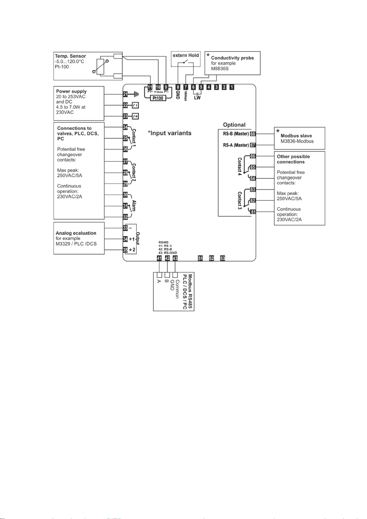
Wiring diagram ............................................................................................................................................................................ 6
Connections ................................................................................................................................................................................. 7
Additional clamp (optional) ................................................................................................................................................... 7
Instrument overview ................................................................................................................................................................ 8
Instrument elements ................................................................................................................................................................... 8
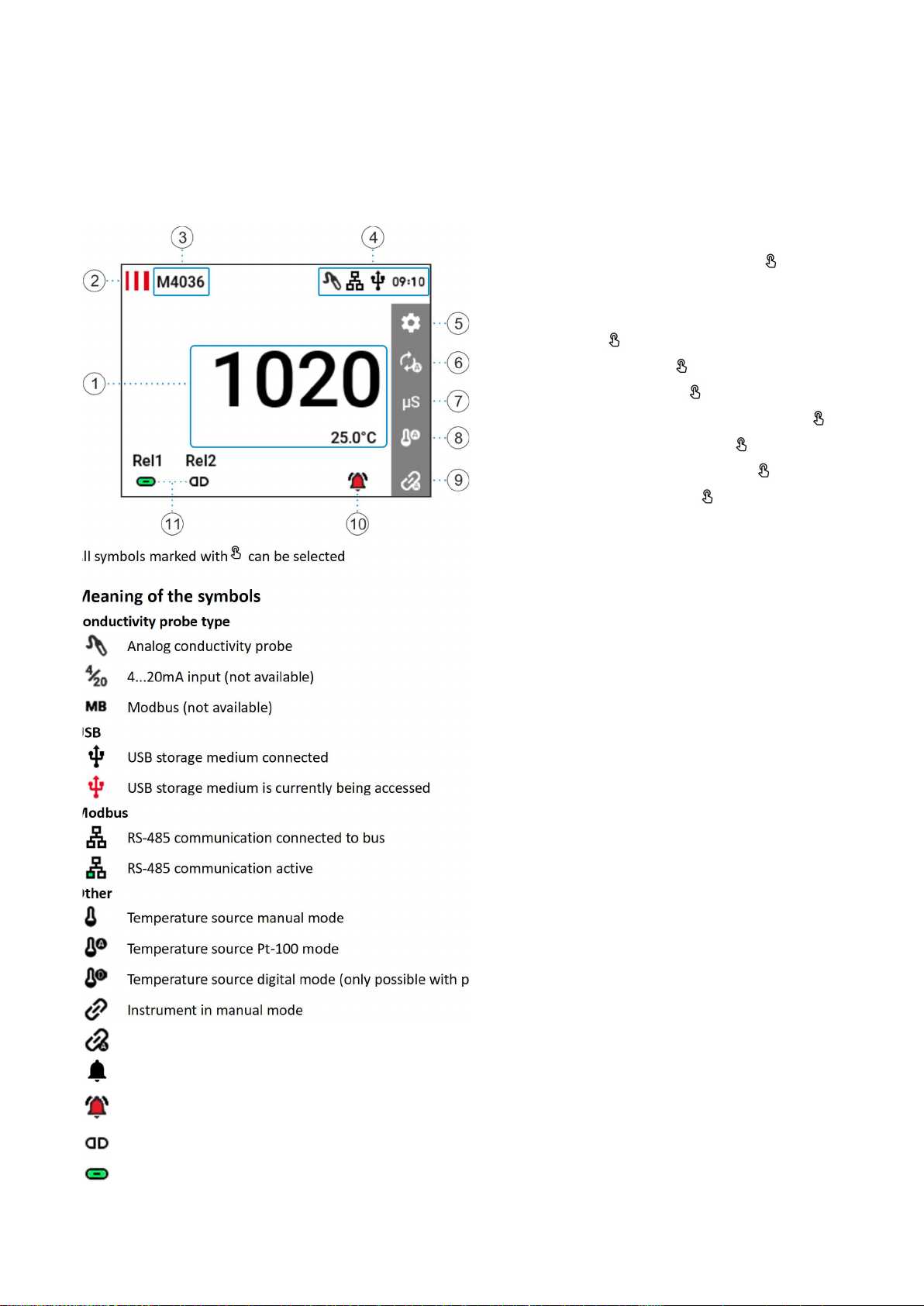
Measurement screen ............................................................................................................................................................. 8
Meaning of the symbols ........................................................................................................................................................ 8
User menu ................................................................................................................................................................................ 9
Settings ........................................................................................................................................................................................ 9
Measurement settings ............................................................................................................................................................... 10
Signal output 1 & 2 settings ................................................................................................................................................. 11
Temperature settings ........................................................................................................................................................... 11
Device settings ........................................................................................................................................................................... 12
Limit settings ............................................................................................................................................................................. 12
Limit contact 1 & 2 settings ................................................................................................................................................. 13
Alarm settings ...................................................................................................................................................................... 14
Alarm SP1 & SP2 settings ..................................................................................................................................................... 14
USB settings ............................................................................................................................................................................... 15
Modbus settings ........................................................................................................................................................................ 15
Devices Info ............................................................................................................................................................................... 15
Operation of the device .......................................................................................................................................................... 16
Alarm Log ................................................................................................................................................................................... 16
Explanation of the Alarm Log Symbols ................................................................................................................................ 16
USB Logger ................................................................................................................................................................................ 17
Features of the USB Logger .................................................................................................................................................. 17
File name / file format ......................................................................................................................................................... 17
Example................................................................................................................................................................................ 17
Saving and restoring the device settings ................................................................................................................................... 17
Firmware update ....................................................................................................................................................................... 17
Appendix ................................................................................................................................................................................ 18
Dimensions ................................................................................................................................................................................ 18
Side view: ............................................................................................................................................................................. 18
Rear view: ............................................................................................................................................................................ 18
Technical data ............................................................................................................................................................................ 19

Operating instruction manual M4036
Chapter: Operating notes
Page 4
Operating notes
Warranty
Mostec AG grants a warranty of 2 years on the measuring device mentioned. The period for calculating the warranty period
begins with the invoice date. During the warranty period, defects which are not due to improper use will be repaired free of
charge. Excluded are damages caused by use, for example such as scratched front panels and displays, corroded
potentiometers, entry of water or similar defects.
There is an extended warranty of additional 2 years on long term damages, should they be due to faulty manufacturing. This
includes bad and cold solder joints, as well as assembly errors, which only become noticeable after a longer period of
operation.
The warranty repair must in any case be carried out at Mostec. Postage and packaging expenses shall be paid by the customer.
In the event of a warranty claim, the repaired unit will be returned at Mostec's expense. Transport damages are excluded from
any warranty service and must be reported to the delivering carrier.
Technical description
The very compact conductivity meter type M4036 was developed for applications for automatic dosing or monitoring purposes.
A bright and sunlight readable 3.5 inch IPS display allows reading of the measured value even in bright environments. The touch
screen can be operated smoothly and enables intuitive and uncomplicated use.
The two-point controller consists of two potential-free limit contacts which can be electronically adjusted over the entire range.
In order to control alarm devices, dosing valves and dosing pumps, among other things, these limit contacts can be used. The
current measured value, the temperature, as well as the device status are continuously displayed.
A galvanically isolated wide range power supply from 20 to 253VAC/DC supplies the device and only a conductivity electrode is
needed for the instrument to be ready for operation. Commercially available probes with K-factors 0.01, 0.1, 1.0 and 10.0 cover
a dynamic range from 1µS to 200mS (example: M8836S). The cable length of the probe is internally automatically compensated
has no influence on the measurement.
Temperature compensation is done either manually or with an external Pt-100 sensor. Defects of the Pt-100 sensor are
immediately indicated and trigger an alarm. The conditions for such an alarm trigger can be defined. All device settings can be
protected by means of an access code.
A USB stick can be used to automatically log the measured values. Two programmable, galvanically isolated signal outputs are
available to send for example the measurement value and the temperature to a PLC.
Technical support
For questions or concerns, we can be reached by email or phone.
Current operating instructions can be found on our website www.mostec.swiss.
Contact details
Mostec AG
Lausenerstrasse 13a
CH-4410 Liestal BL
Phone: +41 61 921 40 90
E-mail: info@mostec.ch

Operating instruction manual M4036
Chapter: Operating notes
Page 5
Safety instructions
Observe the customary national regulations and safety requirements for electrical, light and heavy current
installations.
Read and observe the safety regulations of these operating instructions before using the device.
The device must be mounted in such a way that it is protected from moisture, vibrations and heavy soiling.
When working on the control panel, all lines leading to the device must be de-energized if there is a risk that the
terminals located on the device could be touched.
The limit values for the variables specified in the data sheet must not be exceeded under any circumstances.
Wiring, commissioning and operation of the equipment must be carried out by suitably qualified personnel in
accordance with local regulations.
If it can be assumed that the device can no longer be operated without danger, it must be taken out of service and
secured against further operation by labeling.
Failure to follow the safety instructions may result in damage to the device and injury to the operator.
Operating regulations
1. Connect the device according to the wiring diagram.
2. After all necessary connections have been made, the supply voltage of the system can be switched on.
3. Make the appropriate settings for the respective operation.

Operating instruction manual M4036
Chapter: Operating notes
Page 6
Wiring diagram

Operating instruction manual M4036
Chapter: Operating notes
Page 7
Connections
5 Probe + input 6 Probe - input 7 Hold input 8 GND
9 Pt-100 probe (-) 10 Pt-100 probe sense(-) 11 Pt-100 probe (+)
21 Protective earth PE 22 Supply power (-) 23 Supply power (+)
24 Limit value 1: normally
open contact (NO) 25 Limit value 1:
changeover contact 26 Limit value 1: normally
closed contact (NC)
27 Limit value 2: normally
open contact (NO) 28 Limit value 2:
changeover contact 29 Limit value 2: normally
closed contact (NC)
30
Alarm contact:
normally open contact
(NO)
31
Alarm contact:
changeover contact 32
Alarm contact:
normally closed contact
(NC)
33 Signal output GND 34 Signal output 1 35 Signal output 2
41 Modbus RS485-A 42 Modbus RS485-B 43 Modbus RS485-GND
Additional clamp (optional)
61 Limit value 3: normally
open contact (NO) 62 Limit value 3: normally
closed contact (NC) 63 Limit value 3:
Changeover contact
64 Limit value 4: normally
open contact (NO) 65 Limit value 4: normally
closed contact (NC) 66 Limit value 4:
Changeover contact
67 Modbus RS485 Master-
A 68 Modbus RS485 Master-
B

Operating instruction manual M4036
Chapter: Instrument overview
Page 8
Instrument overview
Instrument elements
Measurement screen
1. Current measured values
2. Logo and "Device info" entry
3. Device label
4. Status bar with current time
5. Settings
6. Measuring range
7. Measurement unit
8. Temperature measurement source
9. Auto / manual operation
10. Alarm display and alarm log
11. Status limit contacts
All symbols marked with can be selected
Meaning of the symbols
Conductivity probe type
Analog conductivity probe
4...20mA input (not available)
Modbus (not available)
USB
USB storage medium connected
USB storage medium is currently being accessed
Modbus
RS-485 communication connected to bus
RS-485 communication active
Other
Temperature source manual mode
Temperature source Pt-100 mode
Temperature source digital mode (only possible with probe type Modbus)
Instrument in manual mode
Instrument in automatic mode
No alarm active
Alarm active (flashing symbol)
Alarm acknowledged (steady symbol)
Switching contact open
Switching contact closed

Operating instruction manual M4036
Chapter: User menu
Page 9
User menu
The user menu has the following submenus. In these submenus, device-specific settings can be made.
The bar on the right side is a scroll bar
The default values are shown [Bold]
Settings
Enter the Settings menu by pressing the icon .
Menu item Submenu items Section
Measurement settings Current output 1
Current output 2
Range
Cell constant
Conductivity cell type
Temperature
Broken wire conductivity cell
Seite 10
Device settings Language
Access code
Brightness screen
Device label
Seite 12
Limit contact settings Limit value 1
Limit value 2
Limit value 3 (optional)
Limit value 4 (optional)
Alarm contact
Seite 12
USB settings Log interval
Time
Date
Log
Device settings
Seite 15
Modbus settings Modbus address
Modbus baud rate
Modbus mode
Page 15
Device Info Firmware version
Serial number
Device type
Hardware
Firmware update
Seite 15

Operating instruction manual M4036
Chapter: User menu
Page 10
Measurement settings
In this submenu, measurement-specific settings as well as settings for the current output can be made.
Menu item Function/Comment Possible values
Current output 1 Settings for signal output 1 See
Signal output 1 & 2 settings
Current output 2 Settings for signal output 2 See
Signal output 1 & 2 settings
Range Current measuring range, depending on
cell constant
2µS
20µS
200µS
2000µS
20mS
200mS
auto
[auto]
Cell constant Setting the cell constant including
correction value
Adjustable from:
0.0000 to 11.0000
[1.0000]
Conductivity cell type Selects the conductivity cell type analog
4-20mA (not available)
modbus (not available)
[analog]
Temperature Temperature settings See Temperature settings
(Seite 11)
Broken wire conductivity cell Sets the lower threshold for the broken
wire detection of the conductivity cell.
Adjustable from:
0.0 to 25.5% of the measuring range
[1.0%]
0.0 = Off

Operating instruction manual M4036
Chapter: User menu
Page 11
Signal output 1 & 2 settings
Menu item Function/Comment Possible values
Input min Minimum conductivity / minimum
temperature value for the lower value
of the current output
Adjustable from:
0 to 2000 digits of the conductivity
range, or -30.0°C to +100.0°C if
temperature is selected
[0 / 0.0°C]
Input max Maximum conductivity / maximum
temperature value for the upper value
of the current output
Adjustable from:
0 to 2000 digits of the conductivity
range, or -30.0°C to +100.0°C if
temperature is selected
-30.0°C to +100.0°C
[0 / 100.0°C]
Output min Current output signal at Input min
value
Adjustable from:
0.000mA to 20.000mA
[0.000mA]
Output max Current output signal at Input max
value
Adjustable from:
0.000mA to 20.000mA
[20,000mA]
Switching unit Setting the measurement unit of the
signal output
µS/mS for conductivity
°C for temperature
[µS/mS]
Alarm mode Behavior of the current output in case
of alarm. With "off" the output is set
according to the measured value.
off
3.6mA
22mA
[off]
Hold mode Behavior of the current output during
hold mode
hold
min
max
off
[hold]
Temperature settings
Menu item Function/Comment Possible values
Mode Selects the sensor type of the
temperature measurement
Pt-100
Digital (only for sensor type Modbus)
Manual
[Pt-100]
Temperature manual Temperature in "Manual" mode Adjustable from:
0.0°C to 100.0°C
[25.0°C]
Pt-100 zero offset Zero offset of the temperature sensor Adjustable from:
-2.5°C to +2.5°C
[0.0°C]
Temperature slope Sets the temperature slope of the
conductivity compensation. Reference
temperature = 25.0°C
Adjustable from:
0.00 to 8.00 %/°C
[2.25%/°C]

Operating instruction manual M4036
Chapter: User menu
Page 12
Device settings
Device specific settings are made in this submenu.
Menu item Function/Comment Possible values
Language Setting the menu language English
German
Français
Access code Activate/deactivate the access code.
When the access code is active, only
the menu items "Sensor calibration"
and "USB settings" can be accessed.
Notice:
Contact us if you have forgotten the
access code.
Numeric access code
Size: 4 digits
[from]
Brightness Screen brightness Adjustable from:
5% to 100%
[50%]
Device label Changing the device label on the
measurement screen
16 alphanumeric characters with
special characters possible
[M4036]
Limit settings
Submenu for the limit and alarm settings.
Menu item Function/Comment Section
Limit value 1 Opens the limit 1 settings See
Limit contact 1 & 2 settings
Limit value 2 Opens the limit value 2 settings See
Limit contact 1 & 2 settings
Limit value 3 (optional) Opens the limit value 3 settings See
Limit contact 1 & 2 settings
Limit value 4 (optional) Opens the limit value 4 settings See
Limit contact 1 & 2 settings
Alarm Opens the alarm settings See Alarm settings (Seite 14)

Operating instruction manual M4036
Chapter: User menu
Page 13
Limit contact 1 & 2 settings
Menu item Function/Comment Possible values
Set point Set the setpoint of the limit contact
range
Adjustable from:
0 to 2000 digits from conductivity range
-30.0°C to +130.0°C when temperature
selected
GW1: [1600 / 45.0°C]
GW2: [300 / 25.0°C]
Hysteresis Set hysteresis of the setpoint Adjustable from:
0 to 200 digits from conductivity range
0.5°C to 20.0°C when temperature
selected
[5 / 0.5°C]
Behavior limit relays Upper limit:
Relay output energizes when
measurement value exceeds (setpoint +
hysteresis)
Lower limit value:
Relay output energizes when
measurement value falling below
(setpoint – hysteresis)
Upper limit value
Lower limit
GW1: [upper limit value]
GW2: [lower limit]
Switch-on delay Relay output energizes after the switch-
on delay
Adjustable from:
0s to 3600s
[0s]
Switch-off delay Relay output only deenergizes after the
switch-off delay
Adjustable from:
0s to 3600s
[0s]
Label Customizing the limit contact label on
the measurement screen
4 alphanumeric characters with special
characters possible
Unit Select the unit of the measurement
value for the limit contact
µS/mS
°C
[µS/mS]
Relay Invert the relay function normal
inverse
[normal]
Status display Invert display of the limit contact relay normal
inverse
[normal]
Hold mode Behavior of the limit contact during
hold mode
off
active
inactive
[off]

Operating instruction manual M4036
Chapter: User menu
Page 14
Alarm settings
Menu item Function/Comment Possible values
Alarm SP1 Opens the Alarm SP1 settings See Alarm SP1 & SP2 settings
Alarm SP2 Opens the Alarm SP2 settings See Alarm SP1 & SP2 settings
Relay Invert the relay function normal
inverse
[normal]
Status display Invert display of the alarm relay normal
inverse
[normal]
Relays active time monitoring Time until an alarm is triggered when
the limit contact is constantly activated
Adjustable from:
0s to 10800s
[0s] (switched off)
Alarm when manual mode selected Triggers an alarm when the device is set
to manual mode
off
on
[off]
USB memory full Triggers an alarm when USB memory is
full
off
on
[off]
Broken wire conductivity cell Triggers an alarm if a broken
conductivity sensor wire is detected
on
off
[on]
Broken wire temperature sensor Triggers an alarm if a broken Pt-100
sensor wire is detected
on
off
[on]
Hold mode Behavior of the alarm contact during
hold mode
off
active
inactive
[off]
Alarm SP1 & SP2 settings
Menu item Function/Comment Possible values
Activation Activate the alarm contact relays off
on
[off]
Set points Adjust the set points of the alarm
contact relays
Adjustable from:
0 to 2000 digits from conductivity range
-30.0°C to +100.0°C when temperature
selected
SP1: [1700 / 55.0°C]
SP2: [200 / 15.0°C]
Hysteresis Set hysteresis around the set point Adjustable from:
0 to 200 digits from conductance range
0.5°C to 20.0°C when temperature
selected
[5 / 0.5°C]
Behavior Upper limit value
Lower limit value
SP1: [upper limit value]
SP2: [lower limit value]
Switch-on delay Alarm relay output energizes after the
switch-on delay
Adjustable from:
0s to 3600s
[0s]
Units Select the unit of the measurement
value for the alarm contact
µS/mS
°C
[µS/mS]

Operating instruction manual M4036
Chapter: User menu
Page 15
USB settings
Menu item Function/Comment Possible values
Log interval Time interval after a measurement is
stored on the USB stick
Adjustable from:
1s to 7200s
[5s]
Time Set the current time Adjustable from:
00:00 to 23:59
Log Shows the status. In this menu logging
can be started or stopped.
start?
runs
stop?
stopped
n. available
Device settings Option to save or restore the device
settings
save
download
n. available
Modbus settings
For further information see "M4020_M4036_M4005_Modbus_UserGuide_Vx.xx.pdf".
Menu item Function/Comment Possible values
Modbus address Slave address of the device Adjustable from:
1 to 247
[1]
Modbus baud rate Set the requested baud rate 4800
9600
19200
38400
57600
115200
[38400]
Modbus mode 8 data bits
N: no parity bit
E: even parity bit
O: odd parity bit
1 or 2 stop bits
8-N-1
8-N-2
8-E-1
8-E-2
8-O-1
8-O-2
[8-N-1]
Devices Info
Menu item Function/Comment Possible values
Firmware version Shows the current firmware
Serial number Shows the serial number of the device
Device type Shows the device type M4036
Hardware Hardware Info
Firmware update Performs a firmware update See Firmware update (Seite 17)

Operating instruction manual M4036
Chapter: Operation of the device
Page 16
Operation of the device
Alarm Log
1. Alarm Log Symbols
2. Current alarm state
3. Alarm state history
4. Alarm acknowledgement
Explanation of the Alarm Log Symbols
Alarm contact active
Switching points have triggered alarm
Relays active time monitoring, time exceeded
Device switched to manual operation
USB storage medium with errors
Broken wire conductivity sensor
Broken wire Pt-100 temperature sensor

Operating instruction manual M4036
Chapter: Operation of the device
Page 17
USB Logger
Features of the USB Logger
The device only accepts USB sticks which are FAT32 formatted and empty.
Time and date must be set before inserting the USB stick. A backup battery keeps the settings also during the de-ener-
gized state. (Life span of the battery approx. 10 years)
In the Log interval menu, the interval time between the data sets written to the stick can be set.
As soon as a valid storage medium is detected by the device, the USB symbol appears on the measurement screen and
the logging process starts automatically.
Do not remove the USB flash drive when the USB icon is red.
For safe removal of the USB stick, stop the recording function in the user menu under the USB settings.
The device creates a new log file after 60'000 log entries and archives the old one.
Back up the data and empty the USB - stick from time to time (e.g. every year).
File name / file format
The data is saved in CSV format under the following file name key:
"JJMMDDXX.csv
YY= last 2 digits from current year (e.g. 2018 = "18")
MM= current month
TT= current day
XX= numbering (0-99)
The CSV format can be opened with the most common spreadsheet programs.
The separator used is a ';‛ character and the encoding is Unicode (0x00-0xFF).
Example
Saving and restoring the device settings
This option can be found in the USB settings. Here, the current settings of the device can be saved to a USB stick or restored.
When saving and restoring, all customer-adjustable settings are accepted or overwritten. These two functions are not available
if the instrument is locked using an access code.
Firmware update
The device can be updated to the latest version in the field with a firmware update.
Please ask us, see Contact details.

Operating instruction manual M4036
Chapter: Appendix
Page 18
Appendix
Dimensions
Front panel mounting requires a cutout of 91x91mm.
Side view:
Rear view:

Operating instruction manual M4036
Chapter: Appendix
Page 19
Technical data
Measuring ranges: 0...2.000µS K = 0.1, K = 0.01
0...20.00µS K = 10.0, K = 1.00, K = 0.1 K = 0.01
0...200.0µS K = 10.0, K = 1.00, K = 0.1
0...2.000mS K = 10.0, K = 1.00, K = 0.1
0...20.00mS K = 10.0, K = 1.00
0...200.0mS K = 10.0
Conductivity measurement:
-Slope adjustment:
-Measurement frequencies:
- Influence line capacity:
- Intrinsic conductivity of water:
direct connection to terminals
0.00%/°C to 8.00%/°C (reference temperature 25°C)
between 80Hz and 10kHz
automatic compensation up to a max. capacity of 10nF
automatically compensated
Accuracy typical:
-Reproducibility:
-Temperature coefficient:
-Long-term stability:
0.5% at 23°C ambient temperature
0.1%
Zero drift: 30ppM/°C , gain drift: 25 ppM/°C
±0.15% after 3 months
Display:
-Resolution:
-Display range:
sunlight readable 3.5'' IPS graphic display, 320x240 pixels
1 Digit
0...2150 digit
Working temperature range: -5°C to +45°C, higher Temperatures can be ordered optionally
Max. Humidity: 95%, non-condensing
Temperature input:
- PT-100 range:
- PT-100 transmitter Accuracy:
By means of PT-100 sensor 3-wire technology or manually
-5.0 to 120.0°C
0.3°C
Current output:
-Max. Load:
-Output impedance:
2 outputs, 0 to 20mA, galvanically isolated, freely adjustable to conductivity
or temperature, common reference, in case of alarm 3.6mA/22mA/off
programmable.
in hold mode: hold/min/max/off programmable
500Ω
Type. > 1MΩ
Relay contacts:
-Output:
-Mode:
-Limits:
-Hysteresis:
-Delay:
-Minimum switch-on time:
-Display labeling:
-Hold mode:
3 relays, alarm contact included
potential-free changeover contacts, max. 5A, continuous 2A at 230V
automatic or manual
freely adjustable to conductivity / temperature or other signals
5-200 digits adjustable
0-3600s On and/or off delay
0-10.00s
4 characters
active/inactive/off adjustable
Alarm: 2 limit values adjustable, wire break at PT-100, wire break conductivity
electrode, warning when USB disk full, pump runtime monitoring of switch
contact 1 & 2, manual operation monitoring, alarm relay contact can be
acknowledged on the display, behavior in hold mode active/inactive/off
adjustable
Digital interface: RS-485, Modbus RTU protocol (standard: 38'400, 8N1)
USB: Logger, recording period (1-7200s)

Operating instruction manual M4036
Chapter: Appendix
Page 20
Further features -16 characters available for labeling on the main screen
-hold function of the current outputs/relays controlled by external normally
open contact
-settings can be copied from device to device via USB stick
-firmware updates via USB stick
-device settings can be blocked with a 4-digit access code.
Supply: Wide range power supply: 20 to 253VAC or DC
Power consumption: 4.0W to 7.0W at 230VAC
CE conformity: fulfilled
Connection type: Connector terminals: 2x 3 pin, 1x 6 pin, 1x 8 pin, 1x 9 pin, 1x 8pin
1x USB-A connector
When 5 relay contacts are used, an additional 1x 8Pol plug terminal is added
Mounting: 2 quick release fasteners
Weight: 330g
Protection class: Front IP64 protected
Warranty: 2 years
Options -additional 2 relay contacts (5 relay contacts with expansion card)
-IoT gateway module for remote monitoring and alarming via LTE network
(more information on request).
Table of contents
Other Mostec Measuring Instrument manuals
Popular Measuring Instrument manuals by other brands

MetLogix
MetLogix M1 user guide

Sea-Bird Scientific
Sea-Bird Scientific SUNA V2 user manual

insize
insize 1113INS operation instruction

WIKA
WIKA FLC-2300 operating instructions

Fox Thermal Instruments
Fox Thermal Instruments FT1 user manual

PCB Piezotronics
PCB Piezotronics IMI SENSORS 623C60 Installation and operating manual