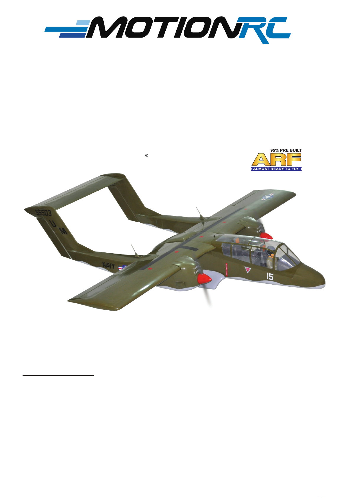
INSTRUCTION MANUAL OV-10 BRONCO
2
Cut off excess.
BApply epoxy glue.
Apply threadlocker
(screw cement).
C.A
Apply instant glue
(C.A glue, super glue).
Cut off shaded portion
carefully.
Assemble left and right
sides the same way.
Must be purchased
separately!
Ensure smooth, non-binding
movement when assembling.
Warning!
Set all scerws securely. If they come off during
flight you will lose control of your aircraft!
Pay close attention here. Drill holes using the stated.
(in this case 1.5mm ).
1.5mm
Take particular care here.
The number of times
the same way Assembly
(in this case twice).
2
Symbols used throughout this instruction manual, comprise:
TABLE OF CONTENTS
►Symbols used throughout this instruction manual,
comprise.....................................................................2
► Warranty................................................................3
► Disclaimer..............................................................3
►Safety precaution...................................................3
►Important bulding notes.........................................3
►Suggestion.............................................................3
►Flight warnings......................................................3
►Covering tools........................................................4
►Adhesives and required tools................................4
►Academy of Model Aeronautics National Model
Aircraft Safety Code...................................................4
►Parts listing (not included).....................................6
►Tool & supplies needed.........................................6
►Preparation............................................................6
►Installing the ailerons and flaps..............................8
►Installing the ailerons and flaps servos...................8
►Installing the control horns and linkages...............10
►Rudder installation...............................................12
►Horizontal stabilizer installation............................16
►Installing the engine.............................................16
►Installing the stopper............................................18
►Installing the fuel tank..........................................19
►Installing the throttle.............................................20
►Installing the electric motor ( ep version )............21
►Installing the wheel well........................................23
►Installing the main gear.......................................25
►Installing the Electric gear retracts.......................26
►Installing the the nose gear..................................27
►Installing the cowling............................................30
►Installing the spinner............................................34
►Installing the Plastic parts for fuselage...............36
►Installing the receiver and battery........................36
►Installing the switch..............................................36
►Installing the Wing attachment, horizontal stabiliz-
er.............................................................37
►Installing the cockpit fuselage...............................39
►Balancing.............................................................41
►Lateral balance....................................................42
►Control throws.....................................................42
►Pre-flight check....................................................42
► For your radio installation basic connection for
airplane and adjustment of servos...........................43
► Main gear dimensional detail...............................44
►Decoration...........................................................45
►Exploded view.....................................................46
► I/C Flying warning................................................47