www.motionrc.com
Motion RC Supplemental Guide for the Detrum GAVIN-8C Transmitter Page 8
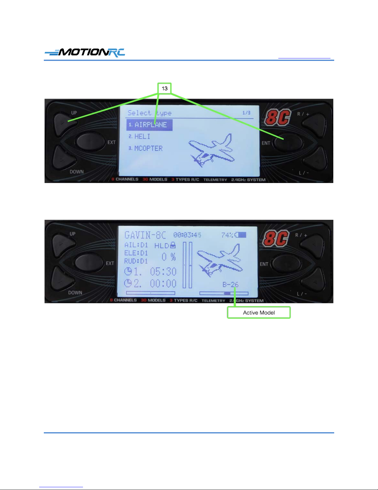
select the model you want to program. Confirm that the model you want to program is
shown and has been bound to the receiver.
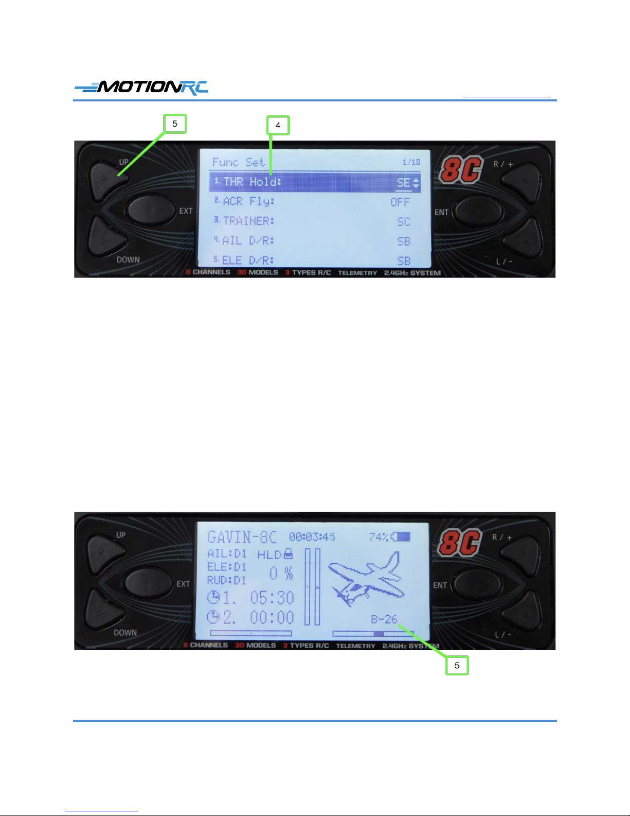
6. Check to ensure HLD appears on the home screen, indicating the throttle hold is active; if
you don’t see HLD, move the throttle switch that you set in step 5 of the previous task to
the opposite position; if you are using switch SF, this requires one click while if you
selected one of the three-position switches, you need to move the switch through two
clicks. HLD should appear on the home screen, which means the throttle is inactive and
programming the model is safer because you won’t get unintended prop or EDF spinning.
If HLD doesn’t appear, perform the steps in the previous task to ensure you have
configured a throttle hold switch.
7. Connect a battery to the ESC. You should hear the startup tones from the ESC and see a
solid light on the receiver.
8. Ensure that a spinning prop or EDF is not a safety hazard, set the throttle switch to the off
position (NORM appears on the home screen indicating the throttle is in normal
operation mode), and slowly advance the throttle to ensure the motor spins.
9. Return the throttle hold switch to the on position so the motor no longer spins; you see
HLD on the home screen.
10. Systematically check each control surface for movement including rudder, ailerons,
elevator, flaps, and retracts. You can change direction and amount of movement later,
now you are ensuring the transmitter can activate the controls correctly.
11. After you’ve confirmed all the model’s controls are working, you are ready to do the
detailed programming of the model.
Program Servo Direction
1. Set the correct direction for each servo using the Rev Set function; to access this from the
home screen, press ENT, select Model Parameter, press ENT, select Rev Set, and press
ENT. You move to the Rev Set screen where you see the current servo direction (Norm
or Rev) for each channel. You also see a visual representation of the channel’s position
and direction of motion on the right side of the screen. The numbers on the far right are
the current trim setting for the channels.
2. Check the direction of motion for a control surface, such as the elevator. If the direction
needs to be reversed, perform step 3; if not, skip to step 4.