MTS Sensors Level Plus User manual

Interface Manual HART®
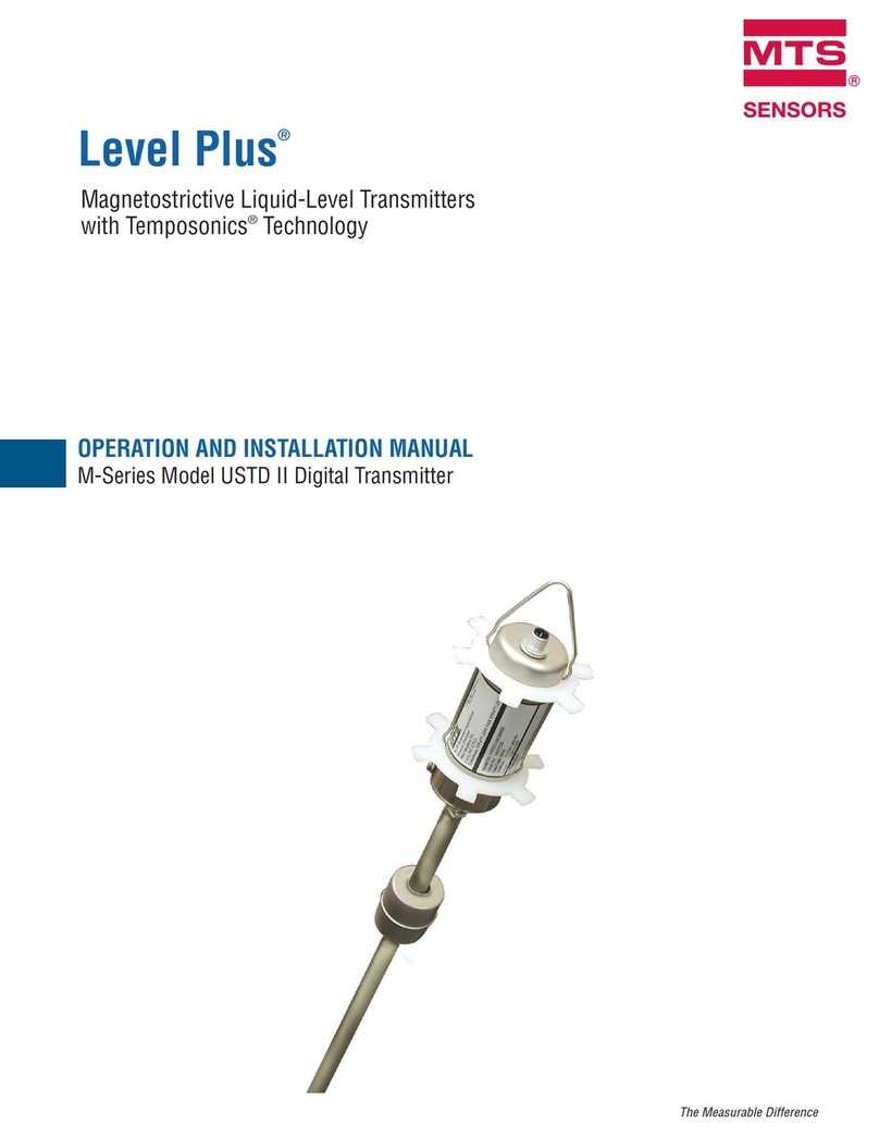
Operation Manual
Level Plus®
Magnetostrictive Liquid Level Transmitters
with Temposonics®Technology

Table of contents
1. Contact information ........................................................................................................................................... 3
2. Terms and definitions ......................................................................................................................................... 4
3. Introduction..................................................................................................................................................... 6
3.1 Purpose and use of this manual ................................................................................................................................................................ 6
3.2 Used symbols and warnings ..................................................................................................................................................................... 6
4. Safety instructions............................................................................................................................................. 6
4.1 Intended use.............................................................................................................................................................................................. 6
5. Product overview .............................................................................................................................................. 6
5.1 Before you begin ....................................................................................................................................................................................... 6
5.2 Quick start-up procedure........................................................................................................................................................................... 6
6. Display Menu................................................................................................................................................... 6
6.1 Operation Modes....................................................................................................................................................................................... 7
6.2 Display Diagram ........................................................................................................................................................................................ 7
6.3 Menu Structure ......................................................................................................................................................................................... 8
7. Alarms........................................................................................................................................................... 8
7.1 Software Fault Alarm ................................................................................................................................................................................. 8
7.2 Hardware Fault Alarm................................................................................................................................................................................ 8
8. Alarms........................................................................................................................................................... 9
9. HART®Interface...............................................................................................................................................10
9.1 LP Dashboard.......................................................................................................................................................................................... 10
9.2 Handheld Programming .......................................................................................................................................................................... 14

Interface Manual HART®
Operation Manual
I3 I
1. Contact information
United States
General
Tel: +1-919-677-0100
Fax: +1-919-677-2343
E-mail: [email protected]
http://www.mtssensors.com
Mailing and shipping address
MTS Systems Corporation
Sensors Division
3001 Sheldon Drive
Cary, North Carolina, 27513, USA
Customer service
Tel: +1-800-633-7609
Fax: +1-800-498-4442
E-mail: [email protected]
Technical support and applications
24 Hour Emergency Technical Support
Tel: +1-800-633-7609
E-mail: [email protected]
Germany
General
Tel: +49-2351-9587-0
Fax: +49-2351-56491
E-mail: [email protected]
http://www.mtssensors.com
Mailing and shipping address
MTS Sensor Technologie GmbH & Co. KG
Auf dem Schüffel 9
58513 Lüdenscheid, Germany
Technical support and applications
Tel: +49-2351-9587-0
E-mail: [email protected]
http://www.mtssensors.com

Interface Manual HART®
Operation Manual
I4 I
2. Terms and definitions
6A Heavy Oils
‘Generalized Crude Oils’, Correction of Volume to 60 °F against API
Gravity.
6B Light Oils
‘Generalized Products’, Correction of Volume to 60 °F against API
Gravity.
6C Chemical
‘Volume Correction Factors (VCF)’ for individual and special
applications, volume correction to 60 °F against thermal expansion
coefcients.
6C Mod
An adjustable temperature reference for dening VCF.
A
API gravity
The measure of how heavy or light a petroleum liquid is compared to
water. Allowable values are 0 to 100 degrees API for (6A) and 0 to 85
degrees API for (6B).
D
DDA (Direct Digital Access)
The proprietary digital protocol developed by MTS for use in
intrinsically safe areas.
Density
Mass divided by the volume of an object at a specic temperature. The
density value should be entered as lb / cu. ft..
E
Explosion proof
Type of protection based on enclosure in which the parts which can
ignite an explosive gas atmosphere are placed within, and which
can withstand the pressure developed during an internal explosion
of an explosive mixture, and which prevents the transmission of the
explosion to the explosive gas atmosphere surrounding the enclosure.
F
Flameproof
Type of protection based on enclosure in which the parts which can
ignite an explosive gas atmosphere are placed within and which can
withstand the pressure developed during an internal explosion of
an explosive mixture, and which prevents the transmission of the
explosion to the explosive gas atmosphere surrounding the enclosure.
G
GOVI (Gross Observed Volume of the Interface)
The total volume of the tank occupied by the interface liquid. The
GOVI is only given when measuring two liquids and is calculated by
subtracting the volume of the product from the total volume of liquid
in the tank (GOVT – GOVP).
GOVP (Gross Observed Volume of the Product)
The total volume of the tank occupied by the product liquid. When
measuring only one liquid, it is also the total volume of liquid
in the tank (GOVT). When measuring two liquids it is the total
volume of liquid in the tank minus the volume of the interface liquid
(GOVT–GOVI).
GOVT (Total Gross Observed Volume)
The total volume of liquid in the tank. When measuring only one liquid
it is equal to the volume of the product (GOVP). When measuring two
liquids it is equal to the volume of the product and interface liquids
(GOVP + GOVI).
GOVU (Gross Observed Volume Ullage)
The difference in volume between the working capacity of a tank and
the total volume in the tank (Working Capacity – GOVT).
H
HART®
A Bidirectional communication protocol that provides data access
between intelligent eld instruments and host systems.
I
Interface
Noun; The measurement of the level of one liquid when that liquid is
below another liquid.
Interface
Adj.; The Software Graphical User Interface (GUI) that allows the user
to access software protocols (HART®, DDA, MODBUS).
Intrinsic safety
‘Intrinsically safe’ - Type of protection based on the restriction of
electrical energy within apparatus of interconnecting wiring exposed to
potentially explosive atmosphere to a level below that which can cause
ignition by either sparking or heating effects.
L
LRV - Lower Range Value
Parameter in HART for controlling where the 4 mA set point.

Interface Manual HART®
Operation Manual
I5 I
M
Mass
The property of a body that causes it to have weight in a gravitational
eld, calculated by density at the reference temperature multiplied by
the volume correction factor (Density × VCF).
MODBUS
A serial communications protocol published by Modicon in 1979 for
use with its programmable logic controllers (PLCs). It has become a
de facto standard communications protocol in industry, and is now the
most commonly available means of connecting industrial electronic
devices.
N
NEMA Type 4X
A product Enclosure intended for indoor or outdoor use primarily to
provide a degree of protection against corrosion, windblown dust and
rain, splashing water, and hose-directed water; and to be undamaged
by the formation of ice on the enclosure. They are not intended to
provide protection against conditions such as internal condensation or
internal icing.
NPT
U.S. standard dening tapered pipe threads used to join pipes and
ttings.
NSVP (Net Standard Volume of the Product)
The temperature corrected volume for the product liquid in the tank,
requires the transmitter to be ordered with temperature measurement
capabilities. The NSVP is calculated by multiplying the volume of the
product liquid by a volume correction factor based on temperature
(GOVP × VCF).
P
PV - Primary Variable
First variable in HART®that is communicated. PV is set to Loop 1
(Product Level) by default. For SIL 2 capable units Loop 1 cannot be
changed fro PV.
R
Reference Temperature
The temperature at which the density measurement is given, the
allowable values are 32 °F to 150 °F (0 °C to 66 °C).
S
Specific Gravity
The density ratio of a liquid to the density of water at the same
conditions.
Sphere Radius
The internal radius of the sphere that contains the liquid, the value is
used to calculate the volume along with the Sphere Offset.
Sphere Offset
An offset value that accounts for additional volume in a sphere from
non-uniform sphere geometry, the value is used to calculate the
volume along with the Sphere Radius.
Strap Table
A table of measurement correlating the height of a vessel to the
volume that is contained at that height. The transmitter can contain up
to 100 points.
SV - Secondary Variable
Second variable in HART®that is communicated. SV is set to Loop
2 (Interface Level) by default unless temperature is ordered and the
temperature is default.
T
TEC
‘Thermal Expansion Coefcient’ - a value correlating the change in
temperature for an object with the change in its volume. Allowable
values are 270.0 to 930.0. TEC units are in 10 E-6/Deg F.
Temperature Correction Method
One of ve product correction methods used to correct the product
volume in the tank due to changes in temperature from 60 °F including
(6A, 6B, 6C, 6C Mod, and Custom Table.
TV - Tertiary Variable
Third variable in HART®that is communicated. TV is set to
temperature by default.
U
URV - Upper Range Value
Parameter in HART®for controlling where the 20 mA set point.
V
Volume Calculation Mode
One of two methods use to calculate volume measurements from level
measurements, including Sphere and Strap Table.
VCF (Volume Correction Factor)
A table of measurements correlating temperature points with
correction factors for the liquids expansion/contraction. The
transmitter can contain up to 50 points.
W
Working Capacity
The maximum volume of liquid that the user desires for their vessel to
hold, typically 80 % of the vessels maximum volume before overll.

Interface Manual HART®
Operation Manual
I6 I
3. Introduction
3.1 Purpose and use of this manual
Important:
Before starting the operation of the equipment read this
documentation thoroughly and follow the safety information.
The content of this technical documentation and of its various
annexes is intended to provide information on the HART®Interface of
the LP Series. All safety related information is in the product specic
operation manual.
3.2 Used symbols and warnings
Warnings are intended for your personal safety and for avoidance
of damage to the described product or connected devices. In this
documentation, safety information and warnings to avoid dangers that
might affect the life and health of personnel or cause material damage
are highlighted by the preceding pictogram, which is dened below.
Symbol Meaning
NOTICE
This symbol is used to point to situations
that may lead to material damage and/or
personal injury.
4. Safety instructions
4.1 Intended use
The purpose of this document is to provide detailed information on
the protocol interface. All safety related information is in the product
specific operation manual. Consult the operation manual before
connecting to the level transmitter.
5. Product overview
5.1 Before you begin
NOTICE
Output will vary depending on the location of the 4 and 20 mA set
points.
Tools needed:
• 24 Vdc linear regulated power supply
• Current meter
5.2 Quick start-up procedure
1. Connect 24 Vdc power supply to Loop 1.
2. Turn on power supply.
3. Connect Current Meter to test pins on interconnect board. Loop 1
Test Pins are on the bottom left and labeled TP1 and TP2.
4. Move the float towards the tip of the pipe and verify 4 mA set
point.
5. Move the float towards the top of the pipe and verify 20 mA set
point.
6. If using two floats, repeat steps 4 and 5 for second float. Test pins
for Loop 2 are TP5 and TP6. Note both floats must be present or
else the level transmitter will go into alarm.
7. Turn off power and disconnect power supply and current meter.
8. Install in tank.
6. Display Menu
All LP-Series liquid level transmitters are shipped with a Stylus (MTS
Part # 404108) to be used for manipulating the display. For single and
dual cavity housings, the Stylus is designed to allow for programming
of the unit without removing the housing. For NEMA housings the
housing must be removed to access the display. Place your nger
between the display and stylus for correct spacing. When using the
Stylus make sure to align the Stylus with the shape outline around the
buttons in the same orientation. Failure to correctly align the Stylus
can cause the display to not function properly.
NOTICE
Do not use any device other than the MTS Stylus to operate the
display on the LP Series.
NOTICE
Improper use of the Stylus can cause the display to not function
properly.

Interface Manual HART®
Operation Manual
I7 I
6.1 Operation Modes
The LP Series level transmitter runs in one of the following modes of
operation. You can use these modes to calibrate and set up various
operating parameters.
6.1.1 Run Mode
Run mode is the primary mode of operation. This mode will perform
measurements, display data, and respond to HART®commands.
6.1.2 Program Mode
Program mode is the primary mode for commissioning and
troubleshooting the level transmitter. The full menu and available
functions are shown in section 6.3 Menu Structure. To enter program
mode use the Stylus and press the Enter Key as shown in section 6.2
Display Diagram. Program Mode is protected by a password to keep
unwarranted changes from occurring.
When in program mode, remote communications are not functional.
An automatic timeout feature is provided so that the transmitter
does not remain inadvertently in program mode. The timeout is set
for 1minute before prompted for additional time. Total timeout is
2minutes.
NOTICE
Whenever program mode is exited from the display the unit will
reset itself to insure all changes have been accepted. The reset will
take approximately 5 seconds before the level transmitter is able to
respond to commands.
NOTICE
In program mode, the transmitter will not respond to incoming
HART®commands. A busy error will be sent to the controller to
notify the unit is in program mode. This function will prevent a user
at a remote terminal from programming the unit while a user is
accessing program mode from the display.
Fig. 1: Display
6.2 Display Diagram
Key / Element Function
UP Arrow Used to move cursor on screen up and to
increment number
DOWN Arrow Used to move cursor on screen down and to
decrease number
SCROLL Arrow Used to move cursor on screen to the right,
cursor will cycle back
ENTER Key Used to Enter Program Mode, select Highlighted
Item, and Conrm Selection
EXIT Key Hidden key in the middle of the display that is
used to exit menu at any time
MEASURED
VARIABLE
The process variable that is selected to display.
The display will automatically scroll between
selected variables.
MEASUREMENT The numerical value for the MEASURED
VARIABLE shown on the display.
UNITs Unit of measurement for the MEASURED
VARIABLE shown on the display.
TEMPERATURE Average temperature for the product in the tank.
Only shown if the level transmitter was purchased
with temperature.
NOTIFICATIONS Four squares with letters. Top left square is blank.
Top right square, A, will only show when there
is an alarm. Toggle the UP Arrow key to view
alarms. Bottom right square, F, will only show
when there is a fault. Toggle the DOWN Arrow key
to view error codes. Bottom left square, P, will
only show when the units is being programmed
remotely.
NOTICE
The factory default password is 27513.

Interface Manual HART®
Operation Manual
I8 I
6.3 Menu Structure
Go to section 9.3 for more information about how to program the unit
from the display.
Data From Device
• Display
• Units
• Length Units
• Temp Units
• Set Points
• Prod LVR (4 mA)
• Prd URV (20 mA)
• Prd Current LRV
• Prd Current URV
• Int LRV (4 mA)
• Int URV (20 mA)
• Int Current LRV
• Int Current URV
• Alarm Select
• Signal Strength
• Prod Trig Lvl
• Int Trig Lvl
Calibrate
• Product Level
• Current Level
• Offset
• Interface Level
• Current Level
• Offset
Factory
• Settings
• Gradient
• Serial Number
• HW Revision
• SW Revision
• SARA Blanking
• Magnet Blanking
• Gain
• Min Trig Level
• Reverse Measure
• Temp Setup
• Temp Enable
• No of Temp
• Float Config
• Loop 1
• Loop 2
• Damping
• Loop 1
• Loop 2
• Auto Threshold
• Reset to Factory
7. Alarms
MTS has two separate types of alarms featuring both a software fault
alarm and a hardware fault alarm.
7.1 Software Fault Alarm
MTS offers a software fault alarm that will force the 4…20 mA output
into an either a low or high alarm state. The default setting from the
factory is a low alarm state. The low alarm state is ≤ 3.6 mA and the
high alarm state is ≥ 21 mA. The software fault alarm follows the
recommendations set forth by NAMUR NE 43. Typical faults that
will cause a software fault alarm are a missing oat, the oat in the
inactive range, and the level transmitter looking for the wrong number
of oats.
7.2 Hardware Fault Alarm
MTS offers a hardware fault alarm that will force the 4…20 mA output
into a low alarm. The hardware low alarm is 3.2 mA. The hardware low
alarm is triggered when the internal diagnostics of the level transmitter
have detected a hardware issue with the 4…20 mA output.

Interface Manual HART®
Operation Manual
I9 I
8. Alarms
Fault
Code
Description Corrective Action
101 Missing
Magnet
• Verify Float Configuration is correct for the
number of floats installed.
• Verify Float(s) are not in inactive zone.
• Verify Auto Threshold is enabled.
• Cycle power to sensor. If proper operation is
not restored, Contact Factory.
102 Internal
Fault 1
Cycle power to sensor. If proper operation is not
restored, Contact Factory.
103 Internal
Fault 2
Cycle power to sensor. If proper operation is not
restored, Contact Factory.
104 Internal
Fault 3
Cycle power to sensor. If proper operation is not
restored, Contact Factory.
105 Lobe Fault
1
• Verify Auto Threshold is enabled.
• Cycle power to sensor.
• If proper operation is not restored, Contact
Factory.
106 Lobe Fault
2
• Verify Auto Threshold is enabled.
• Cycle power to sensor.
• If proper operation is not restored, Contact
Factory.
107 Delta Fault The change in level output exceeded the Delta
limit. The Delta can be adjusted if the process is
changing quickly or this can be an indication of
electrical noise. Check grounding and shielding
before adjusting the Delta value.
108 Internal
Fault 4
Cycle power to sensor. If proper operation is not
restored, Contact Factory.
109 Peak Fault • Verify Auto Threshold is enabled.
• Cycle power to sensor.
• If proper operation is not restored, Contact
Factory.
110 Hardware
Fault 1
Cycle power to sensor. If proper operation is not
restored, Contact Factory.
111 Power Fault • Cycle power to sensor.
• Verify Power Supply rating.
• Verify wiring.
• If proper operation is not restored, Contact
Factory.
112 Hardware
Fault 2
Cycle power to sensor. If proper operation is not
restored, Contact Factory.
113 Hardware
Fault 3
Cycle power to sensor. If proper operation is not
restored, Contact Factory.
114 Hardware
Fault 4
Cycle power to sensor. If proper operation is not
restored, Contact Factory.
115 Timing
Fault 1
Cycle power to sensor. If proper operation is not
restored, Contact Factory.
116 Timing
Fault 2
Cycle power to sensor. If proper operation is not
restored, Contact Factory.
117 Timing
Fault 3
Cycle power to sensor. If proper operation is not
restored, Contact Factory.
Fault
Code
Description Corrective Action
118 DAC Fault 1 Cycle power to sensor. If proper operation is not
restored, Contact Factory.
119 DAC Fault 2 Cycle power to sensor. If proper operation is not
restored, Contact Factory.
120 DAC Fault 3 Cycle power to sensor. If proper operation is not
restored, Contact Factory.
116 DAC Fault 4 Cycle power to sensor. If proper operation is not
restored, Contact Factory.
117 SPI Fault 1 Cycle power to sensor. If proper operation is not
restored, Contact Factory.
118 SPI Fault 2 Cycle power to sensor. If proper operation is not
restored, Contact Factory.
119 Setpoint
Fault
The analog setpoints are too close. Minimum
distance is 150 mm (6 in.) for analog and 290
mm (11.5 in.) for SIL. Adjust programmed
setpoints as needed. (Analog only) If proper
operation is not restored, Contact Factory.
120 Loop 1 Out
of Range
Verify that magnets are positioned within
expected measuring range. Adjust programmed
setpoints as needed. (Analog only) If proper
operation is not restored, Contact Factory.
121 Loop 2 Out
of Range
Verify that magnets are positioned within
expected measuring range. Adjust programmed
setpoints as needed. (Analog only) If proper
operation is not restored, Contact Factory.
122 EEPROM
Fault 1
Cycle power to sensor. If proper operation is not
restored, Contact Factory.
123 EEPROM
Fault 2
Cycle power to sensor. If proper operation is not
restored, Contact Factory.
124 Flash
Failure
Cycle power to sensor. If proper operation is not
restored, Contact Factory.
125 Internal
Error
Cycle power to sensor. If proper operation is not
restored, Contact Factory.
126 Loop 2 Out
of Range
Verify that magnets are positioned within
expected measuring range. Adjust programmed
setpoints as needed. (Analog only) If proper
operation is not restored, Contact Factory.
127 EEPROM
Fault 1
Cycle power to sensor. If proper operation is
not restored, Contact Factory.
128 CRC Fault Reset CRC using LP Dashboard or Handheld
HART Communicator
129 Flash
Failure
Cycle power to sensor. If proper operation is
not restored, Contact Factory.
130 Internal
Error
Cycle power to sensor. If proper operation is
not restored, Contact Factory.
Interface Manual HART®
Operation Manual
I10 I
9. HART®Interface
MTS Sensors has tested and is compliant to HART®ITK 7.2.
The device driver le is available for download from HART®
Communication Protocol website at: www.hartcomm.org or from MTS
Sensors at: www.mtssensors.com.
Programming via HART®can be done either using the LP Dashboard
via a HART®modem or a handheld programmer.
9.1 LP Dashboard
9.1.1 Installing LP Dashboard
Adjustments to the setup and calibration of the HART®Interface can
be performed using the MTS LP Dashboard. The Dashboard can
be run from any Windows 7 or newer OS using a HART®to USB
converter (MTS part #380068).
Perform the following steps to install the LP Dashboard and establish
communication:
1.Install LP Dashboard from the USB stick that came with the level
transmitter or go to www.mtssensors.com to download the latest
version.
2.Connect level transmitter to HART®to USB converter, connect
24Vdc power to the level transmitter, and connect the HART®to
USB converter to the PC. Example setup shown below.
NOTICE
Power must be on Loop 1 for HART®communication to work.
Power does not have to be applied on Loop 2 for HART®to work.
Power must be applied to Loop 2 to check current output.
NOTICE
HART®requires a load resistor to work correctly. Add a 250 Ohm
resistor for proper communication. Some PLC cards will have built
in load resistors.
Fig. 2: Example setup
3.Open setup software and select HART®protocol from drop down
menu.
Level Transmitter
Hart®/ USB
Converter
Power supply
Computer
24 Vdc
Gnd
4.Select COM Port. Software will show active COM ports. Make
sure converter is connected before starting LP Dashboard or
COM port will not show.
Fig. 3: Initial screen
Fig. 4: Home screen
9.1.2 Home screen
The LP Dashboard Home Screen will look different based on whether
or not temperature has been ordered. If the level transmitter includes
temperature measurement then the Home Screen will look as shown.
If the level transmitter does not include temperature measurement
then the Home Screen will not show the middle panel for temperature.
The Home Screen can be accessed by pressing the three white bars on
the top left.

Interface Manual HART®
Operation Manual
I11 I
Fig. 5: The Configuration tab allows the level transmitter to be configured for the specific
application.
Fig. 6: Signal settings
The level panel on top shows the level measurement for the Product
level and Interface level. If only the product oat is selected then only
the product oat will be shown. The bold numbers are the numerical
level and the graph is a time lapse of the graphical representation of
the numbers. The red line is the approximate maximum level based off
of the order length of the level transmitter. The numbers on the right
of the level panel are the Trigger Level for the Product Float on top
and the Interface Float on bottom. These are a representation of how
strong of a return signal the level transmitter is experiencing.
The temperature panel will only show if temperature measurement
was ordered and turned on. The left side shows the numerical value
of temperature. The bar graph in the middle of the panel shows
temperature measurement point.
Across the bottom of the Home Screen is the visual indication of the
fault codes from section 8. Green indicates no fault and red indicates
fault. Next is the rmware version in the middle followed by the serial
number.
9.1.3 Configuration
Temperature: Default setting of OFF if ordered without temperature.
Default setting of ON if ordered with temperature. Turning temperature
ON when the level transmitter was not ordered with temperature will
not cause temperature to work and will force the level transmitter into
Fault.
Filtering: An internal ltering process for the temperature
measurement. Filtering should be ON.
6” Delta: Internal setting. Leave ON.
Display Enable: Default setting of ON. Display can be turned off by
changing to OFF and cycling power.
LOOP2 Present: Internal ag to turn on Loop 2. Changing this will not
allow a second loop unless the hardware was ordered with a second
loop.
User Configurable
Reverse Measure: Allows the end user to change the direction in
which the MTS level transmitter counts. The default setting is OFF and
the level transmitter will reference the tip of the pipe/hose and count
up from the tip. The ON setting will reference the head of the level
transmitter and count up as it moves towards the tip.
Device Address: The end user can congure the HART®address
if being used in a multidrop network. Default address is 0. Do not
change from 0 unless all communication will be done via HART®as
the current loop will not respond in multidrop mode.
Display Setting: Allows the end user to congure the display.
Available options are level in engineering units, current (mA), or
percentage full. Default setting is level.
Alarm Setting: Allows the end user to congure a High (>21 mA)
or Low (<3.6 mA) alarm for level transmitter. Default setting is Low
(<3.6mA) alarm.
9.1.4 Signal settings
Factory Set
Auto Threshold: Default setting is ON and should not be turned off.
This feature allows the unit to automatically adjust the threshold for
optimal performance.
Lobe Test: A functional test to make sure the return signal from MTS
has the correct shape. Lobe Test should be on unless using a magnet
not supplied by MTS.
Noise Detection: A functional test to determine if noise is entering the
MTS level transmitter.
Product Float: Default setting of ON for all applications.
Interface Float: Default setting of ON if ordering 2 Loops. Default
setting of OFF if ordering 1 Loop. If the number of oats turned on is
different from the number of oats physically on the level transmitter
the level transmitter will go into Fault.
Serial Number: Serial Number assigned by MTS at the time of
manufacture. The serial number is used for tracking and replacement
parts. HART®only displays 6 of 8 digits. Do not change.
Factory Set
Gradient: Is the speed at which the magnetostrictive signals travel
along the sensing element. Typical range is from 8.9 to 9.2. Do not
change unless replacing the sensing element. Changing this number
will directly affect accuracy.

Interface Manual HART®
Operation Manual
I12 I
Signal Gain: Is the strength of the interrogation pulse. MTS uses the
same electronics for all lengths and adjusts the signal based on the
order length. Do not change unless instructed to do so by the MTS
Factory.
9.1.5 Level settings
Fig. 7: Level settings
Fig. 8: Temperature settings
Fig. 9: Analog settings
Factory Set
Method – Enter Level Offset: a calibration method that directly
changes the offset of the level measurement. The offset is the zero
reference point used in determining the level output. Do not use
without Factory guidance.
Product Offset: the full length of the level transmitter including order
length, inactive zones, and mounting length. Do not change the Enter
Level Offset method without Factory guidance. The offset will change
after using the Enter Current Tank Level for the Product. The Product
Offset and Interface Offset are independent of one another.
Interface Offset: the full length of the level transmitter including order
length, inactive zones, and mounting length. Do not change the Enter
Level Offset method without Factory guidance. The offset will change
after using the Enter Current Tank Level for the Interface. The Product
Offset and Interface Offset are independent of one another.
User Configurable
Length Units: the unit of measurement used for engineering units.
Default is inches if ordered in inches and mm if ordered in mm.
Options include inches, feet, millimeters, centimeters, and meters.
Method – Enter Current Tank Level: a calibration method that
calibrates the level transmitter based off of one point of measurement.
Select Enter Current Tank Level from the Method drop down box. Go
to Product Level and enter value of current product level based off
of a manual measurement while the tank level is not changing. Go to
Interface Level and enter value of current interface level based off of
a manual measurement while the tank is not changing. Click Update
box in lower left corner when it appears. Level transmitter is now
calibrated.
9.1.6 Temperature settings
User Configurable
Product Zero: Chang the Zero (LRV, 4mA) set point of the product
level. The set point needs to be in the active range.
Product Span: Chang the Span (URV, 20mA) set point of the product
level. The set point needs to be in the active range.
Factory Set
Position: The location of the temperature sensor in reference to the
end of the pipe.
Slope: Calibration factor for the temperature sensor. Do not change
unless a new sensing element with temperature is ordered.
Intercept: Calibration factor for the temperature sensor. Do not change
unless a new sensing element with temperature is ordered.
User Configurable
Temperature Units: Change the units of measure for the temperature
settings. Options are Fahrenheit or Celsius.
Number of Averages: Change the number of temperature readings
used in the rolling average.
9.1.7 Analog settings

Interface Manual HART®
Operation Manual
I13 I
Fig. 10: Flash settings
Fig. 11: Save settings
9.1.9 Save settingsInterface Zero: Chang the Zero (LRV, 4mA) set point of the interface
level. The set point needs to be in the active range.
Interface Span: Chang the Span (URV, 20mA) set point of the
interface level. The set point needs to be in the active range.
Temp Zero: Chang the Zero (LRV, 4mA) set point of the temperature.
The set point needs to be in the active range. The Temp Zero needs to
be less than the Temp Span.
Temp Span: Chang the Span (URV, 20mA) set point of the
temperature. The set point needs to be in the active range. The Temp
Zero needs to be less than the Temp Span.
Product Damping: Slows the rate of change of the product level.
Default setting is 0.4s.
Interface Damping: Slows the rate of change of the interface level.
Default setting is 0.4s.
Temp Damping: Slows the rate of change of the temperature. Default
setting is 0.4s.
PV: Select the process variable that is used as the PV in HART®and
Loop 1 output. Product, Interface, or Temperature can be used.
SV: Select the process variable that is used as the SV in HART®and
Loop 2 output. Product, Interface, or Temperature can be used. SV can
be same as PV.
TV: Select the process variable that is used as the TV in HART®.
Product, Interface, or Temperature can be used. TV can be the same
as SV and/or PV.
9.1.8 Flash settings
NOTICE
A copy of the backup file is maintained by MTS including all factory
parameteres as the level transmitter was originally setup after
completing testing and calibration at the MTS factory. MTS can
provide a copy of the backup file upon request based off of the serial
number of the level transmitter. Contact MTS Technical Support for
assistance.
User Configurable
Reset to Factory Defaults: Allows the end user to reset all settings
back to the original settings as they were when they left the MTS
factory. This is intended to be used as a rst step in troubleshooting.
Do note, the Zero and Span set points will reset to factory settings.
Fix fault code 128: If fault code 128 appears red then click the link on
the Dashboard to clear the fault.
Cycle power the device: Allows the end user to have the level
transmitter automatically turn power off, turn power on, and reboot
the device.
User Configurable
Read Settings from File: Allows the end user to upload factory
parameters from a backup le to the LP Dashboard. This task is
usually performed from a saved backup le or the original backup le
maintained by MTS.
Write Setting to a File: Allows the end user to download a backup
le of factory parameters from the LP Dashboard to a PC. This task is
usually performed after Read Settings from Gauge. Note – wait until all
settings have changed from Red to White before writing as the color
change signals that the settings have been updated.
Write Settings to Gauge: Allows the end user to program the
level transmitter with the factory parameters displayed on the LP
Dashboard. This task is usually performed after Read Settings from
File.
Read Settings from Gauge: Allows the end user to update all of the
factory parameters displayed on the screen. All settings will turn Red
and then will turn white as they are updated.

Interface Manual HART®
Operation Manual
I14 I
9.2 Handheld Programming
9.2.1 Handheld Menu Tree
Device Setup
Write Protect (Must be disabled to show complete menue tree
Process Variables
PV
SV
TV
Diag/Service
Test Device
Status
Self Test
Loop Test
4 mA
20 mA
Other
Set Factory Values
Set Data CRC
Power Cycle Device
Basic Setup
Tag
PV Unit
PV LRV
PV URV
PV Damp
Device Information
Detailed Setup
Variable mapping
Conguration
Sys Cong
Alarm
Level 1
Level 2
Temperature
Display
Display Setting
Lobe Count
Gradient
Offsets
Float 1 Offset
Float 2 Offset
LCD settings
Screen delay
Screen contrast
Sensors
Level 1
Level 1 Unit
Level 1
Level 1 Class
Level 1 LRV
Level 1 URV
Level 1 Min Span
Level 1 Damp
Level 2
Level 2 Unit
Level 2
Level 2 Class
Level 2 LRV
Level 2 URV
Level 2 Min Span
Level 2 Damp
Temp
Temp Unit
Temp
Temp Class
Temp LRV
Temp URV
Temp Min Span
Temp Damp
HART ouput
Poll addr
Num reg preams
Device Information
Review
PV
PV Loop Current
PV LVR
PL URV

Interface Manual HART®
Operation Manual
I15 I
9.2.2 Handheld Menu Screenshots
9.4.2.1 Online Menu Screen
Fig. 12: Online Screen
Fig. 13: Write Protect Enabled Screen
Fig. 14: Write Protect Disabled
Fig. 15: Process Variable Screen
Parameters
No Editable Parameters
Data
PV, PV Loop current, PV LVR, and PV URV are all shown on screen
9.4.2.2 Device setup Menu Screen
Parameters
Write Protect - user can turn disable or enable write protect mode.
While write protect is enable no variables can be changed and the full
menu tree cannot be seen.
Data
No Data is displayed
9.4.2.3 Process variables Menu Screen
Parameters
PV – Primary Variableis the HART®parameter that is by default
mapped to the Product Level. This can be changed using Variable
mapping feature. SIL2 Capable units do not allow the PV to be
changed.
SV – Secondary Variable is the HART®parameter that is mapped to the
Interface Level unless Temperature is ordered. This can be changed
using the Variable mapping feature.
TV – Tertiary Variable is the HART®parameter that is mapped to
the Temperature by default. This can be changed using the Variable
mapping feature.
Data
No Data is displayed

Interface Manual HART®
Operation Manual
I16 I
9.4.2.4 PV Menu Tree
Fig. 16: PV Menu Tree Fig. 18: TV Menu Tree
Fig. 19: Diag/Service Menu Screen
Fig. 17: SV Menu Tree
Parameters
Level 1 LRV – lower range value of the PV that correlates to the
location of the 4 mA set point of the output.
Level 1 URV – upper range value of the PV that correlates to the
location of the 20 mA set point of the output.
Data
Level 1 – the product level is displayed.
PV% rnge – the percentage (0 to 100%) of the active range that the
process variable is currently at.
PV Loop current – the current output level of the PV based on the
settings of the LRV, URV, and Level 1
9.4.2.5 SV Menu Tree
Parameters
Level 2 LRV – lower range value of the SV that correlates to the
location of the 4 mA set point of the output.
Level 2 URV – upper range value of the SV that correlates to the
location of the 20 mA set point of the output.
Data
Level 2 – the interface level is displayed.
SV% rnge – the percentage (0 to 100%) of the active range that the
process variable is currently at.
SV Loop current – the current output level of the SV based on the
settings of the LRV, URV, and Level 2.
9.4.2.6 TV Menu Screen
Parameters
Temp LRV – lower range value of the TV that correlates to the location
of the 4 mA set point of the output.
Temp URV – upper range value of the TV that correlates to the location
of the 20 mA set point of the output.
Data
Temp – the temperature is displayed.
9.4.2.7 Diag/Service Menu Screen
Parameters
Set Factory Values – clears all programming and resets factory
parameters to default values. Do not perform this function unless
instructed to do so by factory technical support.
Set Data CRC – allows the user to rest the CRC in the level transmitter
and clear the 128 Fault Code.
Power Cycle Device – allows the user to power cycle the level
transmitter without disconnecting power from the unit.
Data
No Data is Displayed

Interface Manual HART®
Operation Manual
I17 I
Fig. 20: Test Device Menu Screen Fig. 22: Loop Test Menu Tree
Fig. 23: Basic Setup Menu Screen
Fig. 21: Status Menu Screen
9.4.2.8 Test device Menu Screen
Parameters
Self Test – allows user to force level transmitter to check for fault
codes. Fault codes would be displayed under Status.
Data
Status – shows any existing fault codes
9.4.2.9 Status Menu Screen
Parameters
No editable parameters
Data
Fault – shows fault codes displayed by level transmitter. These codes
are explained in section 8. Use must run Self Test before fault codes
will appear.
9.4.2.10 Loop Test Menu Tree
Parameters
4 mA – allows the user to force loop test and current output to 4 mA
20 mA – allows the user to force loop test and current output to 20 mA
Other – allows the user to force loop test and current output to
selected level
End – Stops loop test and returns level transmitter to normal output
Data
No data is displayed
9.4.2.11 Basic setup Menu Screen
Parameters
Tag – HART®descriptor that can be edited by user
PV Unit – unit of measure for the PV variable
PV LRV – lower range value of the PV that correlates to the location of
the 4 mA set point of the output.
PV URV – upper range value of the PV that correlates to the location of
the 20 mA set point of the output.
PV Damp – allows the user to select the damping of the PV variable
Data
Device Information – provide detailed information on the setup of the
PV

Interface Manual HART®
Operation Manual
I18 I
9.4.2.12 Detailed setup Menu Screen
Fig. 24: Detailed Setup Menu Screen Fig. 26: Configuration Menu Screen
Fig. 27: Sys Config Menu Screen
Fig. 25: Variable Mapping Menu Screen
Parameters
Variable mapping – allows the user to select the MTS variables that
are mapped to the PV, SV, and TV
Configuration – allows access to several MTS parameters
Offsets – allows access to calibrating the level transmitter
LCD settings – allows access to customizing LCD display
Sensors – allows access to data and programming of PV, SV, and TV
HART output – allows access to setting HART®multidrop network
Data
Device Information – provide detailed information on the setup of the
PV
9.4.2.13 Variable mapping Menu Screen
Parameters
PV is – allows user to select the MTS variable that is mapped to the
PV in HART®
SV is – allows user to select the MTS variable that is mapped to the
SV in HART®
TV is – allows user to select the MTS variable that is mapped to the TV
in HART®
Data
No data is displayed
9.4.2.14 Configuration Menu Screen
Parameters
Sys Config – allows access to MTS factory parameters
Gradient – calibration factor for level transmitter that should not be
changed unless replacing a sensing element.
Data
No data is displayed
9.4.2.15 Sys Config Menu Screen
Parameters
Alarm – allows user to select between a Hi (>21 mA) and Lo (<3.6
mA) alarm setting. Default is a low alarm.
Level 1 – allows user to turn product level on or off. Should always be
on.
Level 2 – allows user to turn interface level on or off. This will not
work if a second oat is not used.
Temperature – allows user to turn temperature on or off. This will not
work unless temperature is ordered on the level transmitter.
Display – allows the user to turn the display on or off. Power must be
cycled for this to take affect.
Display Setting – allows the user to select if the display shows Level,
mA, or %. Default setting is Level.

Interface Manual HART®
Operation Manual
I19 I
Fig. 28: Offsets Menu Screen
Fig. 30: Sensors Menu Screen
Fig. 29: LCD Settings Menu Screen
Lobe Count – allows the user to turn the lobe fault on or off. The lobe
count should be on unless not using a MTS magnet.
Data
No data is displayed
9.4.2.16 Offsets Menu Screen
Parameters
Float 1 Offset – allows user to change the offset of the product level
that is used for calibration. Please contact the factory for technical
support to make this change.
Float 2 Offset – allows user to change the offset of the interface level
that is used for calibration. Please contact the factory for technical
support to make this change.
Data
No data is displayed
9.4.2.17 LCD settings Menu Screen
9.4.2.18 Sensors Menu Screen
Parameters
Level 1 – allows user to access parameters and data for product level.
Level 2 – allows user to access parameters and data for interface
level.
Temp – allows user to access parameters and data for temperature.
Data
No data is displayed
Parameters
Screen delay – allows user to change the update rate of the display.
This should not be adjusted without factory support.
Screen contrast – allows user to change the darkness of the display.
Data
No data is displayed

Interface Manual HART®
Operation Manual
I20 I
Fig. 31: Level 1 Menu Screen
Fig. 33: Temp Menu Screen
Fig. 32: Level 2 Menu Screen
9.4.2.19 Level 1 Menu Screen
Parameters
Level 1 Unit – allows user to change unit of measure for product level.
Level 1 LRV – lower range value of the product level that correlates to
the location of the 4 mA set point of the output.
Level 1 URV – upper range value of the product level that correlates to
the location of the 20 mA set point of the output.
Level 1 Damp – damping parameter for product level
Data
Level 1 – actual product level in units of measure
Level 1 Class – variable class for product level
Level 1 Min span – the minimum distance required between the Level
1 LRV and Level 1 URV
9.4.2.20 Level 2 Menu Screen
Parameters
Level 2 Unit – allows user to change unit of measure for product level.
Level 2 LRV – lower range value of the interface level that correlates
to the location of the 4 mA set point of the output.
Level 2 URV – upper range value of the interface level that correlates
to the location of the 20 mA set point of the output.
Level 2 Damp – damping parameter for interface level
Data
Level 2 – actual product level in units of measure
Level 2 Class – variable class for interface level
Level 2 Min span – the minimum distance required between the Level
2 LRV and Level 2 URV
9.4.2.21 Temp Menu Screen
Parameters
Temp Unit – allows user to change unit of measure for temperature.
Temp LRV – lower range value of the temperature that correlates to
the location of the 4 mA set point of the output.
Temp URV – upper range value of the temperature that correlates to
the location of the 20 mA set point of the output.
Temp Damp – damping parameter for temperature
Data
Temp – actual temperature in units of measure
Temp Class – variable class for temperature
Temp Min span – the minimum distance required between the Temp
LRV and Temp URV
Other manuals for Level Plus
2
Table of contents
Other MTS Sensors Transmitter manuals

MTS Sensors
MTS Sensors Level Plus SoCLEAN User manual

MTS Sensors
MTS Sensors Level Plus M Series Specification sheet

MTS Sensors
MTS Sensors Level Plus User manual

MTS Sensors
MTS Sensors Level Plus Tank SLAYER User manual

MTS Sensors
MTS Sensors Level Plus LP Series User manual

MTS Sensors
MTS Sensors Level Plus M Series Specification sheet

MTS Sensors
MTS Sensors Level Plus SoCLEAN User manual