MotionRC Detrum GAVIN-6C Owner's manual

www.motionrc.com
Motion RC Supplemental Guide for the
Detrum GAVIN-6C
Transmitter
Version 1.0

www.motionrc.com
Motion RC Supplemental Guide for the Detrum GAVIN-6C Transmitter
Contents
Review the Transmitter’s Controls ................................................................................... 1!
Review the Home Screen ................................................................................................. 2!
Power the Transmitter ...................................................................................................... 3!
Callibrate the Transmitter ................................................................................................. 3!
Create a Model ................................................................................................................. 3!
Bind a Receiver to a Model .............................................................................................. 5!
Prepare to Program an Airplane ....................................................................................... 6!
Program Servo Direction .................................................................................................. 7!
Program Servo Range of Motion ...................................................................................... 8!
Program Servo Sub Trim .................................................................................................. 9!
Program Expo .................................................................................................................. 9!
Program Dual Rates ....................................................................................................... 11!
Set Timers ...................................................................................................................... 13!
Perform a Range Test .................................................................................................... 14!

www.motionrc.com
Motion RC Supplemental Guide for the Detrum GAVIN-6C Transmitter Page 1
This guide provides instructions to help you program the Detrum GAVIN-6C for an airplane.
Additional information can be found in the manual included with the radio.
Review the Transmitter’s Controls
1. Power switch—push the switch up to turn the transmitter on.
2. Status light—illuminated when the transmitter is turned on.
3. Trim buttons—push to set the trim for the associated channel.
4. Control sticks—control the channel to which they are connected.
5. GEAR switch—a two-position switch that is usually used for retracts.
6. TRAINER switch—a two-position switch that is spring-loaded; when held against the
spring, the transmitter passes control to another transmitter to which it is connected. You
also use this to bind the transmitter to a receiver.
7. FLAP switch—a two-position switch that can be used for flaps; however, a three-position
switch is more typical for flaps (you can use the FMOD switch for flaps).
8. HOLD switch—a two-position switch that activates throttle hold.
9. FMOD switch—a three-position switch that can be used for a variety of functions.
10. Display screen—displays different pages of information while you are controlling a
model or programming the transmitter. After a time of inactivity, the screen dims. Press a
button to return the screen to full brightness.

www.motionrc.com
Motion RC Supplemental Guide for the Detrum GAVIN-6C Transmitter Page 2
Review the Home Screen
1. System timer—how long the transmitter has been turned on.
2. Battery status—how much charge remains in the batteries by percentage and icon.
3. Dual rate status—when the two bars are the same height, dual rates are turned off and
100% of maximum control movement is provided; when the left bar is half height, dual
rates are turned on and 60% of maximum control movement is provided.
4. Hold indicator—when HLD is displayed, throttle hold is on and the motor won’t spin
when throttle is applied; when NORM is displayed, the throttle is active.
5. Percent of throttle—indicates how much throttle is being applied.
6. Timer 1—displays a countdown or count up timer, typically triggered by throttle or
HOLD switch position. When the timer expires, you hear a tone and the timer flashes.
7. Timer 2—provides a second timer with the same capabilities as timer 1.
8. Trim indicators—the shaded part of the trim indicator indicates how much trim is applied
to the associated channel and in which direction. When you are setting trim, the
numerical value is displayed at the end of the trim indicator.
9. Active model—you see the name of the active model, which means the model that can be
flown or programmed.
10. UP button—use this to highlight options on the screen when you program the transmitter.
11. DOWN button—use this to highlight options on the screen.
12. EXT button—press this to move back to the previous screen.
13. ENT button—press this to select a highlighted menu option. You also use it to enter

www.motionrc.com
Motion RC Supplemental Guide for the Detrum GAVIN-6C Transmitter Page 3
range test mode.
14. R/+ button—press to increase values when you are programming the transmitter (hold
down to rapidly scroll through options).
15. L/- button—press to decrease values when you are programming the transmitter.
Power the Transmitter
1. Remove the battery cover from the back of the transmitter.
2. Install 4 AA batteries per the diagram in the battery well.
3. Replace the battery cover.
4. Push the power switch on (up). The transmitter turns on, the home screen appears, and
you are ready to calibrate the transmitter.
Callibrate the Transmitter
1. When the home screen is displayed, press the ENT button.
2. Press DOWN three times so that System Set is highlighted.
3. Press the ENT button.
4. Use the UP or DOWN buttons to highlight Calibration and press the ENT button.
5. Press the ENT button to start the calibration.
6. Move both sticks through their full range of motion top to bottom and side to side (you
can move them at the same time or individually).
7. Place both sticks in their neutral positions.
8. Press the ENT button. If successful, you see the “Completed!” message on the screen. If
not, repeat these steps until it is calibrated successfully.
Create a Model
1. From the home screen, press ENT.
2. Use the UP or DOWN buttons to highlight Model Set and press the ENT button.
3. Use the UP or DOWN buttons to highlight Model and press the ENT button.

www.motionrc.com
Motion RC Supplemental Guide for the Detrum GAVIN-6C Transmitter Page 4
4. Highlight the position of the model you want to create, such as MODEL02 and press the
ENT button.
5. Highlight Name and press the ENT button.
6. Press the Up and DOWN buttons to select the character of the existing name you want to
change; the current position is marked with a square and a downward-facing triangle.
7. Press the R/+ and L/- buttons to choose the character you want in the current position.
You can choose from UPPERCASE letters, lowercase letters, numbers, or special
characters. Hold the R/+ or L/- buttons down to rapidly scroll through the available
characters.
8. Press the Up or DOWN button to select the next position.
9. Press the R/+ and L/- buttons to choose the character you want in the current position.
10. Repeat steps 8 and 9 to complete the model name. You can choose the space character to
“erase” an existing character.
11. Press ENT to save the new name.
12. Highlight Type and press ENT.

www.motionrc.com
Motion RC Supplemental Guide for the Detrum GAVIN-6C Transmitter Page 5
13. Use the Up or DOWN buttons to highlight the kind of model you are creating, such as
AIRPLANE, and press ENT. (This guide shows an airplane model, you can configure
other types using similar steps.)
14. Press EXT twice to return to the home screen. You should see the name of the model you
created on the screen, indicating it is the active model.
Bind a Receiver to a Model
1. When the home screen is displayed, press ENT.
2. Select Model Set and press ENT.
3. Select Model and press ENT.
4. Highlight the model you want to bind to the receiver and press ENT. The model you
selected becomes active.
5. Press EXT twice to move back to the home screen.

www.motionrc.com
Motion RC Supplemental Guide for the Detrum GAVIN-6C Transmitter Page 6
6. Turn the transmitter off.
7. Connect the receiver to at least one servo and to the ESC.
8. If you are using a receiver that has a BIND port, follow steps 9 and 10; if you are using a
receiver with a Bind button, follow steps 11 and 12 instead.
9. Insert the Bind plug into the BIND port.
10. Power the receiver by connecting a battery to the ESC. The Bind light on the receiver
flashes indicating that it is in Bind mode. Skip to step 13.
11. Power the receiver by connecting a battery to the ESC. The Bind light flashes rapidly.
12. Hold the Bind button down until the Bind light flashes more slowly.
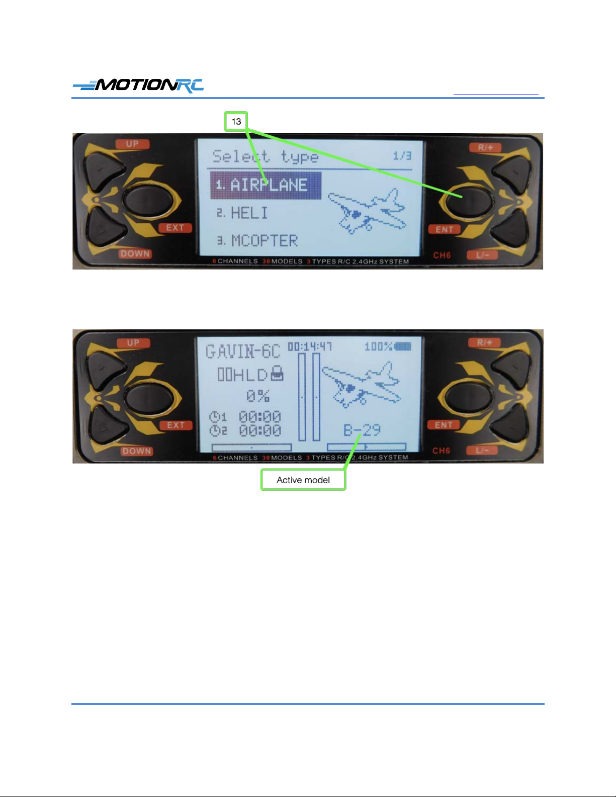
13. Hold the TRAINER switch in the forward position (toward the front of the transmitter)
and turn the transmitter on. You hear the bind tone on the transmitter and the Bind light
on the receiver becomes solid, indicating the bind process is complete.
14. Move the control associated with the servo you connected to ensure it moves. If so, the
model is bound. If not, repeat this process until it is successful.
15. Power off the receiver and remove the Bind plug (if applicable).
16. Power off the transmitter.
Prepare to Program an Airplane
1. Connect the ESC to the THRO channel on the receiver.
2. Connect the aileron, elevator, and rudder servos to their respective ports on the receiver.
3. Connect the retracts to the GEAR port.
4. Connect the flap servos to the AUX1 port.
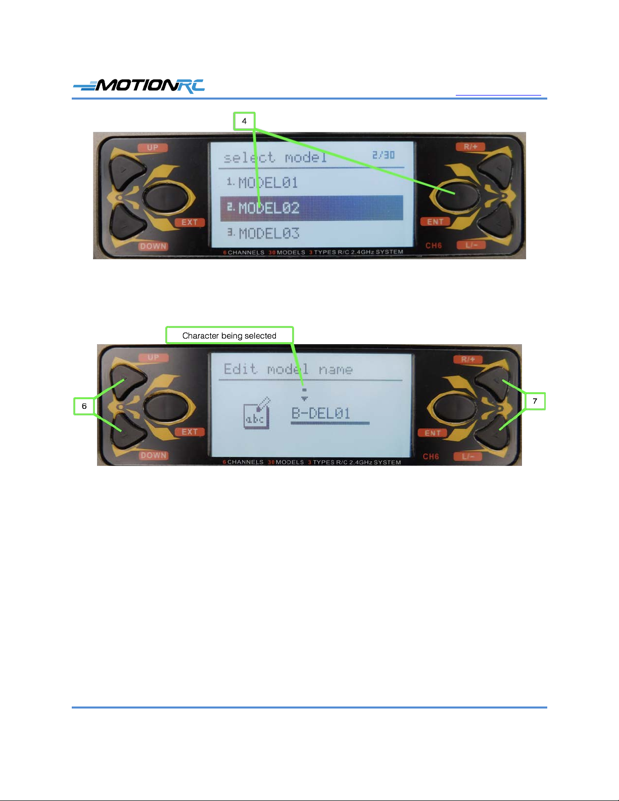
5. Turn the transmitter on and use steps 1-5 in the previous task to select the model you
want to program. Confirm that the model you want to program is shown.
6. Put the HOLD switch in the down position (toward the bottom of the transmitter); by
default, the throttle hold is active. Enabling the throttle hold before starting the model
prevents an unintended startup of the prop or EDF, which could be a safety hazard. When
the throttle hold is engaged, you see HLD on the home screen.
7. Connect a battery to the ESC. You should hear the startup tones from the ESC and see a
solid light on the receiver.
8. Check to make sure a spinning prop or EDF won’t be a safety hazard and move the
HOLD switch to the up position to enable the throttle.

www.motionrc.com
Motion RC Supplemental Guide for the Detrum GAVIN-6C Transmitter Page 7
9. Slowly advance the throttle until the motor driving the prop or EDF spins; when done,
move the throttle to the off position and re-engage the throttle hold by moving the HOLD
switch to the down position.
10. Systematically check each control surface for movement including rudder, ailerons,
elevator, flaps, and retracts. You can change direction and amount of movement later,
now you are ensuring the transmitter can activate the controls.
11. After you’ve confirmed all the model’s controls are working, you are ready to do the
detailed programming of the model.
If a plane has flaps, you usually want the flaps to be on a 3-position switch (up, takeoff,
and landing). If you connect the flap servos to the AUX1 channel, by default, they are
controlled by the FMOD switch, which is a 3-position switch. If you want the flaps to be
controlled by the FLAP switch, which only has two positions, use the Func Set screen to
set the FLAP switch to the AUX1 channel (this screen is used in the “Set Dual Rates”
task later in this guide).
Program Servo Direction
1. Set the correct direction for each servo using the Rev Set function; to access this from the
home screen, press ENT, select Model Parameter, press ENT, select Rev Set, and press
ENT. You move to the Rev Set screen where you see the current servo direction (Norm
or Rev) for each channel.
2. Check the direction of motion for a control surface, such as the elevator. If the direction
needs to be reversed, perform step 3; if not, skip to step 4.
3. Select the channel for the control surface (such as CH2 for the elevator), and press the
R/+ button. The direction setting changes from Norm to Rev and the servo moves in the
opposite direction.

www.motionrc.com
Motion RC Supplemental Guide for the Detrum GAVIN-6C Transmitter Page 8
4. Check the direction of motion for another control surface, such as the ailerons.
5. If the direction needs to be reversed, select the corresponding channel on the Rev Set
screen and press the R/+ button.
6. Repeat steps 3 and 4 until you are sure all the control surfaces move in the correct
direction.
7. When you’re done setting direction, press EXT three times.
Program Servo Range of Motion
1. Set the range of motion for each servo using the End Point function; from the home
screen, press ENT, select Model Parameter, press ENT, select End Point, and press
ENT. You move to the End Point screen where you see the current range for each
channel indicated by the LOW and HIG settings for each channel. LOW indicates the
negative side of the range while HIG indicates the positive side. Each range can be set
between 0 and 120.
2. Select the channel and range of motion you want to set, such as CH1 LOW.
3. Press R/+ to increase the range in that direction (the maximum is 120) or L/- to decrease
the range (the minimum is 0).
4. Select the other direction for the channel you selected in step 2, such as HIG.
5. Press R/+ to increase the range in that direction (the maximum is 120) or L/- to decrease
the range (the minimum is 0).
6. Repeat steps 2-5 until you have set the range of motion for all of the channels you are
using.
7. Press EXT three times to move back to the home screen.

www.motionrc.com
Motion RC Supplemental Guide for the Detrum GAVIN-6C Transmitter Page 9
Program Servo Sub Trim
1. Set the sub trim (position of the servo arm at the neutral position) for each servo using the
Sub Trim function; from the home screen, press ENT, select Model Parameter, press
ENT, select Sub Trim, and press ENT. You move to the Sub Trim screen where you see
the current sub trim (a value between -100 and 100) for each channel.
2. Select the channel for which you want to set sub trim, such as CH1.
3. Press the R/+ button to set the sub trim in the positive direction or L/- to set it in the
negative direction until the servo arm is where you want it to be when its control is in the
neutral position.
4. Repeat steps 2 and 3 until you have set the sub trim for all of the channels you are using.
5. When you’re done setting sub trims, press EXT three times.
Program Expo
Expo (short for Exponential) changes the relationship between movement of the control sticks
near their center positions and the corresponding movement of control surfaces. Without expo, a
control surface moves in direct proportion to a stick’s motion, i.e., if you move a stick 25% of its
range, the corresponding control surface also moves through 25% of its range. With expo
applied, the control surface does not move in linear proportion to stick movement; expo can be
positive or negative.
Positive expo means the control surface moves less with the same stick movement near its center
position, e.g., if you move the stick to 25% of its range, the control surface moves less than 25%
of its range. Positive expo makes a plane’s controls less sensitive to stick movements near the
center position, making the model less “twitchy” (meaning that it is overly sensitive). With
positive expo, the plane doesn’t react as quickly to stick movements near their centers, which is

www.motionrc.com
Motion RC Supplemental Guide for the Detrum GAVIN-6C Transmitter Page 10
the area you primarily use during “normal” flight (takeoffs, landings, basic turns, etc.). As you
move sticks further from their center positions, the control surfaces move exponentially more
and the plane reacts more quickly to further control inputs; this is the area you use when
performing aerobatics (when you want more control surface movement).
The more positive expo you apply, the larger is the range of motion of the sticks with less
sensitivity.
The amount of expo you should use depends on the model you are flying and your personal
preferences. You can often find suggested expo settings for a model in its manual. If not, you can
use some general guidelines as a starting point: for a high-wing trainer, expo settings between 10
and 20 are usually a good starting setting while for an aerobatic plane or EDF (jet), expo settings
of 30-40 are typical.
Negative expo increases the sensitivity of control surfaces to stick movement; negative expo is
typically used by advanced pilots to perform extreme maneuvers. Negative expo is not
recommended unless you are a very experienced pilot.
On the GAVIN-6C, you can set expo on each control surface (ailerons, elevator, and rudder). For
example, some models need more expo on the ailerons and less on the rudder.
1. To configure expo, from the home screen, press ENT, select Model Parameter, press
ENT, select Stick Curve, and press ENT. You move to the AIL Curve screen where you
set the relationship between the aileron stick movement on the transmitter and the aileron
servos.
2. Select EXP.
3. Press the R/+ button to increase the amount of expo or L/- to decrease it. As you apply
expo, the graph on the right side of the screen shows the amount of expo applied. (To
remove expo, select RESET and press R/+ or L/-.)

www.motionrc.com
Motion RC Supplemental Guide for the Detrum GAVIN-6C Transmitter Page 11
4. When you are done setting expo for the aileron channel, press ENT. You move to the
ELE Curve screen.
5. Repeat steps 2 and 3 to set expo for the elevator channel.
6. Press ENT. You move to the RUD Curve screen.
7. Repeat steps 2 and 3 to set expo for the rudder channel.
8. When you are done setting expo, press EXT three times to return to the home screen.
Program Dual Rates
The dual rates setting enables you to change the total amount a control surface moves when the
corresponding stick is moved through its maximum range. On the GAVIN-6C radio, you can
choose between 60% and 100%; when you flip the switch with which dual rates are controlled,
you toggle between these values. When the switch is in the 60% position, the corresponding
control surface moves through 60% of its maximum range of motion. When the switch is in the
100% position, the control surface moves through 100% of its range of motion.
You use dual rates to make control surfaces move less for the same amount of stick motion,
making the control less sensitive. For example, if a plane banks too much too quickly, you can
enable dual rates to make the ailerons move less for the same amount of stick movement.
Following are a couple of situations in which you might want to use dual rates:
• You’re flying a plane for the first time and aren’t sure how much control surface
movement you want to have. You can have the option of less control surface movement
in case you find the full control movement to be too much. You can flip the dual rate
switch to calm the plane down while you get used to it.
• You want to have two flight “modes.” You can use the lower rate setting (60%) when
you are just cruising around, during takeoff or landing, or at other times when you want
the plane to be less sensitive to your control inputs. When you are doing aerobatics or just
want more control, you can move into the higher rate (100%) setting.
The GAVIN-6C enables you to use the HOLD, FMOD, GEAR, or FLAP switches to activate
dual rates. You can enable or disable dual rates for the ailerons, elevators, and rudder channels
individually. And, you can put the dual rates for all channels on the same switch or use different
switches for each channel. (In most cases, you want to use the same switch for all channels to
keep things simpler.)
Because the FLAP switch is a two-position switch, it is useful for dual rates (if a model has flaps,
put them on the FMOD switch because it is a three-position switch).

www.motionrc.com
Motion RC Supplemental Guide for the Detrum GAVIN-6C Transmitter Page 12
1. To enable dual rates from the home screen, press ENT, select Model Set, press ENT,
select Func Set, and press ENT. You see the Func Set screen.
2. To activate dual rate for the aileron, select AIL D/R and press the R/+ key until the switch
you want to use to activate dual rates is shown. You can use the HOLD, FMOD, GEAR,
or FLAP switch to activate dual rates; choose OFF if you don’t want to use dual rates on
a channel. You can use a switch even if it already being used for another function. In
most cases, you want the dual rate switch to be used only for dual rates.
3. To activate dual rate for the elevator, select ELE D/R and press the R/+ key until the
switch you want to use to activate dual rates is shown or select OFF to disable it. You
can use the same switch for all dual rates, which is the most common configuration.
4. Repeat step 3 to enable dual rates for the rudder channel, if desired.
5. Press EXT three times to return to the home screen.
6. Make sure you know which direction of the switches you selected in steps 2, 3, and 4

www.motionrc.com
Motion RC Supplemental Guide for the Detrum GAVIN-6C Transmitter Page 13
activates the low and high rates; do this by powering up the receiver and holding a
control (such as the aileron stick) in its maximum position. Flip the switch on which you
set dual rates for that channel to see if the control surface moves to its maximum position
or moves to the 60% position. This tells you which position of the switch is high rates
and which is low rates. If you used different switches for different controls, make sure
you check each of them.
Set Timers
It’s a good idea to set timers so you know when you should land a model—before it runs the
LiPo flight pack battery down so far that the ESC shuts down or damages the battery. Typically,
you want the timer to start when you advance the throttle and stop when the throttle is off.
You can often find the suggested flight time for a specific battery capacity in the manual
provided with a model. If not, it can take some experimentation to determine the time you should
set for your model and the batteries you use. Start with a conservative value and test the battery
status when you are done with a flight. You can then increase or decrease the timer accordingly.
1. Set the timers using the Timer Set screens; from the home screen, press ENT, select
Model Set, press ENT, select Timer 1 Set, and press ENT.
2. Select Type and use the R/+ or L/- buttons to choose a setting for timer 1. OFF leaves the
timer inactive. Hidden leaves the timer active, but it doesn’t appear on the home screen
(it plays an alert when the timer expires). UP Timer causes the timer to count up. DOWN
Timer causes the timer to count down starting from a time you set.
3. If you selected OFF in step 2, skip to step 8.
4. Select Control SW and use the R/+ or L/- buttons to choose the control you want to
associate with the timer. The most common control is the THR (throttle) so that the timer
measures the amount of time the throttle is applied. You can also choose either position

www.motionrc.com
Motion RC Supplemental Guide for the Detrum GAVIN-6C Transmitter Page 14
of the HOLD switch, or two positions of the FMOD switch.
5. If you selected THR in step 4, select THR Position and use the R/+ or L/- buttons to set
the throttle position at which the timer starts; if you didn’t select THR, skip this step. The
default is -90, which starts the timer as soon as the throttle moves above the -90 position.
6. Select Timer (min) and use the R/+ or L/- buttons to set the minutes of time associated
with the timer.
7. Select (sec) and use the R/+ or L/- buttons to set the seconds of time associated with the
timer. For example, to have the timer start counting down from 5 minutes and 30
seconds, choose 5 in step 6 and 30 in step 7.
8. Press EXT to move back to the Model Set screen.
9. Select Timer 2 Set, and press ENT. You move to the Timer 2 Set screen.
10. Use steps 2-7 to configure timer 2. If you want to use only timer 1, set timer 2 to OFF.
11. When you’re done setting timer 2, press EXT three times to move back to the home
screen. You see the values you set for timers that aren’t hidden. The timers activate
according to your settings; for example, a timer associated with the throttle position runs
when the throttle is above the position set in step 5.
Perform a Range Test
1. You should perform a range test for any new model; to start the test, hold the ENT button
down and turn the transmitter on.
2. Connect the receiver to the battery and it binds to the transmitter. You see “Test mode
on” on the transmitter screen and its status light flashes.
3. Walk 30-50 feet from the model while activating controls to make sure the control
surfaces move when you move the associated transmitter controls.
4. If you can get at least 30 feet away from the model and still have control, it passes the
range test and is ready to fly. If not, you need to re-position the receiver or antennas and
repeat the range test until it passes.
5. Press EXT to exit the range test mode.
Table of contents
Other MotionRC Transmitter manuals