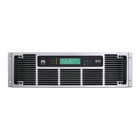
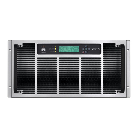
Nautel VS300 Programming manual

VS300 Transmitter
Troubleshooting Manual
Document:NHB-VS300-TRB
Issue: 6.0 2014-11-01
Status: Standard


Nautel Limited
10089 Peggy’s Cove Road
Hackett’s Cove, NS Canada B3Z 3J4
Phone: +1.902.823.3900 or
Toll Free: +1.877.6NAUTEL (6628835) (Canada & USA only)
Fax: +1.902.823.3183
Nautel Inc.
201 Target Industrial Circle
Bangor, Maine USA 04401
Phone: +1.207.947.8200
Fax: +1.207.947.3693
Customer Service (24 hour support)
+1.877.628.8353 (Canada & USA only)
+1.902.823.5100 (International)
Email: [email protected]
Web: www.nautel.com
The comparisons and other information provided in this document
have been prepared in good faith based on publicly available
information. The reader is encouraged to consult the respective
manufacturer's most recent published data for verification.
© Copyright 2014 NAUTEL. All rights reserved.


VS300 Troubleshooting Manual Table of contents
Page v
Contents
Release control record vii
Responding to alarms 1-1
Corrective maintenance 1-1
Electrostatic protection 1-3
Identifying an alarm 1-4
Troubleshooting tips 1-23
Replacing a suspect PWB, power supply or fan 1-24
PA PWB replacement 1-26
Pre-amp PWB replacement 1-28
Power Supply Module Replacement 1-30
+48 V Power Supply Replacement 1-31
LVPS Replacement 1-32
Cooling fan replacement 1-33
Exciter/Control PWB Replacement 1-35
PS Distribution PWB Replacement 1-38
Output power probe PWB replacement 1-39
Detailed Circuit Descriptions 2-1
Exciter/control PWB (NAPE87A) 2-1
PS distribution PWB (NAPS40) 2-2
Pre-amplifier PWB (NAPA27A) 2-3
Power amplifier PWB (NAPA23/03) 2-3
Parts Lists 3-1
Parts information 3-1
Family tree 3-1
How to locate information about a specific part 3-1

VS300 Troubleshooting Manual Table of contents
Page vi Issue 6.0 2014-11-01
Column content 3-2
OEM code to manufacturer’s cross-reference 3-3
Common abbreviations/acronyms 3-4
Wiring/connector lists 4-1
Wiring lists provided 4-1
Wiring lists not provided 4-1
Connector mating information 4-1
Wire colours 4-1
Printed wiring board patterns 4-1
Reading Electrical Schematics 5-1
Component values 5-1
Graphic symbols 5-1
Logic symbols 5-1
Reference designations 5-1
Unique symbols 5-2
Identifying schematic diagrams 5-2
Structure of schematics 5-2
Locating schematic diagram(s) for a functional block 5-3
Locating a part or assembly on a schematic 5-3
Mechanical Drawings 6-1
Identifying mechanical drawings 6-1
Content of mechanical drawings 6-1
Locating a part or assembly on a mechanical drawing 6-1
List of terms 7-1

VS300 Troubleshooting Manual
Issue 6.0 2014-11-01 Page vii
Release control record
Issue Date Reason
6.0 2014-11-01 Hardware Release 6 (NARF64E and NARF64E/01).
Supports software version VS SW 4.2

VS300 Troubleshooting Manual
Page viii Issue 6.0 2014-11-01

VS300 Troubleshooting Manual Responding to alarms
Issue 6.0 2014-11-01 Page 1-1
Section 1: Responding to alarms
This section provides instructions you need when performing troubleshooting on the VS300
transmitter. This section includes the following topics:
•Corrective maintenance
•Electrostatic protection - see page 1-3
•Identifying an alarm - see page 1-4
•Troubleshooting tips - see page 1-23
–AUI lockup - see page 1-23
•Replacing a suspect PWB, power supply or fan - see page 1-24
If none of the procedures and alarms described in this section address your problem, contact Nautel
for assistance. See “Technical support” on page ix.
Corrective maintenance
Corrective maintenance procedures consist of identifying and correcting defects or deficiencies that
arise during transmitter operation. Local and/or remote alarm signals are generated when a
malfunction occurs. If an alarm condition is caused by a malfunction in the RF power stage, the
transmitter may maintain operation at a reduced RF output level. The nature of the fault – and station
policy – will dictate whether an immediate maintenance response is necessary. Fault analysis and
rectification may be conducted from three different levels, with a different technical competence level
required for each: on-air troubleshooting, remote or local, and off-air troubleshooting.
On-air troubleshooting
On-air troubleshooting can be performed from a remote location, or locally at the transmitter site.
CAUTION:
The transmitter contains many solid state devices that may be damaged if
subjected to excessive heat or high voltage transients. Every effort must be taken
to ensure that circuits are not overdriven or disconnected from their loads while
turned on.

VS300 Troubleshooting Manual Responding to alarms
Page 1-2 Issue 6.0 2014-11-01
Remote troubleshooting
Remote on-air troubleshooting consists of monitoring the transmitter's radiated signal using an on-air
monitor or via a LAN connection, and observing the status of each remote fault alarm indicator.
Information obtained from these sources should enable an operator to decide whether an alarm
response may be deferred to a more convenient time, an immediate corrective action must be taken,
or if a standby transmitter must be enabled (if one is available). It is recommended that the
significance of remote indications, and the appropriate responses, be incorporated into a station's
standard operating procedures. Refer to “Identifying an alarm” on page 1-4 to determine the
remedial action required for a given fault.
Local troubleshooting
Local on-air troubleshooting consists of monitoring the transmitter's integral meters and fault alarm
indicators. Analysis of this data will normally identify the type of fault, and in most cases will
determine what corrective action must be taken. Refer to “Identifying an alarm” on page 1-4 to
determine the remedial action required for a given fault.
The power amplifier stage contains an integral modular reserve (IMR) feature. This feature permits
the transmitter to operate at a reduced RF output level when a malfunction occurs in one of its power
modules. Station operating procedures will dictate whether a reduced RF output level is acceptable.
When a reduced RF output level can be tolerated, replacement of the defective RF components may
be deferred to a convenient time.
Off-air troubleshooting
Off-air troubleshooting must be performed when routine on-air calibration adjustments will not
restore operation.
It is recommended that the transmitter’s output be connected to a precision 50 resistive dummy
load (rated for at least the maximum transmitter power rating of 330 W) before starting off-air
troubleshooting procedures. If an appropriate dummy load is not available, troubleshooting for a
majority of faults can be performed with the RF power stage turned off. The transmitter may remain
connected to its antenna system for these procedures.
CAUTION:
Reduce the RF output level to a minimal value when troubleshooting faults in the
transmitter. This is particularly important when the transmitter’s cover is
removed - where possible overheating could occur - or when the transmitter is
connected to the antenna system.
VS300 Troubleshooting Manual Responding to alarms
Issue 6.0 2014-11-01 Page 1-3
Electrostatic protection
The transmitter's assemblies contain semiconductor devices that are susceptible to damage from
electrostatic discharge. The following precautions must be observed when handling an assembly
which contains these devices.
Electrical discharging of personnel
Personnel should be electrically discharged by a suitable grounding system (e.g., anti-static mats,
grounding straps) when removing an assembly from the transmitter, and while handling the assembly
for maintenance procedures.
Handling/Storage
An assembly should be placed in an anti-static bag when it is not installed in a host transmitter, or
when it is not undergoing maintenance. Electronic components should be stored in anti-static
materials.
Tools/Test equipment
Testing and maintenance equipment – including soldering and unsoldering tools – should be suitable
(i.e., grounded tip) for contact with static sensitive semiconductor devices.
Stress current protection
Every precaution should be taken to ensure the static sensitive semiconductor devices are protected
from unnecessary stress current. This is achieved by ensuring that current is not flowing when an
electrical connection is broken, and that voltages are not present on external control/monitoring
circuits when they are connected.
CAUTION:
Electrostatic energy is produced when two insulating materials are rubbed
together. A person wearing rubber-soled shoes, walking across a nylon carpet or a
waxed floor, can generate an extremely large electrostatic charge. This effect is
magnified during periods of low humidity. Semiconductor devices such as
integrated circuits, field-effect transistors, thyristors and Schottky diodes may be
damaged by this high voltage unless adequate precautions are taken.

VS300 Troubleshooting Manual Responding to alarms
Page 1-4 Issue 6.0 2014-11-01
Identifying an alarm
You can identify an alarm locally by viewing the front panel (see “Front panel alarm checks”) or
remotely by viewing the AUI’s Transmitter Status page (see “AUI Transmitter status page checks”
on page 1-6).
Front panel alarm checks
There two ways to check for alarms on the front panel:
•Alarm/status LEDs
•View alarms screen - see page 1-5
Alarm/status LEDs
There are four LEDs on the left-hand side of the LCD display that provide information about the
operational status of various sections of the transmitter - Exciter, Power Amplifier, Output Network
and Power Supply (see Figure 1.1). The LEDs can glow green, amber or red. Typically, green
indicates normal operation, amber indicates a warning, and red indicates a fault or error.
Figure 1.1: Alarm/Status LEDs
When an LED is:
• green - transmitter is on, with no known faults.
• amber - a fault is present that may cause a reduction in RF power, but the transmitter is still
producing RF power.
• red - a fault is present and the transmitter is not producing RF power.
When a fault is present, the transmitter may still produce an RF output. In this case, or if the
transmitter has shut down, you should schedule and commence more in-depth fault diagnosis. See
“View alarms screen” on page 1-5.
Exciter
Power Amplifier
Output Network
Power Supply

VS300 Troubleshooting Manual Responding to alarms
Issue 6.0 2014-11-01 Page 1-5
View alarms screen
If an alarm exists and is currently being recognized by the transmitter system, it is displayed in the
View Alarms screen (Main Menu -> View Status -> View Alarms) of the front panel Display (see
Figure 1.2).
Figure 1.2: View Alarms Screen
Table 1.1 on page 1-8 contains a column for most alarms that can occur, sorted alphanumerically.
The Description and Troubleshooting Action column provides a brief description of the alarm,
troubleshooting tips and a cross-reference to more detailed troubleshooting, if applicable.
1. Scroll through the View Alarms screen to view the active faults.
2. Attempt to clear any latching alarms by pressing the checkmark button in the Main Menu ->
Reset Alarms screen. If the alarm persists, it will not clear from the display.
3. Locate the alarm name in Table 1.1 on page 1-8 to determine the cause of the alarm and
perform any recommended procedures in the Description and Troubleshooting Action
column. This may also lead to replacing a suspect PWB, power supply or fan, as detailed in
“Replacing a suspect PWB, power supply or fan” on page 1-24.
4. If troubleshooting and subsequent replacement of a suspect PWB or module causes the
alarm to disappear from the View Alarms screen, the alarm has been successfully cleared. If
the alarm does not remove the fault condition, contact Nautel.
NOTE:
Before undertaking any troubleshooting, record all meter readings and note if any other alarms
are displayed on the View Alarms page. Record all alarms.
NOTE:
Table 1.1 on page 1-8 contains a column for most Alarms that can occur, sorted
alphanumerically for each sub-system, including both the names displayed on the AUI and, if
different, the front panel UI (in parentheses).
The Description and Troubleshooting Action column provides a brief description of the
alarm, troubleshooting tips and a cross-reference to more detailed troubleshooting, as applicable.

VS300 Troubleshooting Manual Responding to alarms
Page 1-6 Issue 6.0 2014-11-01
AUI Transmitter status page checks
If an alarm exists and is being recognized by the transmitter, it is displayed under the Alarms tab of
the transmitter status page (see Figure 1.3). The Device name indicates the sub-system origin of the
alarm. The sub-systems that can be displayed are:
– Controller: All alarms in this sub-system apply to the controller.
– Exciter: All alarms in this sub-system apply to the exciter.
Figure 1.3: Transmitter Status Page
1. If an alarm exists, the Status button at the bottom of the AUI display will be red. Click the
Status button to go to the Transmitter Status page (see Figure 1.3). View the list of active
faults by pressing the Alarms tab. Alarms are listed by their origin (Device column), then by
name (Alarm column), and then by severity [1 = low (RF output not affected), 5 = medium
(RF output is reduced), 10 = high (RF output is inhibited); see Level column].
2. Attempt to clear any latching alarms by pressing the Reset button on the bottom banner of
the page. If the alarm persists, it will not be cleared from the display.

VS300 Troubleshooting Manual Responding to alarms
Issue 6.0 2014-11-01 Page 1-7
3. Locate the alarm name in Table 1.1 on page 1-8 to determine the cause of the alarm and
perform any recommended procedures in the Description and Troubleshooting Action
column. This may also lead to replacing a suspect PWB, power supply or fan, as detailed in
“Replacing a suspect PWB, power supply or fan” on page 1-24.
4. If troubleshooting and subsequent replacement of a suspect PWB or module causes the
alarm to disappear from the Transmitter Status page, the alarm has been successfully
cleared. If the fault condition does not clear, contact Nautel.
.
NOTE:
Table 1.1 on page 1-8 contains a column for most Alarms that can occur, sorted
alphanumerically for each sub-system, including both the names displayed on the AUI and, if
different, the front panel UI (in parentheses).
The Description and Troubleshooting Action column provides a brief description of the
alarm, troubleshooting tips and a cross-reference to more detailed troubleshooting, as applicable.
NOTE:
Before undertaking any troubleshooting, record all AUI meter readings and note if any other
alarms are displayed on the Transmitter Status page. Record all alarms. The most
convenient way to do this is by using a web browser over a LAN connection to save screen shots
of critical status, meter and alarm pages. From the System Review page, press the
information (!)button for each sub-device (Controller and Exciter) to view (and save) detailed
information (see “Viewing real-time meters” on page 2-36 of the Operations and Maintenance
Manual).

VS300 Troubleshooting Manual Responding to alarms
Page 1-8 Issue 6.0 2014-11-01
Table 1.1: Troubleshooting Alarms
Alarm Name
AUI and
(Front Panel)
Front Panel
LED (color) Description and Troubleshooting Action
+1.2V Supply
Fail
(+1.2V Fail)
PS (red) This alarm occurs if the +1.2 V supply on the exciter/control PWB
(A1) is outside of its acceptable voltage range (between +1.1 V
and +1.3 V). The VS300 takes no action on this alarm. Check for a
+5V Supply Fail alarm: If present, follow the associated
troubleshooting procedure. If not present, use a digital multimeter
to measure between TP5 (+1.2 V) and TP6 (ground) of the
exciter/control PWB. If the measured value is within the
acceptable range, suspect the sampling circuitry on the exciter/
control PWB (A1). If not, use a digital multimeter to measure
between TP7 and TP6 (ground). The measured voltage should be
between +4.5 V and +5.5 V. If the measured voltage is within the
acceptable range, the power supply circuitry on the exciter/control
PWB has failed. Replace the exciter/control PWB (see “Exciter/
Control PWB Replacement” on page 1-35). If not, check ribbon
cable W4 for damage, and verify connectors W4P1 and W4P2 are
properly seated in A2J3 and A1J11 respectively. If there are no
visible problems with the ribbon cable, contact Nautel for further
support.
+1.8V Supply
Fail
(+1.8V Fail)
PS (red) This alarm occurs if the +1.8 V supply on the exciter/control PWB
(A1) is outside of its acceptable voltage range (between +1.6 V
and +2.0 V). The VS300 takes no action on this alarm. Check for a
+3.3V Supply Fail alarm: If present, follow the associated
troubleshooting procedure. If not present, use a digital multimeter
to measure between TP4 and TP6 of the exciter/control PWB. If
the measured value is within the acceptable range, suspect the
sampling circuitry on the exciter/control PWB. If not, the power
supply circuitry has failed on the exciter/control PWB. If
necessary, replace the exciter/control PWB (see “Exciter/Control
PWB Replacement” on page 1-35).

VS300 Troubleshooting Manual Responding to alarms
Issue 6.0 2014-11-01 Page 1-9
+15V Supply
Fail
(+15V Fail)
PS (green/
amber) This alarm occurs if the +15 V output of the low voltage power
supply (LVPS) (U3) is outside of its acceptable voltage range
(between +13.5 V and +16.5 V). Use a digital multimeter to
measure between +V2 and COM of the LVPS. If the measured
value is not within the acceptable range, replace the LVPS (see
“LVPS Replacement” on page 1-32). If the measured value is
within the acceptable range, use a digital mutimeter to measure
the voltage between TP11 (+15 V) and TP7 (ground) of the PS
distribution PWB (A2). If the measured value is not within the
acceptable range, turn off ac power and use a digital multimeter to
perform a continuity check across fuse F1 of the PS distribution
PWB. If the measurement is greater than 1 , replace F1 (Nautel
Part # FA58 in the ancillary kit), restore ac power and check the
alarm again. If the measurement is less than 1 , or replacing F1
does not clear the alarm, suspect the connection between the
+48 V power supply and the PS distribution PWB, and contact
Nautel for further assistance. If the measured value is within the
acceptable range, check ribbon cable W2 for damage and that
W2P1 and W2P2 are properly seated in A1J12 and A2J2
respectively. If there are no visible problems with the ribbon cable,
suspect the sampling circuitry on the PS distribution PWB. If
necessary, replace the PS distribution PWB (see “PS Distribution
PWB Replacement” on page 1-38) . If the alarm persists after
replacing the PS distribution PWB, suspect the exciter/control
PWB (A1).
-15V Supply
Fail
(-15V Fail)
PS (amber) This alarm occurs if the -15 V supply on exciter/control PWB (A1)
is outside of its acceptable voltage range (between -13.5 V and
-16.5 V). The VS300 takes no action on this alarm. Check for a
+15V Supply Fail alarm: If present, follow the associated
troubleshooting procedure. If not present, use a digital multimeter
to measure between TP13 and TP11 (ground) of the exciter/
control PWB. If the measured value is within the acceptable
range, suspect the sampling circuitry on the exciter/control PWB.
If not, use a digital multimeter to measure between TP2 and TP6
(ground). The measured voltage should be between +13.5 V and
+16.5 V. If the measured voltage is within the acceptable range,
the power supply circuitry on the exciter/control PWB has failed.
Replace the exciter/control PWB (see “Exciter/Control PWB
Replacement” on page 1-35). If not, check ribbon cable W4 for
damage and that connectors W4P1 and W4P2 are properly
seated in A2J3 and A1J11 respectively. If there are no visible
problems with the ribbon cable, contact Nautel for further support.
Alarm Name
AUI and
(Front Panel)
Front Panel
LED (color) Description and Troubleshooting Action

VS300 Troubleshooting Manual Responding to alarms
Page 1-10 Issue 6.0 2014-11-01
+3.3V Supply
Fail
(+3.3V Fail)
PS (red) This alarm occurs if the +3.3 V supply on the exciter/control PWB
(A1) is outside of its acceptable voltage range (between +3.0 V
and +3.6 V). The VS300 takes no action on this alarm. Check for a
+5V Supply Fail alarm: If present, follow the associated
troubleshooting procedure. If not present, use a digital multimeter
to measure between TP3 (+3.3 V) and TP6 (ground) of the
exciter/control PWB. If the measured value is within the
acceptable range, suspect the sampling circuitry on the exciter/
control PWB. If not, use a digital multimeter to measure between
TP7 and TP6 (ground). The measured voltage should be between
+4.5 V and +5.5 V. If the measured voltage is within the
acceptable range, the power supply circuitry on the exciter/control
PWB has failed. Replace the exciter/control PWB (see “Exciter/
Control PWB Replacement” on page 1-35). If not, check ribbon
cable W4 for damage and that connectors W4P1 and W4P2 are
properly seated in A2J3 and A1J11 respectively. If there are no
visible problems with the ribbon cable, contact Nautel for further
support.
+5V Supply
Fail
(+5V Fail)
PS (red) This alarm occurs if the +5 V output of the low voltage power
supply (LVPS) (U3) is outside of its acceptable voltage range
(between +4.5 V and +5.5 V). Use a digital multimeter to measure
between +5V and COM of the LVPS. If the measured value is not
within the acceptable range, replace the LVPS (see “LVPS
Replacement” on page 1-32). If the measured value is within the
acceptable range, use a digital mutimeter to measure the voltage
between TP12 (+5 V) and TP7 (ground) of the PS distribution
PWB (A2). If the measured value is not within the acceptable
range, turn off ac power and use a digital multimeter to perform a
continuity check across fuse F2 of the PS distribution PWB. If the
measurement is greater than 1 , replace F2 (Nautel Part # FA57
in the ancillary kit), restore ac power and check the alarm again. If
the measurement is less than 1 , or replacing F2 does not clear
the alarm, suspect the connection between the +48 V power
supply and the PS distribution PWB, and contact Nautel for further
assistance. If the measured value is within the acceptable range,
check ribbon cable W2 for damage and that W2P1 and W2P2 are
properly seated in A1J12 and A2J2 respectively. If there are no
visible problems with the ribbon cable, suspect the sampling
circuitry on the PS distribution PWB. If necessary, replace the PS
distribution PWB (see “PS Distribution PWB Replacement” on
page 1-38) . If the alarm persists after replacing the PS
distribution PWB, suspect the exciter/control PWB (A1).
Alarm Name
AUI and
(Front Panel)
Front Panel
LED (color) Description and Troubleshooting Action

VS300 Troubleshooting Manual Responding to alarms
Issue 6.0 2014-11-01 Page 1-11
AC Summary - Not displayed in AUI or UI status. This alarm occurs if there are
any ac input related alarms present. Check for other specific ac
fault alarms.
All Power
Amplifiers
Inactive
(All PAs
Inactive)
PA (red) This alarm indicates that the PA, pre-amp or the power supply
module has failed; therefore a PA failure alarm or power supply
module related alarms should also be present. If there are power
supply module or pre-amp related alarms present, follow the
associated troubleshooting procedure. If there are no power
supply module related alarms, perform the “PA resistance checks”
on page 1-27.If there is no problem found with the PA, or the
alarm still persists after replacing the damaged PA, suspect the
PS distribution PWB (A2).
Analog Left
Low
(Anlg Left Aud
Low)
Exciter (amber) This alarm indicates the analog left audio input level is too low or
is not applied. The VS300 takes no action on this alarm.
Analog Right
Low
(Anlg Right
Aud Low)
Exciter (amber) This alarm indicates the analog right audio input level is too low or
is not applied. The VS300 takes no action on this alarm.
ARM Network
Down Exciter (amber) This alarm indicates that the microcontroller that runs the remote
interfacing applications (ARM) is unable to aquire an IP address.
When this alarm is present, it will not be possible to access any of
the remote functionality. Check that the Ethernet cable is properly
connected to A1J8A on the rear of the transmitter. If the alarm is
still present see “Network setup” on page 2-72 of the Operations
and Maintenance Manuals for information on setting up the
network connection. Disable the alarm by setting DHCP to OFF
and setting the IP Address to all zeroes (i.e. 0.0.0.0).
ARM Not
Booted Exciter (amber) This alarm indicates that the microcontroller that runs the remote
interfacing applications (ARM) is not yet running. This alarm
should only be present when the transmitter is first turned on or
after the transmitter's ac power has been cycled.
Alarm Name
AUI and
(Front Panel)
Front Panel
LED (color) Description and Troubleshooting Action

VS300 Troubleshooting Manual Responding to alarms
Page 1-12 Issue 6.0 2014-11-01
ARM Not
Responding Exciter (amber) This alarm indicates that the microcontroller that runs the remote
interfacing applications (ARM) is not communicating with the
transmitter’s primary microcontroller (DSP). If the watchdog
function is enabled, the DSP will automatically reset the ARM. If
this alarm persists for more than 10 minutes, try cycling power
(off, then on) to the transmitter. If the alarm persists, replace the
exciter/control PWB (A1) if necessary (see “Exciter/Control PWB
Replacement” on page 1-35).
Audio Loss Exciter (red) This alarm, enabled by the user, indicates that the exciter’s audio
modulation level is below the level specified in the dead air
settings of the active preset (see “Audio Loss” on page 2-61 of the
Operations and Maintenance Manuals to enable/disable this
alarm and to configure the resulting action). Depending on the
setting, this alarm could trigger a preset change, inhibit RF or
have no effect (alarm only). Check the appropriate program
input(s) and the dead air setting for the preset.
Audio Loss
Summary Exciter (red) Not displayed in AUI or UI status. This alarm occurs if there are
any audio loss alarms present. Check for specific audio loss
alarms and troubleshoot accordingly. Ensure the preset audio
settings agree with the audio being applied to the exciter.
Audio
Processor
Offline
Exciter (amber) This alarm occurs if the exciter is configured to include an Orban
Inside audio processor, but it is not communicating with the
processor on the internal serial bus. Check all connections to the
Orban Inside audio processor card.
Audio
Shutdown Exciter (red) This alarm occurs if the exciter’s audio processing and FM
modulation code is shut down. Should display only during a
software upgrade.
Composite Low
(MPX Aud
Low)
Exciter (amber) This alarm indicates the composite audio input level is too low.
The VS300 takes no action on this alarm.
CPLD Version
Mismatch
(CPLD Ver
Mismatch)
Exciter (red) This alarm indicates that the CPLD version installed on the
transmitter does not match the version expected to be seen by the
version of code installed on the DSP. The VS300 will not be able
to turn RF on. Contact Nautel for further assistance.
Alarm Name
AUI and
(Front Panel)
Front Panel
LED (color) Description and Troubleshooting Action
Other manuals for VS300
5
Table of contents
Other Nautel Transmitter manuals

Nautel
Nautel VX150 Manual

Nautel
Nautel ND500II Manual

Nautel
Nautel VX150 User manual

Nautel
Nautel NV Series Technical manual

Nautel
Nautel NX50 User manual

Nautel
Nautel VS300 User manual

Nautel
Nautel Vector-LP VR125 Owner's manual

Nautel
Nautel VS1 User manual

Nautel
Nautel VS2.5 Programming manual

Nautel
Nautel XR6 User manual

Nautel
Nautel NX50 Programming manual

Nautel
Nautel XR12 Programming manual

Nautel
Nautel NX5 AM User manual

Nautel
Nautel NX100 User manual

Nautel
Nautel VX150 Manual

Nautel
Nautel FM10011 User manual

Nautel
Nautel NX50 User manual

Nautel
Nautel NV5LT Programming manual

Nautel
Nautel XR12 User manual

Nautel
Nautel XR12 User manual