9
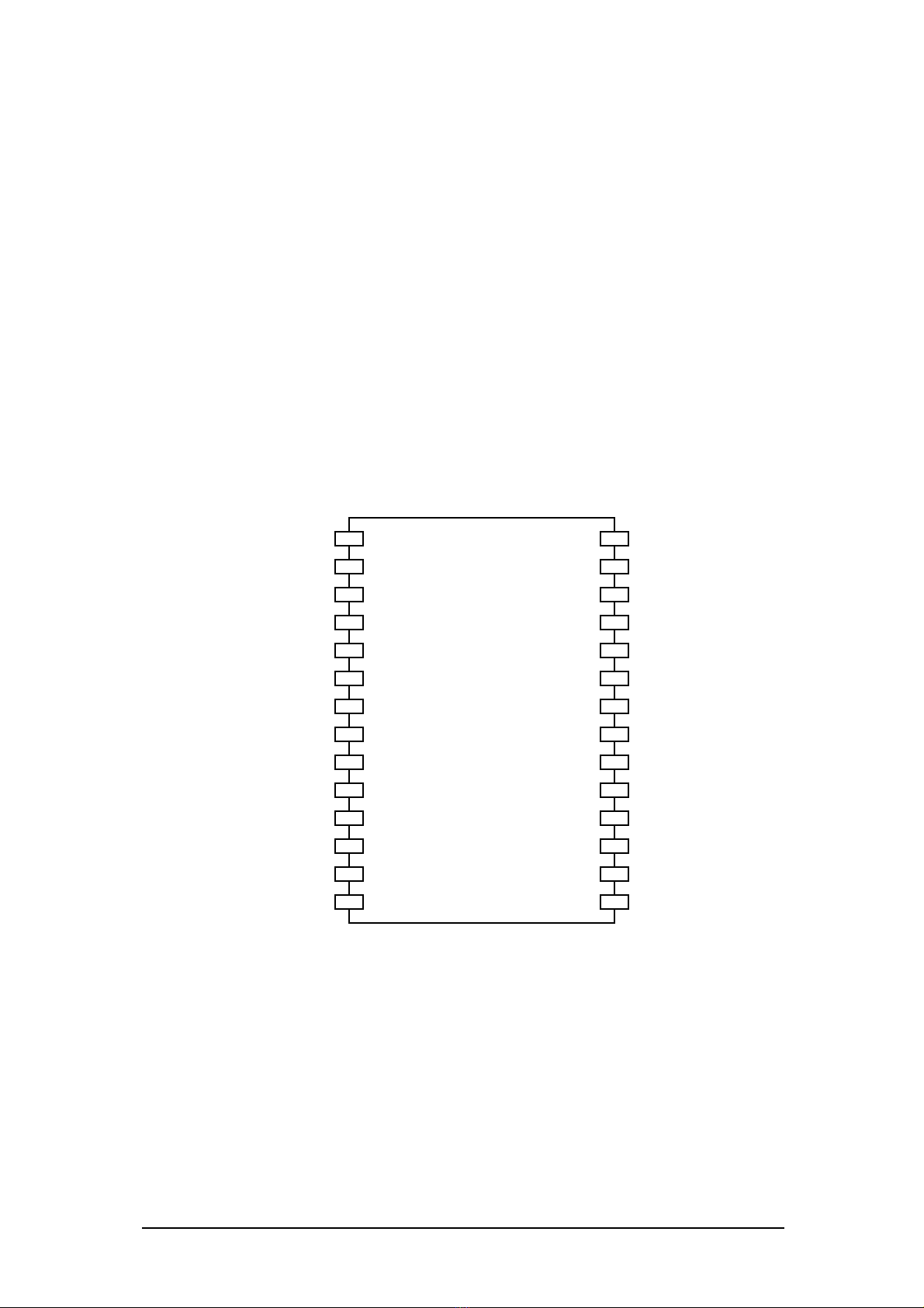
Pins Pin Name Type
1
I/O Level
23
Function
1 +5V P - +5V supply
2 A-CHA I FT Axis A encoder input CHA
3 A-CHB I FT Axis A encoder input CHB
4 A-HM I FT,AL Axis A home indicator input
5 A-FL I FT,AL Axis A forward limit input
6 A-RL I FT,AL Axis A reverse limit input
7 A-DIR O FT Axis A direction output
8 A-PWM O FT Axis A PWM output
9 STEPPER A I FT,AL Axis A Stepper select
10 STEPPER B I FT,AL Axis A Stepper select
11 Reserved - - Reserved. Do not use.
12 Reserved - - Reserved. Do not use.
13 Reserved - - Reserved. Do not use.
14 Gnd P - Ground
15 Gnd P - Ground
16 Reserved - - Reserved. Do not use.
17 Reserved - - Reserved. Do not use.
18 Reserved - - Reserved. Do not use.
19 Rx - - UART Receive
20 Tx - - UART Transmit
21 B-PWM O FT Axis B PWM output
22 B-DIR O FT Axis B direction output
23 B-RL I FT,AL Axis B reverse limit input
24 B-FL I FT,AL Axis B forward limit input
25 B-HM I FT,AL Axis B home indicator input
26 B-CHB I FT Axis B encoder input CHB
27 B-CHA I FT Axis B encoder input CHA
28 +5V P - +5V supply
Table 1 – MK-200 pin definitions
1
P = Power, I = Input, O = Output
2
FT = Five voltage Tolerant
3
AL = Active Low