4
INTRODUCTION SAFETY INFORMATION
PERSONAL SAFETY INSTRUCTIONS
•It is the owner’s and/or operator’s
responsibility to read and understand all
WARNINGS and operating instructions
contained on the product labels and within
the instruction manual prior to operation of
this product.
•It is also the owner’s and/or operator’s
responsibility to periodically inspect and
maintain this product and its labels. Read
the product labels and instruction manual
prior to operation of this product.
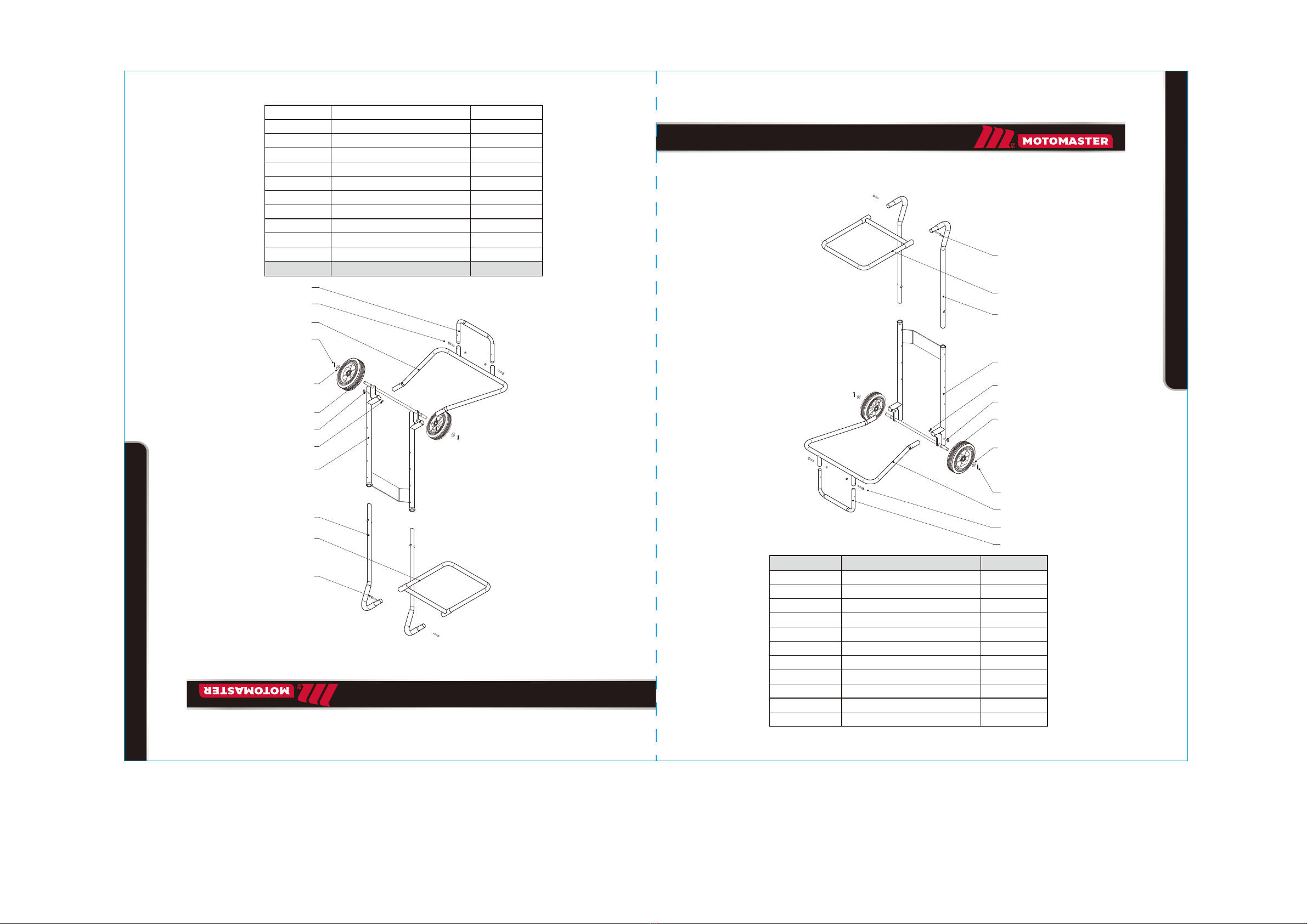
TECHNICAL SPECIFICATIONS
Model 009-1539-6
Capacity 300 lb (136 kg)
Tools for assembly
(Not included)
1. Adjustable wrench
2. Hex key (5mm)
3. Pliers
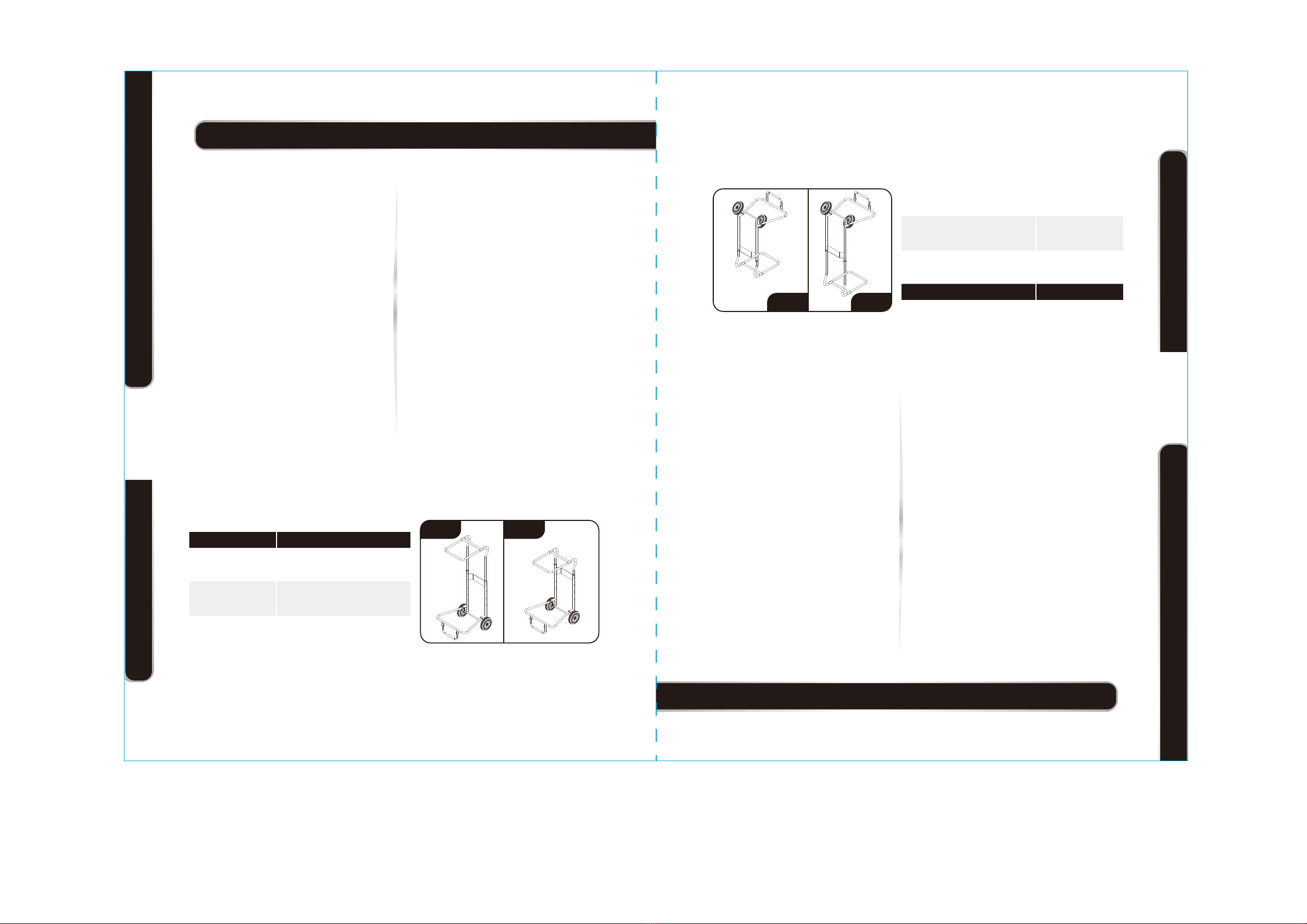
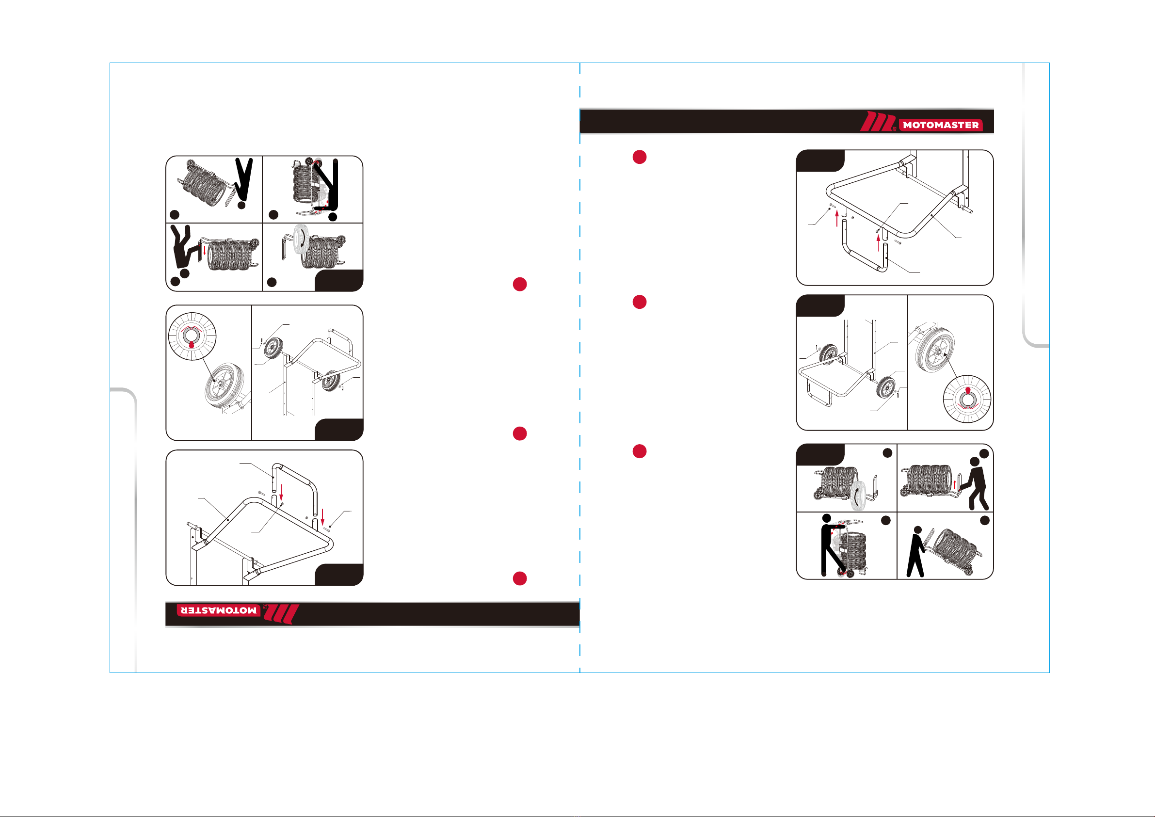
Adjustable storage
height:
Max: 57 13/64" (145.3 cm)
Min: 42 13/64" (107.2 cm)
TECHNICAL SPECIFICATIONS SAFETY INFORMATION
model no. 009-1539-6 | contact us 1-888-942-6686
The MotoMaster Tire Dolly is perfect for
storing and transporting tires. The capacity
of the tire dolly is 300 lb (136 kg).
®• When lifting or moving loaded dolly, take
care to prevent tires from tipping over.
• Do not modify the product.
• Do not use this product for purpose for which
it is not designed.
• When adjusting the height, ensure spring
buttons are fully engaged.
• Periodically check that all hardware is tight
and secure. Discontinue use if missing parts
or damaged.
• Not for use by children.
• Recommended for use on flat, level, hard
surface only. Wheels may scratch or dig into
less durable surfaces (such as linoleum or
wood).
• Do not discard this manual.
MAX MIN
4
INTRODUCTION CONSIGNES DE SÉCURITÉ
CONSIGNES DE SÉCURITÉ PERSONNELLE
•Il incombe au propriétaire et/ou à
l’utilisateur de lire et de comprendre tous
les AVERTISSEMENTS et instructions
contenus sur les étiquettes et dans le guide
d’utilisation avant d’utiliser cet article.
•Il incombe également au propriétaire et/ou
à l’utilisateur d’inspecter périodiquement
et d’entretenir cet article et ses étiquettes.
Lisez les étiquettes et le guide d’utilisation
avant d’utiliser cet article.
FICHE TECHNIQUE
Modèle 009-1539-6
Capacité 300 lb (136 kg)
Outils d’assemblage
(non compris)
1. Clé à molette
2. Clé hexagonale (5 mm)
3. Pince
Hauteur de
rangement réglable
Max : 57 13/64 po (145,3 cm)
Min : 42 13/64 po (107,2 cm)
FICHE TECHNIQUE CONSIGNES DE SÉCURITÉ
Nº de modèle : 009-1539-6 | Contactez-nous au 1 888 942-6686
Le chariot à pneus MotoMasterMD est parfait
pour ranger et transporter les pneus. La capacité
du chariot à pneus est de 300 lb (136 kg).
• Lorsque vous soulevez ou déplacez un chariot
chargé, veillez à empêcher les pneus de basculer.
• Ne modifiez pas l’article.
• N’utilisez pas cet article à des fins pour lesquelles
il n’a pas été conçu.
• Lors du réglage de la hauteur, assurez-vous que
les boutons à ressort sont complètement
enclenchés.
• Tous éléments de fixation doivent être vérifiés et
serrés régulièrement. Cessez d'utiliser cet article
si des pièces sont manquantes ou endommagées.
• Cet article ne doit pas être utilisé par des enfants.
• Recommandé pour une utilisation sur une surface
plane et dure seulement. Les roues peuvent rayer
ou creuser des surfaces moins dures (comme le
linoléum ou le bois).
• Ne jetez pas ce manuel.
MAX MIN