Motomaster Eliminator User manual

SAVE THESE INSTRUCTIONS!
This manual contains important safety and operating instructions. Read all instructions and follow
them with use of this product.
Questions? Call Customer Service Hotline: 1-877-466-8191
TABLE OF CONTENTS
TECHNICAL SPECIFICATIONS ............................................................................................ 3
SAFETY INFORMATION .....................................................................................................4
KEY PARTS DIAGRAM........................................................................................................7
INTENDED USE.................................................................................................................. 9
Options for connecting devices to the power inverter............................................... 9
OPERATION..................................................................................................................... 10
Determining the maximum load of connected devices........................................... 10
Wattage of commonly used devices........................................................................ 11
Before you start ...................................................................................................... 13
Connecting the MotoMaster® Eliminator® Mobile Power Outlet ............................. 14
Connecting the connector cables to the power inverter.......................................... 14
Connecting the inverter to a lighter socket (loads under 100W)............................. 16
Connecting the inverter to a 12V vehicle battery (loads up to 300 W) .................... 16
Safety guidelines for handling batteries .................................................................17
Switching on/o..................................................................................................... 19
Using the USB port .................................................................................................20
Automatic safety features....................................................................................... 21
MAINTENANCE ...............................................................................................................22
Maintaining battery condition................................................................................ 22
Fuse replacement.................................................................................................... 23
TROUBLESHOOTING .......................................................................................................24
WARRANTY ....................................................................................................................26
011-1870-6
300 W Mobile Power Outlet
PRODUCT MANUAL
011-1870-6-Mobile-Power-Outlet_300W-EN-07.indd 1-2 12/13/12 7:22 PM

43 Product Number 011-1870-6
AC POWER
AC output voltage (nominal) 115 V, 60 Hz
Maximum AC output power 300 W
Continuous power 240 W
Maximum AC output surge power 480 W
AC output frequency 60 ± 1 Hz
AC output waveform Modied sine wave
DC POWER
USB output 5 V / 2.1 A
No load current draw (at 12 V) < 0.3 A
Eciency (maximum) 85%
Low-voltage shutdown 10.0–11.0 V
High-voltage shutdown 15.0–16.3 V
PHYSICAL SPECIFICATIONS
Ambient operating temperature range 0 to 40 °C (32 to 104 °F)
Dimensions (L x W x H) 7/ x 3/ x 2”(187 x 100 x 50 mm)
Weight 1 lb 3 oz (550 g)
This manual contains information that relates to PROTECTING PERSONAL
SAFETY and PREVENTING EQUIPMENT PROBLEMS. It is very important to read
this manual carefully and understand it thoroughly before using the product.
The symbols listed below are used to indicate this information.
DANGER!
Potential hazard that will result in serious injury or loss of life.
WARNING!
Potential hazard that could result in serious injury or loss of life.
CAUTION!
Potential hazard that may result in moderate injury or damage to equipment.
IMPORTANT!
Installation, operation, or maintenance information that is important but not hazard
related.
TECHNICAL SPECIFICATIONS
SAFETY INFORMATION
011-1870-6-Mobile-Power-Outlet_300W-EN-07.indd 3-4 12/13/12 7:22 PM

65 WARNING!
• HEATED SURFACE. The power inverter housing may become uncomfortably warm, and can
reach up to 60 °C (140 °F) under extended high power operation.
• Do not use the inverter in a vehicle in which the plus pole of the car battery is connected to
the chassis! Before using the device, please determine how the battery is connected in the
respective vehicle.
• Do not operate the inverter if it has been dropped or damaged in any way.
• Always disconnect the device by pulling on the plug itself, not the power cable.
• The device must be fastened so that it does not cause a safety hazard in case of collision or
hard braking.
• Route the power cable so that it does not interfere with the driver of the vehicle when
plugged into the cigarette lighter socket.
• Prevent the power supply cable from coming into contact with hot parts of the engine or
from hanging over sharp edges and make sure it will not get caught on moving parts of the
engine.
• When using car batteries, always follow the advice from the manufacturer of the battery and
in the vehicle instruction manual.
• Using improper voltage may result in damage to the device and possible injury to the user.
The correct voltage is listed on the rating plate.
• Never leave the device unattended during operation.
CAUTION!
• Do not connect live AC power to the power inverter’s AC outlets.The inverter will be damaged
even if it is switched o.
• Avoid placing the inverter on or near heating vents, radiators or other sources of heat. Do not
place the inverter in direct sunlight (e.g. on the vehicle's dashboard) in order to prevent an
overheat shutdown caused by high temperatures. Do not use the inverter in temperatures
over 40 °C (104 °F).
CAUTION!
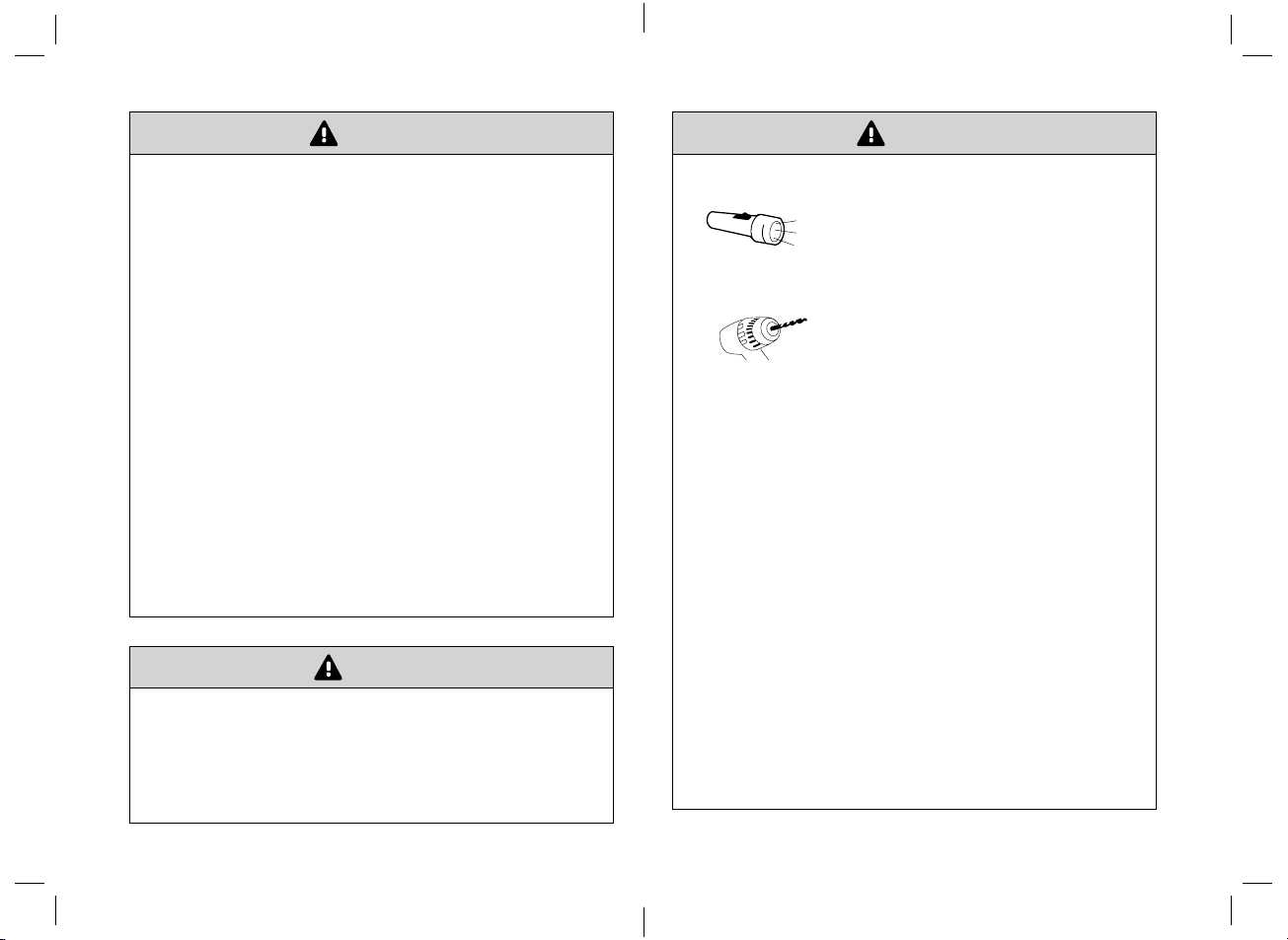
• DO NOT USE the power inverter with the following equipment:
Small battery-operated devices such as rechargeable ashlights,
some rechargeable shavers, and night lights that are plugged
directly into an AC receptacle to recharge.The device can be
damaged if connected to the power inverter. Always recharge
batteries using a separate battery charger.
Battery chargers used in power tools. These chargers display a
WARNING LABEL stating that there are dangerous voltages at the
charger’s battery terminals.
• Do not insert foreign objects into the power inverter outlets or ventilation openings.
• The power inverter must only be connected to a battery that has a nominal output of 12V. It
will not operate if connected to a 6V battery and may be damaged if connected to a battery
with 16 V or more.
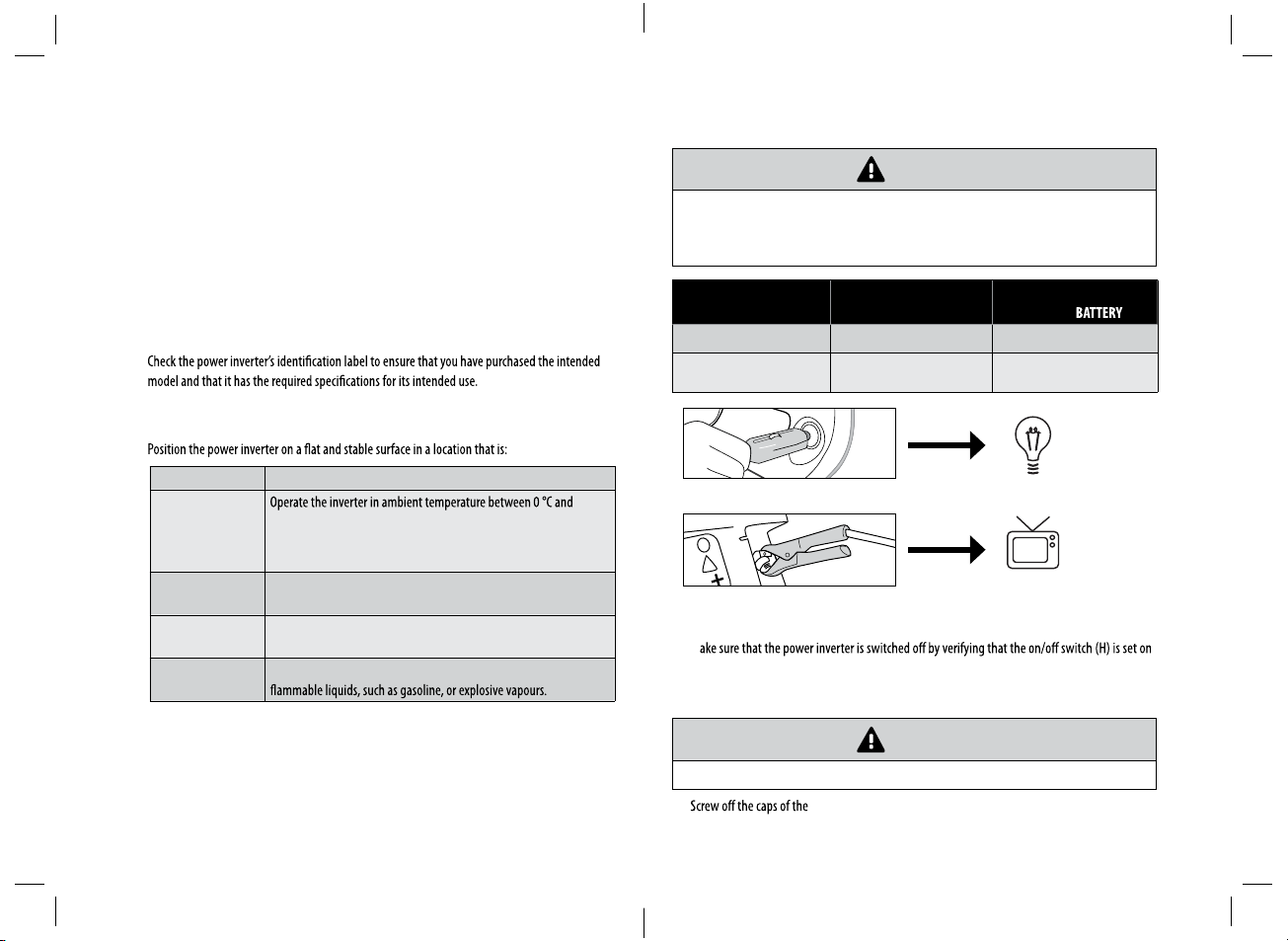
• REVERSE POLARITY. Power connections from a 12V battery to the power inverter must
be positive to positive and negative to negative. A reverse polarity connection (positive to
negative) will blow a fuse in the inverter and might permanently damage the unit. Damage
caused by a reverse polarity connection is not covered by your warranty.
• Disconnect the power cable whenever the engine is switched o for extended periods of
time. In some vehicles, the power does not turn o after the engine has been switched o. If
the plug is left connected, the vehicle battery might become discharged or damaged.
• Using the device for extended periods of time can completely discharge the vehicle battery.
• When using a power inverter continuously inside a vehicle that is not running, the engine
should be started at least once an hour for 10–15 minutes to keep the battery from
discharging. Do not start a vehicle in a closed garage, as the carbon monoxide in the exhaust
is fatal.
• Power inverters work best with a battery that is in good condition and fully charged. A weak
battery will be drained easily if demands are too high.This could leave you stranded so be
sure to check the battery’s condition before using a power inverter in a stationary vehicle.
SAFETY INFORMATION
SAFETY INFORMATION
011-1870-6-Mobile-Power-Outlet_300W-EN-07.indd 5-6 12/13/12 7:22 PM

87
ON/OFF SWITCH H
AC OUTLET E
VENTILATION OPENINGS A
GREEN INDICATOR F
RED INDICATOR G
DC CABLE WITH CIGARETTE
LIGHTER PLUG J
USB PORT D NEGATIVE DC CABLING TERMINAL B
VENTILATION OPENINGS A
POSITIVE + DC CABLING TERMINAL C
VENTILATION OPENINGS A
DC CABLE WITH CLAMPS FOR DIRECT
CONNECTION TO 12 V VEHICLE BATTERY I
KEY PARTS DIAGRAM
KEY PARTS DIAGRAM
011-1870-6-Mobile-Power-Outlet_300W-EN-07.indd 7-8 12/13/12 7:22 PM

109 The MotoMaster® Eliminator® Mobile Power Outlet is an electronic device that converts the low
voltage (direct current) from a battery, as can be found in cars, motor homes, boats or other
similar power sources, to the conventional 115 V (alternating current) like you have in your home.
Do not connect this inverter to batteries below 6V and above 16 V as it might get damaged.
This conversion process thereby allows you to run standard household devices such as a cell phone,
digital camera, portable work light, portable DVD player, battery charger, stereo system, laptop
similar devices in automobiles, boats, tractors, trucks and virtually anywhere else.
most devices adequately.
Options for connecting devices to the power inverter
According to the wattage of the devices and their features, you can choose to connect the device to the:
AC OUTLET
USB PORT
Determining the maximum load of connected devices
WARNING!
DO NOT overload your power inverter! Overloading the inverter, even for a short time, could
result in serious damage to the inverter and/or to the connected device.
A few simple steps are necessary to avoid overloading the inverter:
• Identify all devices that you would like to power.
• Add up the total wattage of devices that will be powered. The wattage can be found on the
individual device’s rating plate, as well as in the instruction manual.
IMPORTANT!
In some cases, the wattage might not be listed on the devices you want to connect to the
inverter. In that case, calculate the wattage using the following equation:
VOLTS x AMPERE = WATTS
Formula: 120 Volts x XAmpere = XXXX Watts
Example: 120 Volts x 2Ampere = 240 Watts
CAUTION!
(starting) wattage.
The RATED (RUNNING) WATTAGE is the average amount of power that a device consumes
continuously.
The SURGE (STARTING) WATTAGE is the amount of power that a device consumes at start-up for
a limited period of time (2-3 seconds). Some devices (e.g. induction motors of drills and fans) may
have a start-up surge of 3 to 7 times the rated wattage.
IMPORTANT!
The power inverter can supply momentary surge power that is higher (480W) than its maximum
power rating (240W). Some products with a rated wattage lower than the maximum power rating
for your inverter may still exceed the inverter's surge capability and trigger an overload shutdown.
OPERATION
INTENDED USE
011-1870-6-Mobile-Power-Outlet_300W-EN-07.indd 9-10 12/13/12 7:22 PM

1211 Products rated with the following power and surge ratings or less can be connected to the power
inverter.
POWER RATING MAXIMUM WATTAGE
5 min max. power rating 300 W
Continuous power rating (RATED WATTAGE) 240 W
Surge rating max. (SURGE WATTAGE) 480 W
Wattage of commonly used devices
IMPORTANT!
the operating instructions of devices to be used.
PRODUCTS WATTS
Portable music /MP3 player 1–5 W
Cell phone 10 W
Digital camera 15 W
Handheld gaming device 20 W
Portable work light 25 W
Portable DVD player 30 W
Battery charger 35 W
Stereo system 50 W
Laptop computer 75 W
13”television 100 W
Soldering gun 132 W
Finishing sander 176 W
27”television 200 W
3/8”drill 220 W
12”3-speed fan 231 W
NOTE: Power requirements for product examples are estimates only. To calculate the wattage of a
product, use the following equation: amperage x 115.
OPERATION
OPERATION
IMPORTANT!
Add up the total wattage of devices to be powered.
TAKE INTO CONSIDERATION THE SURGE WATTAGE REQUIRED BY ELECTRICAL MOTORS
AS WELL AS THE RATED WATTAGE.
Example:
These devices can be operated simultaneously.
DEVICE SURGE (STARTING) WATTAGE
MAX. 480 W
RATED (RUNNING) WATTAGE
MAX. 240 W
Light bulb 40 40
Table fan 400 200
Total wattage used 440 240
These devices usually CAN be connected to the MotoMaster® Eliminator® Mobile Power Outlet:
These devices usually CANNOT be connected to the MotoMaster® Eliminator® Mobile Power Outlet,
as they might have a start-up surge or continuous rating that is too high.
> 300 W
IMPORTANT!
The device is not suitable for professional or industrial use.
011-1870-6-Mobile-Power-Outlet_300W-EN-07.indd 11-12 12/13/12 7:22 PM

1413
OPERATION
Before you start
• Unpack the power inverter. Inspect the unit for damage. If the unit has been damaged, contact
the retailer immediately.
The carton should contain:
• Power inverter
• DC cable with cigarette lighter plug (J)
• DC cable for direct connection to 12 V battery (I)
• Owner’s manual
•
• Positioning of the power inverter:
DRY Do not expose to water, rain, moisture, snow or spray.
COOL
40 °C (32 °F and 104 °F). Keep it away from heating vents and direct
sunlight. We recommend using the inverter in environments not
exceeding 25 °C (77 °F).
WELL-VENTILATED For proper cooling, allow at least 2" (5 cm) of clearance around the
inverter.
CLEAN Choose a location that is free of any debris that could get into the
inverter.
SAFE Do not install the inverter in a compartment with batteries or
OPERATION
Connecting the MotoMaster® Eliminator® Mobile Power Outlet
CAUTION!
Prior to connecting to the power source:
Make sure that the total wattage of the devices you are planning to connect to the power
inverter does not exceed the maximum load of the respective power outlet.
LOAD CONNECTED (W)CONNECTION WITH
CIGARETTE LIGHTER PLUG
CONNECTION WITH
VEHICLE
Continuous load under 100 W Yes Yes
Continuous load between
100 and 240 W No Yes
< 100 W
< 240 W
Connecting the connector cables to the power inverter
• M
the "0" position.
• Choose the DC cable (I / J) suitable for connecting the AC products that you want to operate.
CAUTION!
Only use the cables provided with your power inverter.
• DC cabling terminals (B / C).
011-1870-6-Mobile-Power-Outlet_300W-EN-07.indd 13-14 12/13/12 7:22 PM

1615
OPERATION
• Connect the cable with the DC cabling terminals (B / C).
CAUTION!
Make sure to connect the RED CABLE TO POSITIVE PORT (+) and the BLACK CABLE TO
NEGATIVE PORT (-).
• Place the red cable connector on the positive DC cabling terminal (+ / red). Make sure that the
respective holes are matching. Screw the red cap back on the cabling terminal until the cable
POSITIVERED
CABLE CONNECTOR
• Place the black cable connector on the negative DC cabling terminal (- / black). Make sure that the
respective holes are matching. Screw the black cap back on the cabling terminal until the cable
NEGATIVE BLACK CABLE
CONNECTOR
OPERATION
Connecting the inverter to a lighter socket (loads under 100 W)
• Follow the instructions in the previous section. Choose the D
( Connecting the connector cables to the power inverter).
• Plug the cigarette lighter plug into the lighter socket of your vehicle. Make sure the plug is fully
inserted.
• The power inverter is now ready for use.
CAUTION!
Always disconnect the power cable from the cigarette lighter socket when you are not using the
device.
IMPORTANT!
The normal voltage drop that occurs when the vehicle's engine is started may trigger the
inverter's low-voltage shutdown feature. We recommend having the inverter disconnected from
the cigarette lighter plug while starting the engine.
Connecting the inverter to a 12 V vehicle battery (loads up to 240 W)
011-1870-6-Mobile-Power-Outlet_300W-EN-07.indd 15-16 12/13/12 7:22 PM

1817 Safety guidelines for handling batteries
DANGER!
A spark may be visible when making the connection to a battery because a
current will ow to charge the capacitors in the inverter. Do not make this
connection in the presence of ammable fumes. Explosion or re may result.
Thoroughly ventilate the battery compartment before making this connection.
DANGER!
Take special care when working with a car battery. Batteries contain corrosive
materials and present an ELECTRICAL SHOCK HAZARD.
DANGER!
Do not use the car battery in the proximity of open ames. Do not smoke when
using a car battery.
WARNING!
Remove any jewellery (watch, ring, etc.). Be careful not to short-circuit the battery with any
metallic object (wrench, etc.).
WARNING!
To prevent irritation and burns, wear protective eyewear and clothing when you
install the inverter or work with a vehicle battery. Should battery acid come
into contact with skin or eyes, ush it with water and consult your physician.
CAUTION!
Power connections from a 12V battery to the power inverter must be POSITIVERED TO
POSITIVE AND NEGATIVE BLACK TO NEGATIVE. A reverse polarity connection (positive
to negative) will blow a fuse in the inverter and may permanently damage the unit. Damage
caused by a reverse polarity connection is not covered by your warranty.
CAUTION!
Loose connectors result in an excessive voltage drop and may result in overheated wires and
melted insulation.
CAUTION!
Do not start the vehicle engine during operation.
• Follow the instructions in the section ( Connecting the connector cables to the power inverter)
to connect the DC cable to the inverter.
• If the battery can be switched o, switch it o.
• Fasten the positive / + (red) clamp to the positive / + battery post, and then fasten the negative
/ - (black) clamp to the negative / - battery post. Make sure to have a secure connection.
• The power inverter is now ready for use.
OPERATION
OPERATION
011-1870-6-Mobile-Power-Outlet_300W-EN-07.indd 17-18 12/13/12 7:22 PM

2019
OPERATION
OPERATION
CAUTION!
If you are going to disconnect the battery, switch the inverter o rst ( Switchingon/o).
CAUTION!
Always disconnect the power cables from the vehicle battery when you are not using the device.
Switching on/o
• Be sure to have your power inverter properly placed and connected according to the wattage that
is to be connected before attempting to switch it on.
• Switch the battery on in case it is switched o.
• Set the on/o switch (H) to the "I" position to switch on the inverter.
The green inidcator (F) lights up, indicating that the inverter is operating normally and that the
AC outlet and the USB port are powered.
• Plug in the devices that you want to operate to either the AC outlet or the USB port.
CAUTION!
After plugging in the devices, turn them on ONE AT A TIME.This will ensure that the inverter
does not have to deliver the surge currents required for all the loads at once.
• Set the on/o switch (H) to the "0" position to switch o the inverter.
CAUTION!
Switch the inverter o and disconnect it from the power source when it is not in use.
IMPORTANT!
When the inverter is switched o, it draws no current from the battery.When the inverter is
switched on without any load connected to it, the inverter draws approx. 0.3 A from the battery.
This low current draw will eventually discharge the battery.
Using the USB port
Plug the USB-powered device into the inverter’s USB port (D) and operate normally.
IMPORTANT!
This unit’s USB charging port does not support data communication. It only provides (5V/2.1 A)
DC power to an external USB-powered device. Not all mobile phones are provided with a
charging cable. Data cables are not supported by this device. Please check with your mobile
phone dealer for the correct charging cable.
011-1870-6-Mobile-Power-Outlet_300W-EN-07.indd 19-20 12/13/12 7:22 PM

2221
OPERATION
Automatic safety features
The MotoMaster® Eliminator® Mobile Power Outlet includes the following automatic safety features
to ensure safe and trouble-free operation:
• Vehicle battery low-voltage automatic alarm and shutdown: activated when the battery voltage
drops to 10–11V, to protect the battery from being damaged.
• Vehicle battery high-voltage automatic shutdown: activated when the battery voltage rises to a
dangerously high level due to a defective battery.
• Overload protection with automatic shutdown: activated when a device rated more than 100W is
plugged into the inverter.
• Overheat protection with automatic shutdown: activated in case the inverter overheats due to
improper ventilation or a high ambient temperature.
• Output short-circuit protection: activated in case of a short-circuit in the connected device.
•
it exceeds its ambient operating temperature.
•
should be replaced manually, if necessary.
The RED INDICATOR (G) indicates a shutdown of the inverter due to low-voltage, high-voltage,
overloading or overheating.
An AUDIBLE ALARM warns you if a low-voltage or a high-voltage shutdown is about to occur
(
WARNING!
the power source.
• The exterior of the device should be cleaned periodically with a damp cloth or sponge and a mild
soap solution.
• Be sure vents and fans are free of dust or debris.
• Never immerse the device in water or any other liquid.
•For cleaning never use corrosive detergents, wire brushes, abrasive scourers, or metal or sharp objects.
• Store the device in a cool, dry location that is protected from moisture and out of the reach of
children.
Maintaining battery condition
• Vehicle batteries are designed to provide brief periods of very high current needed for engine
starting. They are not intended for constant deep discharge.
• Regularly operating the power inverter from a vehicle's battery until the low-voltage alarm
sounds will shorten the battery's life.
• The battery operating time depends on:
• the charge level of the battery,
• the battery capacity,
• the amount of power drawn by the devices that are connected to the inverter.
• With an average load of about 240W connected to the inverter, consider that the engine should
be started at least once an hour for 10–15 minutes to keep the battery from discharging.
•
the battery or the cigarette lighter socket.
• While the engine is running, the power inverter can be connected to the cigarette lighter socket
again.
• Consider connecting the power inverter to a separate deep-discharge type of suitable battery if
you will be frequently running electrical devices for extended periods of time.
MAINTENANCE
011-1870-6-Mobile-Power-Outlet_300W-EN-07.indd 21-22 12/13/12 7:22 PM

2423
MAINTENANCE
TROUBLESHOOTING
Fuse replacement
WARNING!
For continued protection against risk of re or electric shock, replace only with a fuse of the same
type and ratings (12 V, 8 A).
Follow the instructions to replace the fuse inside the cigarette lighter plug of your connector cable (J):
Unscrew the upper cover of the cigarette lighter plug.
Remove the faulty fuse.
Insert a new fuse and screw the cover of the plug back on.
NEW FUSE
FAULTY FUSE
The inverter is equipped with protective shutdown features and an acoustic signal.
The details are listed in the following table:
ALARM POSSIBLE CAUSE SOLUTION ERROR
SIGNAL
Low battery
alarm and
low-voltage
shutdown
As the battery discharges, its
voltage decreases. Voltage drops
to: 10.5–11.0 V = alarm.
Shut down sensitive loads such as
computers and then recharge the
battery.
Audible
alarm
Voltage drops to:
10.0–10.5 V = shutdown.
This protects the battery from
being over-discharged.
Recharge the battery.
Red
indicator
light (G)
turns on
High-
voltage
shutdown
A defective battery charging
system can cause the battery
voltage to rise to high levels
(15.0–16.3 V).
Although the inverter has a
protection against high voltage,
it might still be damaged if the
input voltage were to exceed 16 V.
Disconnect the connected devices.
Verify that the charging system is
properly regulated and the battery is
12V nominal.
Red
indicator
light (G)
turns on
Overload
shutdown
If you connect a device that is
rated too high or a load that draws
excessive surge power, the power
inverter shuts down.
Use a product with a power rating
within the inverter’s continuous
power rating (Operation).
Red
indicator
light (G)
turns on
Overheat
shutdown
The power inverter shuts down
automatically if it exceeds its safe
operating temperature.
• Switch the inverter o and
disconnect it from the cigarette
lighter socket.
• Disconnect all connected devices
and allow the inverter to cool for
at least 15 minutes.
• Use a brush to clear any blocked
ventilation holes.
• Move the inverter to a cooler
place. Reduce the load if
continuous operation is required.
Red
indicator
light (G)
turns on
011-1870-6-Mobile-Power-Outlet_300W-EN-07.indd 23-24 12/13/12 7:22 PM

2625 PROBLEM POSSIBLE CAUSE SOLUTION
The connected device
does not switch on.
The battery is defective. Check the battery and replace it if
required.
The inverter is damaged and
needs to be repaired.
Have the inverter repaired by an
authorized service centre.
Incorrect connections to the
inverter.
Check all connections. Make sure the
connection is correct and tight.
The inverter will run
some small loads, but
not larger ones.
The cables are either too long
or not heavy enough.
Only use the cables provided with
your power inverter.
Measured inverter
output is too low. The battery voltage is too low. Recharge the battery.
Battery run time is less
than expected.
The AC product power
consumption is higher than
rated.
Use a larger battery to make up for
the increase in power requirement.
The battery is old or defective. Replace the battery.
The battery is not being
charged properly.
Some chargers are not able to fully
recharge a battery. Make sure that
you use a powerful charger.
Power dissipation in DC cables. Only use the cables provided with
your power inverter.
No power to inverter. Blown fuse. Replace fuse.
Buzz in the audio
system.
Inadequate internal power
supply ltering of stereo
system.
Use an audio system with a high-
quality lter.
Television interference. TV signals are weak.
• Adjust the orientation of the
power inverter, television,
antenna and cables.
• MaximizeTV signal strength by
using a better antenna and use
shielded antenna cable where
possible.
• Try a dierentTV model.
This MotoMaster® Eliminator® product carries a one (1) year warranty against defects in
workmanship and materials. At its discretion, MotoMaster Canada agrees to have any defective
part(s) repaired or replaced free of charge, within the stated warranty period, when returned by the
original purchaser with proof of purchase.This product is not guaranteed against wear or breakage
due to misuse and/or abuse.
TROUBLESHOOTING
WARRANTY
011-1870-6-Mobile-Power-Outlet_300W-EN-07.indd 25-26 12/13/12 7:22 PM
Other manuals for Eliminator
1
Table of contents
Popular Portable Generator manuals by other brands

RPS sonic
RPS sonic HZ-2000 Operate Manual

Powermate
Powermate PM0601350 user manual

North Star
North Star 10500 SBG Installation and operation manual

Champion Global Power Equipment
Champion Global Power Equipment CPG4000DHY-EU Operator's manual

Saluki
Saluki S1465 Series user manual

AlzaPower
AlzaPower APW-PS600 user manual

SR PORTABLES
SR PORTABLES Minotaur instruction manual

Fischer Panda
Fischer Panda PMS 9000ND Operation manual

Predator
Predator 59134 Owner's manual & safety instructions

Westerbeke
Westerbeke 7.5 MCGA Operator's manual

Baumalight
Baumalight KR Series Operator's manual

Ambionair
Ambionair TDG2500E owner's manual