Motomaster ELIMINATOR 140-0050-6 User manual
IMPORTANT:
Please read this manual carefully before using this winch and save it
for reference. Keep this instruction manual for future use. Should this
product be passed on to a third party, this instruction manual must be
included.
model no. 140-0050-6
INSTRUCTION
MANUAL
ATV WINCH KIT
4700 lb (2132 kg)
model no. 140-0050-6 | contact us 1-888-942-6686
2
SERVICE INFORMATION
For customer assistance please call

TABLE OF CONTENTS
3
TABLE OF CONTENTS
Service Information 2
Introduction 4
Safety Definitions 4
Important Safety Instructions 5
Safety Symbols 7
Operation Symbols 7
Key Parts Diagram 8
Key Parts List 10
Assembly 11
Mounting the Winch 11
Solenoid/Contactor Location 13
Installing the Mini-rocker Switch 14
Wiring the Winch 15
Wiring Diagram 17
Switch Wiring Diagram 18
Operation 19
General Tips for Safe Operation 19
Self Recovery 20
Synthetic Rope Abrasion Sleeve 21
Winching Techniques A-Z 22
Maintenance 24
Lubrication 25
Synthetic Rope Replacement 25
Specifications 28
Performance Specifications 28
Troubleshooting 29
Warranty 30
Parts Diagram 32
Parts List 33
Motor Parts Diagram 36
Motor Parts List 37

4
INTRODUCTION
model no. 140-0050-6 | contact us 1-888-942-6686
INTRODUCTION
This MotoMaster®Eliminator ATV Winch Kit
includes everything you need to start winching,
including cables, contactor, mounting channel,
aluminum hawse, a wiring kit and mini-rocker
switch. This winch kit is the perfect combination
of power and performance to use with your ATV,
trailer, boat or snowmobile.
This manual will explain how to use the winch
safely and effectively. Please read and follow
these instructions and precautions carefully.
SAFETY DEFINITIONS
The purpose of safety symbols is to attract
your attention to possible dangers. The safety
symbols, and their explanations, deserve your
careful attention and understanding. The safety
warnings do not by themselves eliminate any
danger. The instructions or warnings they give
are not substitutes for proper accident prevention
measures.
DANGER
DANGER indicates a hazardous situation which, if not
avoided, will result in death or serious injury.
WARNING
WARNING indicates a hazardous situation which, if
not avoided, could result in death or serious injury.
CAUTION
CAUTION indicates a hazardous situation which, if not
avoided, could result in minor or moderate injury.
NOTICE
NOTICE indicates information considered important,
but not hazard-related (e.g., messages relating to
property damage).

5
IMPORTANT SAFETY INSTRUCTIONS
WARNING!
• Never use winch to lift or move persons or animals.
• Never use winch as a hoist or to suspend a load.
• Never step over the cable/rope when operating under load.
• Never operate winch with less than 5 wraps of rope around the drum. Rope could come loose from the
drum as the rope attachment to the drum is not designed to hold a load.
WARNING!
• Never exceed the rated capacity. Be aware that the cable/rope may break before the motor stalls.
• For heavy loads at or near rated capacity, always use a snatch block to reduce the load on the cable/rope.
WARNING!
• Do not use the winch to secure or hold a vehicle for an extended period of time.
• Always apply stop blocks to the wheels of the vehicle when on an incline.
• Do not use the winch to secure a vehicle for transporting purposes.
• Never move the vehicle to pull a load (towing) when operating the winch cable/rope.
• Never release the free-spool clutch when there is a load on the winch.
WARNING!
Disconnect the mini-rocker switch and battery leads when not in use.
WARNING!
Avoid “shock loads” by using the control switch intermittently to take up the slack in the cable/rope.
“Shock loads” can exceed the rated capacity of the cable/rope and drum.
WARNING!
When re-spooling the cable/rope, ensure that it spools in the under-wind position with the cable/rope
entering the drum from the bottom, not the top.
To re-spool correctly, and while wearing gloves, keep a slight load on the cable/rope while pushing the
mini-rocker switch button to draw in the cable/rope. Walk toward the winch not allowing the cable/rope
to slide through your hands. Do not let your hands get within 12" (30 cm) of the winch while re-spooling.
Turn off the winch and repeat the procedure until a few feet of cable/rope are left. Disconnect the mini-
rocker switch and finish spooling by rotating the drum by hand with the clutch disengaged. Keep hands
clear of the fairlead and drum while the winch is under power.
IMPORTANT SAFETY INSTRUCTIONS
model no. 140-0050-6 | contact us 1-888-942-6686
6
IMPORTANT SAFETY INSTRUCTIONS
WARNING!
• Always use extreme caution when handling hook and cable/rope during spooling operations.
• Always use supplied hand strap whenever spooling rope in or out, during installation and during operation.
WARNING!
Always wear heavy leather gloves when handling cable/rope.
CAUTION!
Do not wrap the cable/rope around any object and hook it back onto itself.
CAUTION!
Duration of winching pulls should be kept as short as possible.
If the motor becomes excessively hot to the touch, stop winching immediately and let it cool down for 5
minutes. Do not pull for more than one minute at or near the rated load.
CAUTION!
If the motor stalls, do not maintain power to the winch.
Electric winches are designed and made for intermittent use and should not be used in constant duty
applications.
SAFETY SYMBOLS
7
SAFETY SYMBOLS
Some of the following symbols may be used on
this product. Please study them and learn their
meaning. Proper interpretation of these symbols
will allow you to more safely operate the product.
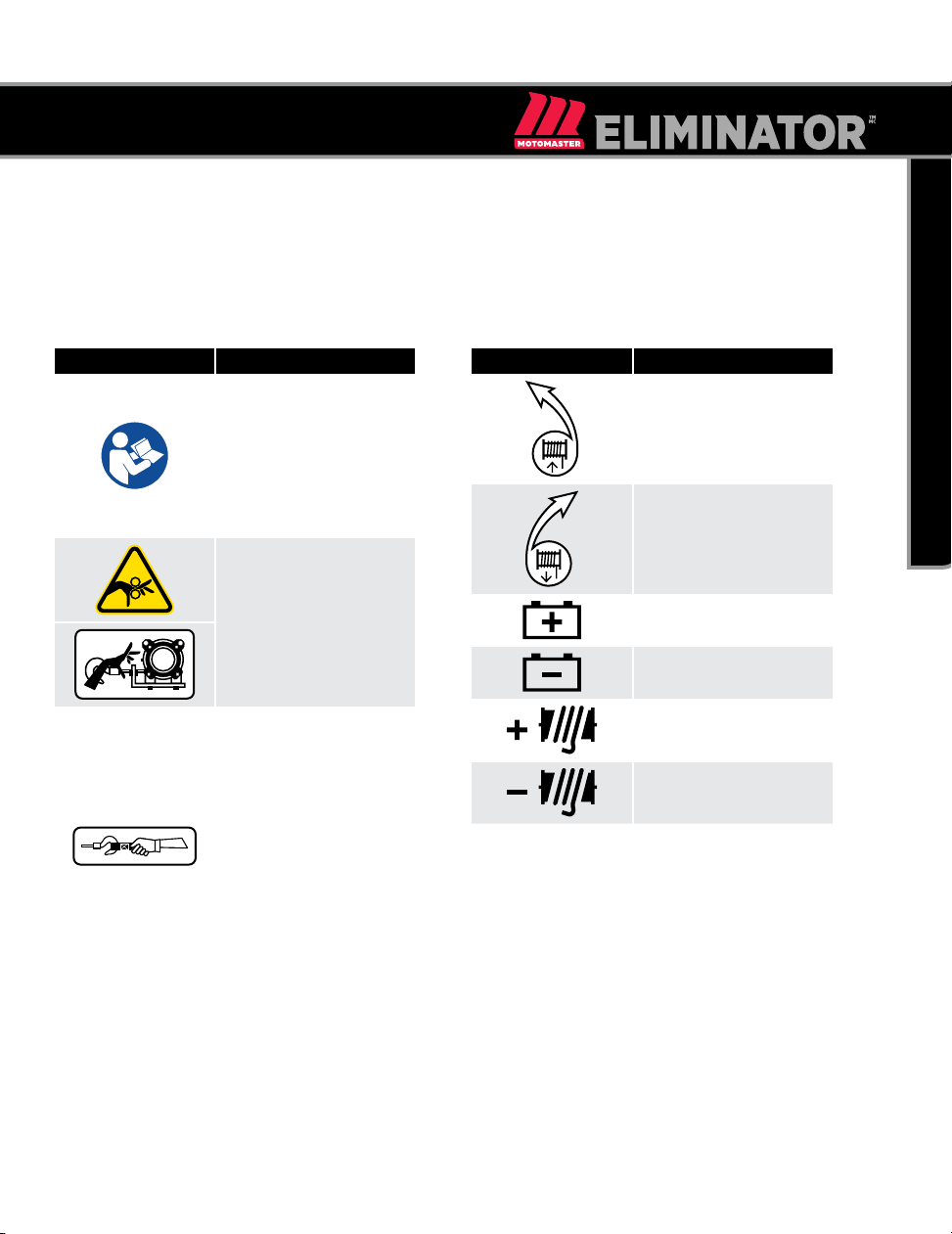
SYMBOL MEANING
Read and understand
this instruction manual
thoroughly before using
the product. It contains
important information
for your safety as well as
operating and maintenance
advice.
Always keep hands clear of
cable/rope, hook loop, hook
and hawse fairlead opening
during installation, operation
and when spooling in or out.
• Always use extreme
caution when handling
hook and cable/
rope during spooling
operations.
• Always use supplied hand
strap whenever spooling
rope in or out, during
installation and during
operation.
• Always wear heavy leather
gloves when handling
cable/rope.
OPERATION SYMBOLS
Some of the following symbols may be used on
this product. Please study them and learn their
meaning. Proper interpretation of these symbols
will allow you to more safely operate the product.
SYMBOL MEANING
Turn the clutch to the “IN”
position to retract the rope.
Turn the clutch to the “OUT”
position to release the rope.
Positive battery terminal
Negative battery terminal
Positive winch terminal
Negative winch terminal
model no. 140-0050-6 | contact us 1-888-942-6686
8
KEY PARTS DIAGRAM
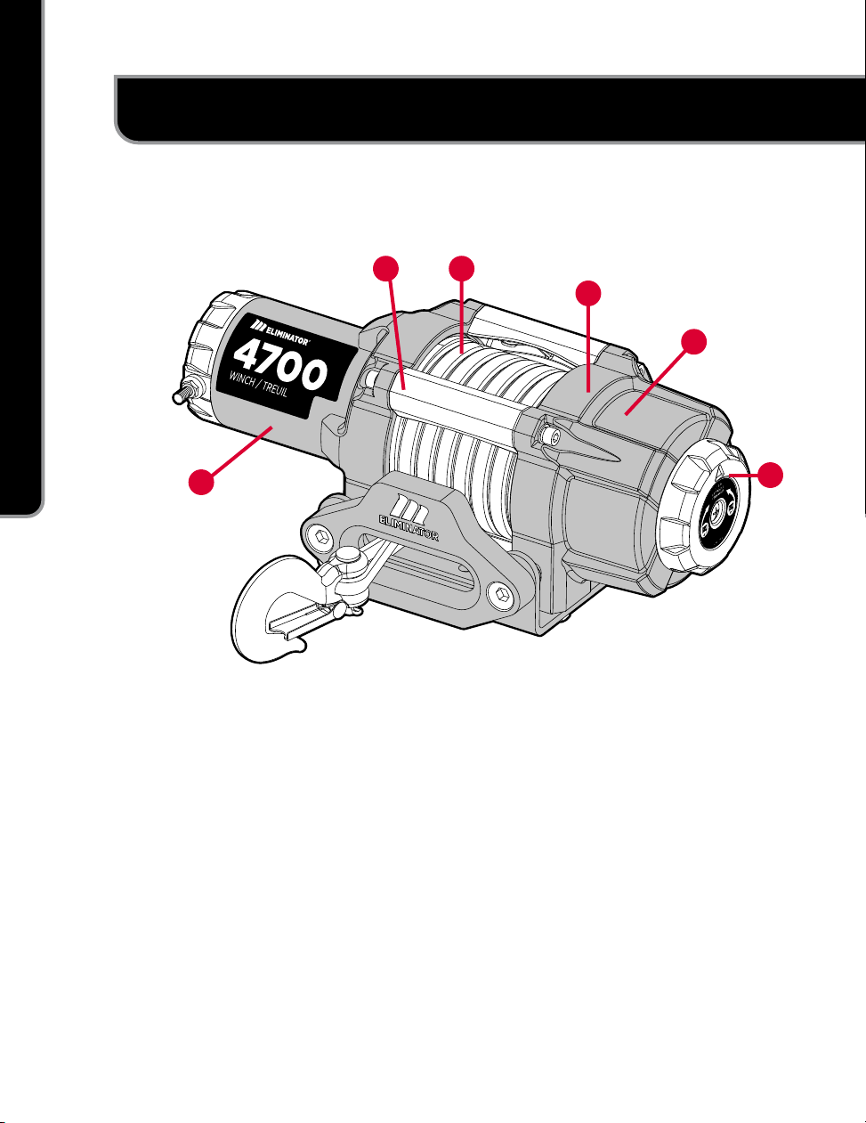
KEY PARTS DIAGRAM
1. Motor – 1.6 HP (1.2 kW) 12V DC motor
provides power to the planetary gear
mechanism.
2. Tie Bars – Durable all-metal construction tie
bars for increased structural rigidity.
3. Winch Drum – The winch drum is the
cylinder on which the synthetic rope
is stored. It can feed or wind the rope
depending on the remote winch switch.
4. Braking System – Braking action is
automatically applied to the winch drum
when the winch motor is stopped and there
is a load on the synthetic rope.
5. Planetary Gear System – The reduction
gears convert the winch motor power into
extreme pulling forces. This system allows
high torque while maintaining compact size
and light weight.
6. Clutch – The clutch allows the operator to
manually disengage (“Out”) the spooling
drum from the gear train, free spool.
Engaging the clutch (“In”) locks the winch
into the gear system.
2
16
3
4
5

9
KEY PARTS DIAGRAM
7. Hand Strap – Used to assist synthetic rope
feed.
8. Aluminum Hawse – When using the winch
at an angle the hawse acts to guide the
synthetic rope onto the drum and minimizes
damage to the synthetic rope from abrasion
on the winch mount or bumper.
9. Mini-rocker Switch – Rocker switch with
handlebar mount for powering the synthetic
rope in or out of your winch drum.
10. Solenoid/Contactor – Power from the
vehicle battery flows through the weather
sealed contactor before being directed to the
winch motor.
11. Mounting Channel – Winch mount to attach
the winch to your vehicle.
12. Winch Connection Cables – Used to
connect the contactor to the winch motor and
the contactor to the vehicle battery.
8
9
10
11
12
13
15
14
16
7
13. Synthetic Rope – 38' x 15/64"
(11.6 m x 6 mm) Synthetic rope designed
specifically for load capacity of 4,700 lb
(2,132 kg). The synthetic rope feeds onto the
drum in the “under wind” position through
the aluminum hawse and is looped at the
end to accept the clevis hook pin.
14. Clevis Hook – Provides a means for
connecting the looped ends of cables to an
anchor.
15. Wire Tap – Allows the ability to splice the
end of the red wire on the mini-rocker switch
to an ignition or keyed controlled power
source.
16. Cable Ties – Attaches the mini-rocker
switch cable to the chassis of your vehicle.

model no. 140-0050-6 | contact us 1-888-942-6686
10
KEY PARTS LIST
KEY PARTS LIST
PART PART
QTY. HARDWARE HARDWARE
QTY. TOOL(S) NEEDED
TORQUE
lbf-ft
(Nm)
Winch Body 1
Hexagon Head Bolt M8 x 25 4 1x 13 mm wrench 6.1–7
(8.2–9.5)
Flat Washer Ø8 4
Flat Washer Ø8 4
Mounting
Channel 1
Aluminum Hawse 1
Hexagon Socket Set Screw
M10 x 25 2 1x 8 mm wrench 11.8–12.6
(16–17.1)
Lock Nut M10 2 1x 16 mm wrench
Mini-rocker
Switch 1
Hexagon Socket Head
Screw M5 x 18 1 1x 4 mm wrench 2.2–3
(3–4)
Hexagon Socket Head
Screw M5 x 25 2 1x 4 mm wrench
Flat Washer Ø5 3
Nut M5 3 1x 8 mm wrench
Wire Tap 1
Contactor 1
Hexagon Head Bolt M6 x 25 4 1x 10 mm wrench 4.1–4.9
(5.6–6.6)
Flat Washer Ø6 4
Lock washer Ø6 4
Lock Nut M6 4 1x 10 mm wrench
Battery Wire —
Red 1
Battery Wire —
Black 1
Winch Wire —
Yellow 1
Winch Wire —
Blue 1
Clevis Hook 1 Needle nose pliers
Hand Strap 1
ASSEMBLY
11
ASSEMBLY
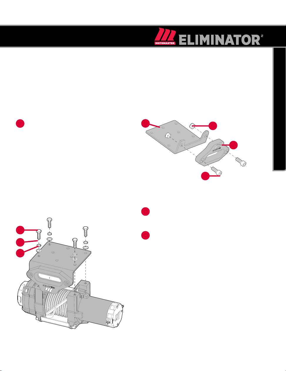
MOUNTING THE WINCH
The MotoMaster®Eliminator ATV Winch Kit is designed with a bolt pattern that is standard in this class of
winch. Many winch mounting kits are available that utilize this bolt pattern for the most popular trucks,
SUVs and ATVs.
Insert M10×25 (A) bolts through the
mounting channel (B) holes and attach the
aluminum hawse (C) to the mounting channel
with the M10 lock nuts (D) provided.
1
2
3
B
G
F
E
A
D
C
Turn the winch upside down. Place the
mounting channel on the winch, making sure
the winch is centred in the middle of it.
Thread the M8×25 (E) bolts through the Ø8
lock (F) and flat washers (G), and then thread
through the mounting channel. Tighten the
bolts. DO NOT overtighten.

model no. 140-0050-6 | contact us 1-888-942-6686
12
ASSEMBLY
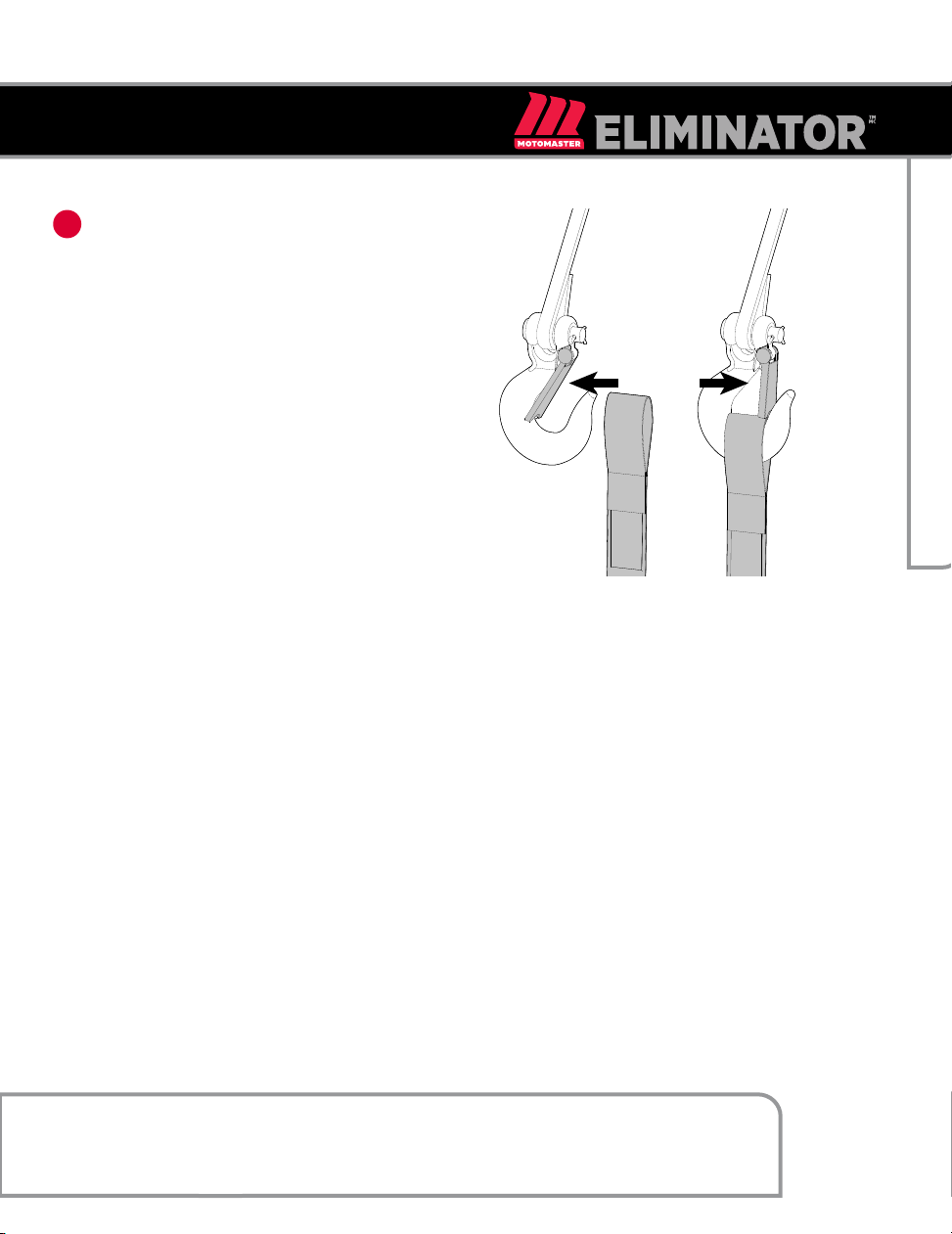
4Turn winch right side up. Disengage the
clutch by moving the clutch to the “Out”
position — the arrow will be to the back of
the winch as shown. Release the synthetic
rope and pull through the aluminum hawse.
CAUTION!
See Key Parts List section for torque ratings. Mounting bolts must be SAE grade 5 or better and torqued to
34 lbf-ft (46 Nm).
CAUTION!
If utilizing a mounting plate, ensure that the three major sections (motor, drum and gear housing) are
properly aligned. Proper alignment of the winch will allow for even distribution of the full rated load.
The type of vehicle to which the winch and mounting channel will be applied, will dictate the type of
mounting kit that should be used.
5Attach the clevis hook to the synthetic rope
by removing cotter pin and pin, then thread
through and reattach the pin and cotter pin.
CLUTCH
OUT
13
ASSEMBLY
6Add hand strap to the clevis hook.
SOLENOID/CONTACTOR LOCATION
Find a location for the solenoid/contactor. It is recommended that the solenoid/contactor be mounted close
to the battery in a clean, dry location. Make sure the location chosen allows for sufficient clearance from all
metal components. Drill mounting holes if required. Once a location is found, DO NOT install the unit until all
wiring is completed (see wiring section).
NOTICE:
Terminals coming in contact with metal will cause a direct short, possibly causing solenoid/contactor and/
or battery damage.
model no. 140-0050-6 | contact us 1-888-942-6686
14
ASSEMBLY
1
2
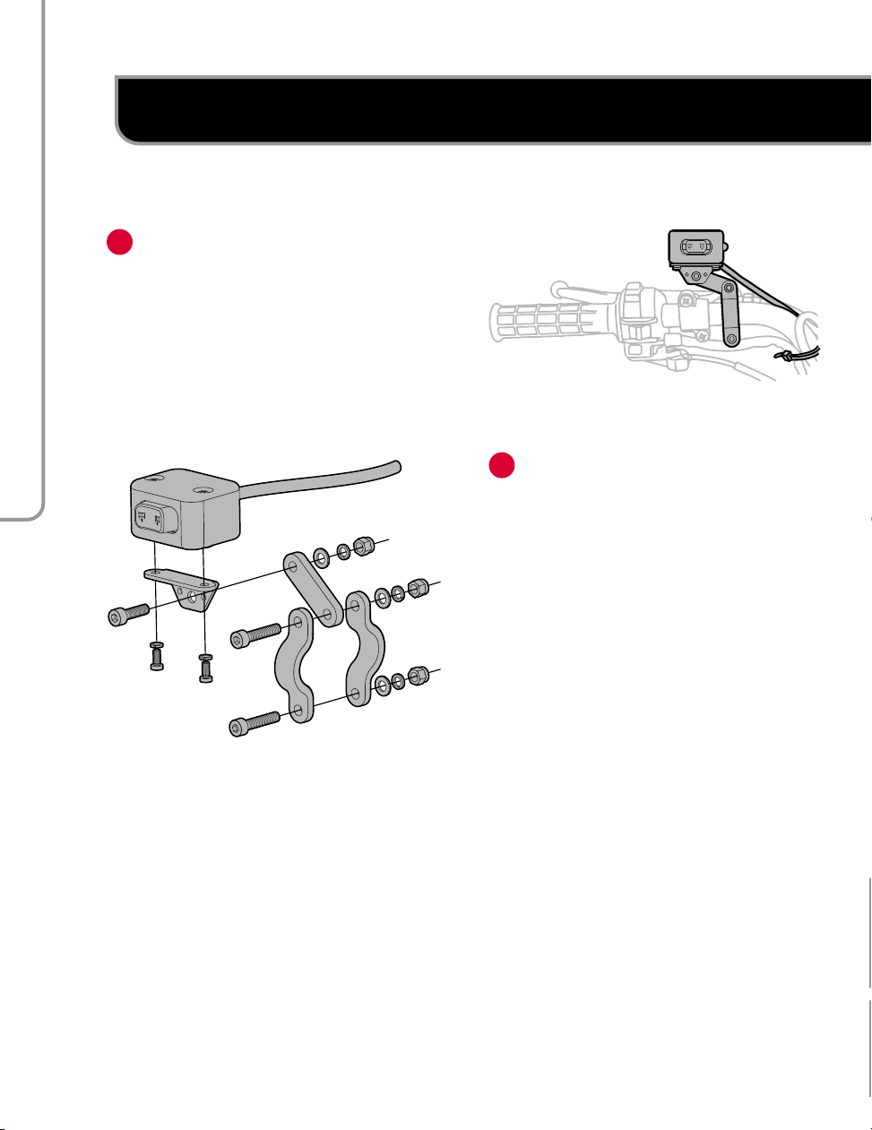
INSTALLING THE MINI-ROCKER SWITCH
Decide which handlebar the mini-rocker
switch will be mounted on. The mini-
rocker switch is usually installed on the left
handlebar.
Use a piece of electrical tape (not provided)
around the handlebar to help prevent rotation
of the mount.
Loosen the hardware and mount to the
handlebar.
Tighten the mini-rocker switch in place. DO
NOT overtighten or tighten/clamp over any
hoses or cables.
Once the mini-rocker switch is mounted,
the wires can be routed back to where the
solenoid/contactor is located.
Make sure the handlebars have full range
of motion and then secure the mini-rocker
switch’s cable with the supplied cable ties.
15
ASSEMBLY
WIRING THE WINCH
See the wiring diagram on the following page for
these following steps
Connect the yellow and blue cables to the
motor terminals on the winch (yellow to
the positive (+) terminal of the motor; blue
to the negative (-) terminal of the motor).
Tighten the terminal nuts on the motor. DO
NOT overtighten. Route the other ends to the
solenoid/contactor location.
Connect the yellow and blue cables to the
solenoid/contactor (yellow to yellow and blue
to blue). DO NOT tighten nuts.
Connect the red and black cables to the
solenoid/contactor (red to red and black to
black). DO NOT tighten nuts. Route the other
ends to the vehicle’s battery.
1
2
3
4
9
5
6
7
8
CAUTION!
NEVER route electrical cables across any sharp edges, through and/or near moving parts, or near parts
that may become hot.
Battery cables should NOT be drawn tight. Leave some slack for cable movement.
NOTICE:
You may need to use a test light to locate a suitable wire. The wire should only have power when the key
is in the ON position.
Connect the red lead to the positive (+)
terminal of the vehicle’s 12V battery.
Connect the mini-rocker switch to the
solenoid/contactor (black to black and green
to green).
Splice the end of the red wire on the mini-
rocker switch to an ignition (keyed) controlled
power source using the supplied wire tap.
Once all wiring is connected to the solenoid/
contactor, it can then be mounted using the
supplied M6 hardware.
Tighten the solenoid/contactor terminal nuts.
DO NOT overtighten.
Connect the black lead to the negative (-)
terminal of the vehicle’s 12V battery.
Place all terminal boots over terminals and
secure all cables with cable ties or electrical
tape (not included).
10

model no. 140-0050-6 | contact us 1-888-942-6686
16
ASSEMBLY
NOTICE:
Depending on the location of the solenoid/contactor, you may need to use the black and red cables in
place of the yellow and blue, and the yellow and blue in place of the red and black.
Check for proper drum rotation. Turn the clutch to the “Out” position (free spooling). Pull out some
cable from the drum, and then turn the clutch to the “In” position to engage the gears.
11
12
CLUTCH
OUT
OUT IN
IN
Press the “Out” button on the mini-rocker switch. If the drum is turning and releasing more cable/rope,
then your connections are accurate. If the drum is turning and collecting more cable/rope then reverse
the leads on the motor. Repeat and check rotation. Press the “In” button on the mini-rocker switch as a
final test.
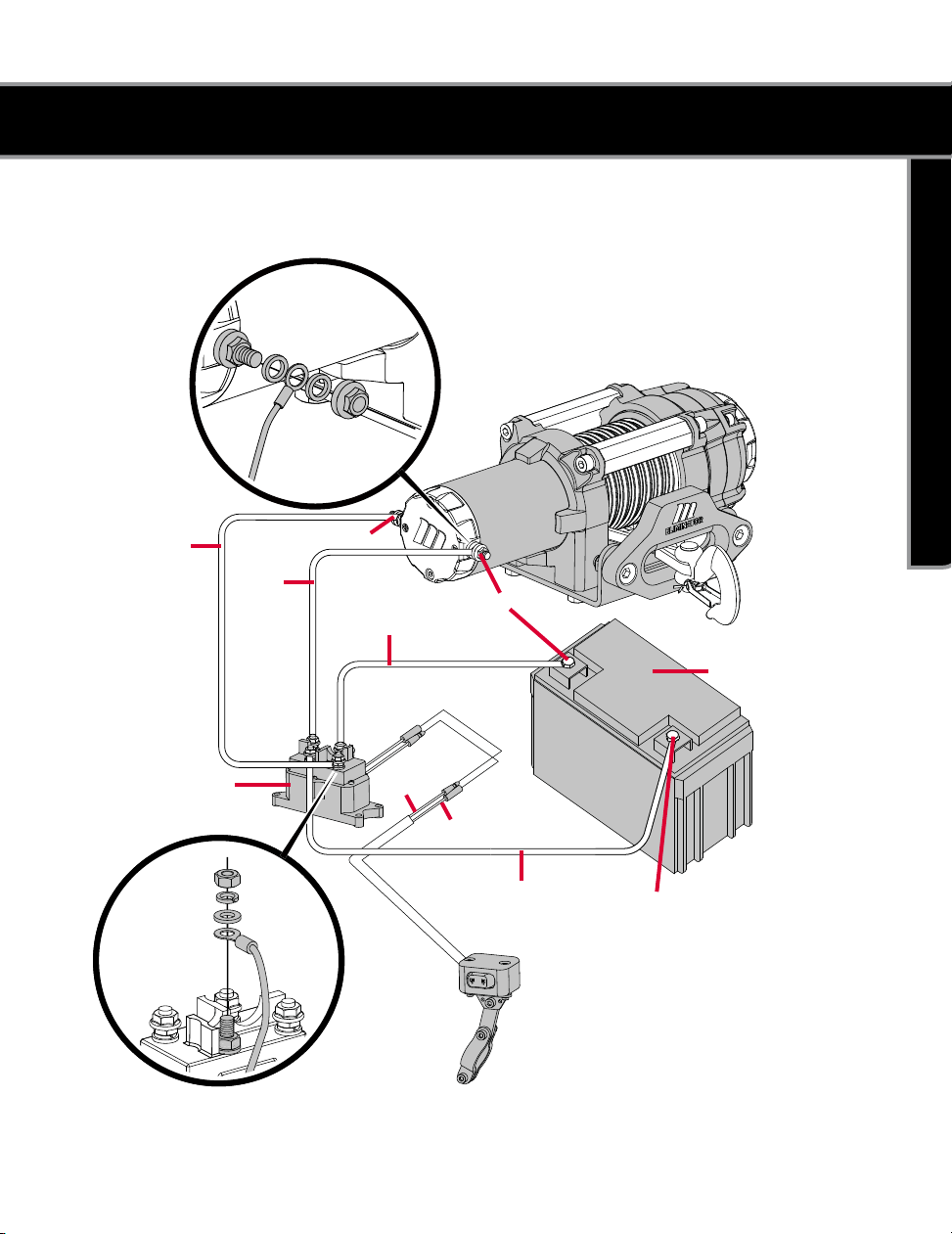
WIRING DIAGRAM
17
WIRING DIAGRAM
POSITIVE (+)
YELLOW
SOLENOID/CONTACTOR
BLACK
RED POSITIVE (+)
+
BATTERY
GREEN
BLACK
BLUE
NEGATIVE (–)
–

model no. 140-0050-6 | contact us 1-888-942-6686
18
SWITCH WIRING DIAGRAM
SWITCH WIRING DIAGRAM
GREEN
IGNITION WIRE
RED
BLACK

OPERATION
19
OPERATION
GENERAL TIPS FOR SAFE OPERATION
Your winch is rated at a 4,700 lb (2,132 kg)
capacity in first layer (max.) when spooling
the first rope layer on the drum. Overloads can
damage the winch, motor and/or synthetic
rope. For loads over 2,350 lb (1,066 kg), we
recommend the use of the pulley block/snatch
block to double the synthetic rope line. This will
aid in two ways:
• Reduce the number or rope layers on the
drum; as well as
• Reduce the load on the rope by as much as
50%.
When doubling the line back to the vehicle, attach
to the tow hook, frame or other load-bearing part.
The vehicle engine should be kept running during
operation of the winch to minimize battery drain
and maximize power and speed of the winch. If
the winch is used for a considerable time with the
engine off, the battery may be drained and too
weak to restart the motor.
Get to know your winch before you actually
need to use it. We recommend that you set up a
few test runs to familiarize yourself with rigging
techniques, the sounds your winch makes under
various loads, the way the cable/rope spools on
the drum, etc.
Inspect the synthetic rope and equipment before
each use. A frayed or damaged cable/rope must
be replaced immediately. Use only manufacturer’s
identical replacement rope with the exact
specifications.
Always inspect the winch installation and bolts
to ensure that all bolts are tight before each
operation.
Any winch that appears to be damaged in
any way, or operates abnormally MUST BE
REMOVED FROM SERVICE UNTIL REPAIRED. It
is recommended that the necessary repairs be
made by a manufacturer’s authorized repair
facility.
Pull only on areas of the vehicle as specified by
the vehicle manufacturer.
model no. 140-0050-6 | contact us 1-888-942-6686
20
OPERATION
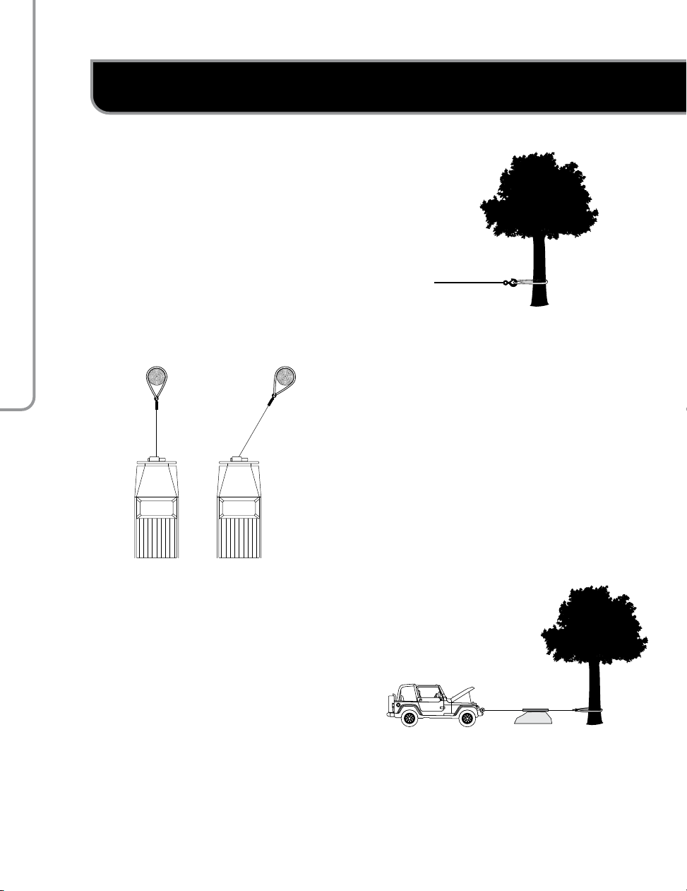
SELF RECOVERY
Locate a suitable anchor such as a strong tree
trunk or boulder. Always use a sling as an anchor
point.
Your winch is equipped with a aluminum hawse
to help guide the synthetic rope and to reduce
binding on short side pulls. Do not winch from an
acute angle as the synthetic rope will pile up on
one side of the drum causing damage to synthetic
rope and the winch.
Short pulls from an angle can be used to
straighten the vehicle. Long pulls should be done
with the synthetic rope at a 90° angle to the
winch/vehicle. When pulling a heavy load, place
a blanket or jacket over the synthetic rope 5 – 6’
(1.5 – 1.8 m) from the hook.
In the event of a broken cable/rope it will dampen
the snap back.
CORRECT INCORRECT
Table of contents
Popular Winch manuals by other brands

Come.up Winch
Come.up Winch 295750 12V manual

AWD
AWD AWD0907A instruction manual

Kolpin Outdoors
Kolpin Outdoors KAWASAKI MULE PRO-FX Assembly & owners manual

Keeper
Keeper Trakker KT2500 Assembly & operating instructions

Berger & Schroter
Berger & Schroter 31593 Instructions for use

Ronstan
Ronstan Andersen 28ST FS product manual

Westfalia
Westfalia 32 15 21 instruction manual

Tractel
Tractel caRol TR Operation and maintenance manual

Antal
Antal XT66EH installation manual

Startax
Startax 9201-10000-T User instructions

Comeup
Comeup Blazer M2 instruction manual

Ingersoll-Rand
Ingersoll-Rand force 5 Man-Rider FA2.5MRA Parts, operation and maintenance manual


