VIME INDUSTRIAL EPH EPHL 100 FN User manual

PLANETARY HYDRAULIC WINCH
WARNING
Read and understand this manual before installation and operation of winch.
V.I.M.E. srl
V
ia Gramsci,15 40050 Funo Bologna Italy Tel. +39 051 861362 Fax +39 051 861961
OPERATING SERVICE
AND MAINTENANCE MANUAL
EPHL 100 FN EPHL 125 FN
EPHL 150 FN EPHL 165 FN
ENGLISH
VIME Industrial has no responsability for physical injury to persons, animals or property damages. That can result from failure to read and
apply the instructions contained in the manual supplied with the winch and especially for: failure with global safety aspects - not correct
linking to the source of energy - deficiency in the annual and monthly maintenance - improper uses - any alteration, repair or modification
from unauthorized personnel.
12/2016 - UK - 13H - EN 14492-1
The Quality is Transparent
Because of continued product improvement, we
reserve the right to make changes without
notice.
SERVICE
PLANETARY
EN 14492-1

WARNING
Do not operate this winch until you have
fully read this manual.
Many accidents are due for non
observance safety procedures. A good
reason, most of it can be avoided by
knowing causes and taking in advance
the opportunity safety.
WARNING
Read and understand this manual before
installation and operation of winch.
Model EPHL 100 FN
EPHL 125 FN
Serial Number
Year
Rated line pull (single line) • EPHL 100 FN CE 10.000 Kg
• EPHL 125 FN CE 12.500 Kg
Wire rope • EPHL 100 FN CE Dia. 15-16 mm
• EPHL 125 FN CE Dia. 15-18 mm
• EPHL 100 FN CE 200 bar
• EPHL 125 FN CE 200 bar
Weight (without cable) • EPHL 100 FN CE 200 Kg
• EPHL 125 FN CE 200 Kg
Max. working pressure
EPHL 150 FN
EPHL 165 FN
• EPHL 150 FN CE 15.000 Kg
• EPHL 165 FN CE 16.500 Kg
• EPHL 150 FN CE Dia. 18 mm
• EPHL 165 FN CE Dia. 18 mm
• EPHL 150 FN CE 200 bar
• EPHL 165 FN CE 180 bar
• EPHL 150 FN CE 210 Kg
• EPHL 165 FN CE 210 Kg
1
The Quality is Transparent

Table of contents
TABLE OF CONTENTS
SECTION 1 SAFETY PROCEDURES 4
1.1 INTRODUCTION 4
1.2 SYMBOLS 5
1.3 WARNING SYMBOLS 5
1.4 DESCRIPTION 6
1.4.1 Winch description 6
1.4.2 EPHL 100 FN CE Winch dimensional data 7
1.4.3 EPHL 100 FN CE Winch technical data 8
1.4.4 EPHL 100 FN CE Winch performance charts at the 1ST layer 8
1.4.5 EPHL 125 FN CE Winch dimensional data 9
1.4.6 EPHL 125 FN CE Winch technical data 10
1.4.7 EPHL 125 FN CE Winch performance charts at the 1ST layer 10
1.4.8 EPHL 150 FN CE Winch dimensional data 11
1.4.9 EPHL 150 FN CE Winch technical data 12
1.4.10 EPHL 150 FN CE Winch performance charts at the 1ST layer 12
1.4.11 EPHL 165 FN CE Winch dimensional data 13
1.4.12 EPHL 165FN CE Winch technical data 14
1.4.13 EPHL 165 FN CE Winch performance charts at the 1ST layer 14
1.5 WINCH DECALS. SAFETY ADVICES 15
1.6 CONDITIONS OF SALE 16
1.6.1 Packaging 16
1.6.2 Packaging illustration 16
1.7 SAFETY PROCEDURES 17
SECTION 2 MOUNTING 18
2.1 ROAD TRAFFIC 18
2.2 WINCH MOUNTING 18
2.3 FLEET ANGLE 20
2.4 BASE MOUNTING ANGLES 20
2.5 FLAT BASE MOUNTING 21
2.6 HYDRAULIC SYSTEM 22
2.7 WIRE ROPE MOUNTING 24
2.8 HYDRAULIC MOTOR LINKING 24
2.9 AIR-CYLINDER LINKING 25
2.10 CABLE INSTALLATION 26
SECTION 3 OPERATION 30
3.1 OPERATION 30
2
The Quality is Transparent

Table of contents
SECTION 4 ACCESSORIES 33
4.1 ACCESSORIES 33
4.1.1 Roller fairlead 33
4.1.2 Cable tensioner 33
4.2 RECOMMENDATIONS FOR USE 34
4.2.1 Roller fairlead 34
4.2.2 Cable tensioner 35
SECTION 5 MAINTENANCE 36
5.1 MAINTENANCE 36
5.1.1 Monthly maintenance 36
5.1.2 Annual maintenance 39
SECTION 6 TROUBLE SHOOTING GUIDE 40
6.1 TROUBLE SHOOTING GUIDE 40
3
The Quality is Transparent

1.1. INTRODUCTION
Manual identified by code No.12/2016 - UK -
13H - EN 14492-1 has 42 pages.
IMPORTANT
At the delivery of this manual check all
data and for possible incongruities.
VIME Industrial reserves the right to improve
its products through changes in designed or
materials as it may seem desirable without
being obligated to incorporate such changes
in this manual.
This manual contains useful ideas in obtaining
the most efficient operation and maintenance
from the winch and safety procedures one
need to know before operating a winch.
For safety procedures, read carefully safety
procedures in chap.1.7.
Manual has to be kept intact and near to the
winch for a prompt reading and consultation.
WARNING
In case of misunderstanding of this
manual or parts of it, please contact
VIME Industrial. For repair service con-
tact VIME Industrial.
For a rapid consultations, manual is being
shared in 6 sections:
Section 1 Safety procedures
Section 2 Mounting
Section 3 Operation
Section 4 Accessories
Section 5 Maintenance
Section 6 Trouble shooting guide
Section 1 Safety procedures
Section 1contains warning symbols, winch
description and alls data for SAFETY
PROCEDURES. Section 2contains note about
road traffic, hydraulic system, winch and ca-
ble drum installations. Section 3 contains alls
data for winch operations. Section 4accesso-
ries description. Section 5is referred to the
operator in charge of the winch maintenance.
In this section are indicated all procedures as
well as the maintenance must be executed in
winch life. Section 6is a guide for a trouble
shooting should verify in winching operation.
All sections are shared in chapters progres-
sive numbered. Chapters are shared in sub-
sections progressive numbered.
IMPORTANT
For a rapid reading see table of contents.
SECTION 1
SAFETY PROCEDURES
4
The Quality is Transparent

1.3 SYMBOLS
According to EEC Directive Machinery 2006/42/CE, on VIME’s winches there are, in a visibile
position for the utiliser, the following symbols:
CABLE INJURES KEEP CLEAR
( roller fairlead )
READ CAREFULLY THE
OPERATING SERVICE AND
MAINTENANCE MANUAL
KEEP SAFETY DISTANCE
( winch identification decal )
WEAR WORKING GLOVES
( winch identification decal )
In this manual there are three different
symbols to prevent serious injuries.
• “DANGEROUS“ symbol
DANGEROUS
Used to indicate dangerous situation and
prevent injury.
• “WARNING” symbol
WARNING
Used to indicate dangerous situation for
winch efficiency and for operator safety.
• “IMPORTANT” symbol
IMPORTANT
Used to call attention on important
information which user must knowing
In addition to the symbols there is a symbol
who gives notes.
• “NOTE” symbol
NOTE
Used to call attention on informations or
advices that could help on winching
operation.
Symbols and notes are completed with
messages and descriptions who warns about
dangers or news. And above all indicate
recommended procedures and information.
1.2 SYMBOLS
IMPORTANT
We recommend to respect the symbols above.
It is necessary to recognize the meaning of symbols and keeping visibile and readable.
If decals are damaged or unreadable replace it
5
Section 1 Safety procedures
The Quality is Transparent

8
2
9
4
3
5
6 1
7
extended heavy-duty cycle, gives best safe
duty. Winches model EPHFN are particularly
indicated for heavy-duty rear or front truck
carrier applications.
Section 1 Safety procedures
1.4 DESCRIPTION
1.4.1 WINCH DESCRIPTION
Components:
1. Gear housing two stages
2. Air-cylinder clutch shifter for free
spooling. (Manual clutch on request)
3. Drum size - distance between flanges :
373 mm [14,7 inch]
4. Orbital hydraulic motor:
160cc mod. EPHLFN 100 CE
200cc mod. EPHLFN 125 CE
250cc mod. EPHLFN 150 CE
315cc mod. EPHLFN 165 CE
5. Overcenter Valve
6. Multi-disc brake
7. Standard base mounting angles
8. Zinc plated Heavy-duty roller fairlead
9. Zinc plated cable tensioner
6
Model EPHFN is a two stages planetary
hydraulic winch with spring applied multi disc
hydraulic pressure released brake for a
reliable and effective brake capacity. The high
efficiency two stages planetary gear train as-
sure fast payout and rewind winching opera-
tional. Designed and built for a long life and
The Quality is Transparent
PICT.1

Section 1 Safety procedures 7
The Quality is Transparent
1.4.2 EPHL 100 FN CE WINCH DIMENSIONAL DATA
Machinery Directive 2006/42/CE
EN 14492-1
8,5
215
18,5
470
8,5
215
0,6
15
9,1
232
9,4
238
1,4
36
1,7
42
1,9
48
1,7
42
0,7
18
1,1
28
4,7
119
4,0
102
16,1
409
4,3
110
13,0
331
5,7
145
2,7
68
3,2
82
2,6
66
7,3
186
4,7
121
2,4
60
3,7
93
37,2
944
K
14,6
370
15,6
395
3,9
100
3,9
100
0,4
10
13,8
350
13,5
342
7,3
186
6,3
160
2,8
70
16,6
421
2,1
54
22,2
564
14,1
357
35,4
900
6,4
162
14,7
373
8,4
214
17,6
447
17,8
453
19,7
500
5,2
131
2,5
63
4,8
123
4,4
113
4,7
120
5,4
137
OVERCENTER VALVE POSITION*
V6
(ON REQUEST)
(STANDARD)
V
V9 V3
(ON REQUEST) (ON REQUEST)
V1
V2
3
E - Air Clutch Port
Engages/Disengages
Drum
2
1
C
Hydraulic
Motor
Cable Tensioner
Heavy Duty
Roller Fairlead
0,2
5
E(Y)
K
0,8
21
E(X)
*AT THE MOMENT OF ORDER IS POSSIBILE REQUEST THE
OVERCENTER VALVE PORTS ORIENTED ACCORDING TO THE LAY
OUT ABOVE. IF NOT SPECIFIED, THE WINCH WILL BE SUPPLIED
WITH THE OVERCENTER VALVE PORTS ORIENTED AS PER OUR
STANDARD CONFIGURATION V6.
WINCH ORDERING
CODE
AIR CLUTCH
(STANDARD)
MANUAL
CLUTCH
(ON REQUEST)
HEAVY DUTY
ROLLER FAIRLEAD
(ON REQUEST)
CABLE
TENSIONER
(ON REQUEST)
OVER CENTER
VALVE POSITION*
( STANDARD V6)
EPHLFN100U16EAV6
XX
EPHLFN100U16EAPV6
XXX
EPHLFN100U16EAGV6
XX X
EPHLFN100U16EAGPV6
XXXX
EPHLFN100U16EV6
XX
EPHLFN100U16EPV6
XXX
EPHLFN100U16EGV6
XX X
EPHLFN100U16EGPV6
XXX X
F
8
E
D
C
B
A
G
H
J
K
L
M
7
6
5
4
3
2
1
9
10
11
12
13
14
15
9
1
2
3
4
5
6
7
8
10
11
G
B
C
D
E
F
H
J
DATA
19/09/2016
EPHLFN100U16EAGPV6
EPHL 100 FN
COD.
1:3.5
19,2 Mt./Min.
11,1 Mt./Min.
75 Lt./Min.
G 1/4
G 3/8
G 3/8
160 cc
1/22,69
200 Kg
G 1/8
G 1/4
G 3/4
G 3/4
200 bar
373 mm
10 Kg
35 Kg
10000 Kg
Funo - Bologna (Italy)
www.vimeindustrial.com
C
CASE DRAIN
V2
IN LET
PLANETARY
GEAR
V1
OUT LET
The Quality is Transparent
RETURN
SPRING
Air-operated
VIME Industrial :
reserves the right to improve its
products through changes in designed or materials
as it may seem desiderablewithout notice
Pulling capacity
Modification
Date
Gear ratio
Orbital hydr. motor
Working pressure
Drum size
WINCH
GROUP
WINCH
MODEL
E (X)
DISENGAGED
DANGEROUS:
Do not use winch to
lift support or transport personnel.
Drum clutch
Max.Oil flow
Speed Line - first layer
Speed Line - top layer
E (Y)
ENGAGED
CONNECTIONS
PLUGS
1.Fill
2.Level
3.Drain
SCALE
WEIGHTS
Winch (without oil)
Heavy-duty
Roller fairlead
Cable tensioner

Section 1 Safety procedures 8
The Quality is Transparent
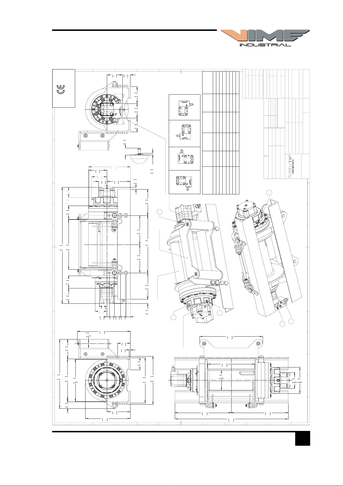
1.4.3 EPHL 100 FN CE TECHNICAL DATA
1.4.4 EPHL 100 FN CE WINCH PERFORMANCE CHARTS AT THE 1ST LAYER
0
2.000
4.000
6.000
8.000
10.000
12.000
50 100 150 200
PRESSIONE DI LAVORO [Bar]
0,00
2,00
4,00
6,00
8,00
10,00
12,00
20 40 60 75
ALIMENTAZIONE OLIO [litri/min]
RATIO LAYER LINE PULL ON [KGF]
ROPE 15 MM
1/22,69
1 10.000
2 8.550
3 7.460
4 6.600
5 5.900
ROPE 16 MM
1/22,69
1 10.000
2 8.470
3 7.350
4 6.490
5 5.800
LINE PULL [KGF]
LINE SPEED [MT/MIN]
OIL
SUPPLY
[LT/MIN]
DRUM
REVOLUTION
[RPM]
LINE SPEED PER LAYER [MT/MIN]
1 2 3 4 5
ROPE 15 MM
40 10,0 5,6 6,5 7,4 8,3 9,1
60 15,7 8,8 10,1 11,7 13 14,5
75 20,0 11,1 13 15 16,7 18,6
40 10,0 5,6 6,6 7,6 8,6 9,6
60 15,7 8,8 10,3 11,9 13,5 15,1
75 20,0 11,1 13,2 15,2 17,2 19,2
ROPE 16 MM
WIRE ROPE QUANTITY ON LAYER (DRUM LENGTH EPHL FN= 373 MM)
LAYER
DRUM
DIAMETER
[MM]
WIRE ROPE
ON LAYER
[MT]
WIRE ROPE
QUANTITY
[MT]
15 MM 16 MM 15 MM 16 MM 15 MM 16 MM
6 327 338 24,5 23,7 113,4 108,5
5 297 306 22,3 21,4 88,9 84,8
4 267 274 20,0 19,2 66,6 63,4
3 237 242 17,8 17,0 46,6 44,2
2 207 210 15,5 14,7 28,8 27,2
1 177 178 13,3 12,5 13,3 12,5
0 162 162 - - - -
LINE SPEED [MT/MIN]
WORKING PRESSURE [BAR] OIL SUPPLY [LT/MIN]
LINE PULL FIRST LAYER [KG]
Ø 162
LAYER
Ø 342
FEATURES EPHL 100 FN CE (160 cc.)
LINE PULL FIRST LAYER 10.000 KGF
LINE SPEED FIRST LAYER 11,1 MT/MIN.
MAX. WORKING PRESSURE 200 BAR
MAX. OIL SUPPLY 75 LT/MIN
MIN. OIL SUPPLY 20 LT/MIN
WIRE ROPE SIZE (EN 14492-1) *15/16 MM
WIRE ROPE MINIMUN BREAKING ROPE (EN 14492-1) 20.000 KG
MAX. WIRE ROPE CAPACITY (EN 14492-1) **80/60 MT
NOTE
Specifications are subject to change without notification and without incurring obliga-
tion. Specifications in this publication are theoretical and may vary depending on hy-
draulic system, environment, etc.
*Wire rope size must be respected. Recommended wire rope min. tensile strength 2160
N/mm². Wire rope minimum breaking load must be at least double of winch max.
pulling capacity.
** Max. wire rope capacity according with EN 14492-1.
WINCH (WITHOUT CABLE) 200
ACCESSORY : ROLLERFAIRLEAD 35
ACCESSORY : CABLE TENSIONER 10
WEIGHT [KG]

Section 1 Safety procedures 9
The Quality is Transparent
1.4.5 EPHL 125 FN CE WINCH DIMENSIONAL DATA
Machinery Directive 2006/42/CE
EN 14492-1
8,5
215
18,5
470
8,5
215
0,6
15
9,1
232
9,4
238
1,4
36
1,7
42
1,9
48
1,7
42
0,7
18
1,4
35
5,0
126
4,0
102
16,1
409
4,3
110
13,0
331
5,7
145
2,7
68
3,2
82
2,6
66
7,3
186
4,7
121
2,4
60
3,7
93
37,4
951
K
14,6
370
15,6
395
3,9
100
3,9
100
0,4
10
13,8
350
13,5
342
7,3
186
6,3
160
2,8
70
16,6
421
2,1
54
22,2
564
14,1
357
35,4
900
6,4
162
14,7
373
8,4
214
17,6
447
17,8
453
19,7
500
5,2
131
2,5
63
4,8
123
4,4
113
4,7
120
5,4
137
OVERCENTER VALVE POSITION*
V6
(ON REQUEST)
(STANDARD)
V
V9 V3
(ON REQUEST) (ON REQUEST)
V1
V2
3
E - Air Clutch Port
Engages/Disengages
Drum
2
1
C
Hydraulic
Motor
Cable Tensioner
Heavy Duty
Roller Fairlead
0,2
5
E(Y)
K
0,8
21
E(X)
*AT THE MOMENT OF ORDER IS POSSIBILE REQUEST THE
OVERCENTER VALVE PORTS ORIENTED ACCORDING TO THE LAY
OUT ABOVE. IF NOT SPECIFIED, THE WINCH WILL BE SUPPLIED
WITH THE OVERCENTER VALVE PORTS ORIENTED AS PER OUR
STANDARD CONFIGURATION V6.
WINCH ORDERING
CODE
AIR CLUTCH
(STANDARD)
MANUAL
CLUTCH
(ON REQUEST)
HEAVY DUTY
ROLLER FAIRLEAD
(ON REQUEST)
CABLE
TENSIONER
(ON REQUEST)
OVER CENTER
VALVE POSITION*
( STANDARD V6)
EPHLFN125U20EAV6
XX
EPHLFN125U20EAPV6
XXX
EPHLFN125U20EAGV6
XX X
EPHLFN125U20EAGPV6
XXXX
EPHLFN125U20EV6
XX
EPHLFN125U20EPV6
XXX
EPHLFN125U20EGV6
XX X
EPHLFN125U20EGPV6
XXX X
F
8
E
D
C
B
A
G
H
J
K
L
M
7
6
5
4
3
2
1
9
10
11
12
13
14
15
9
1
2
3
4
5
6
7
8
10
11
G
B
C
D
E
F
H
J
DATA
19/09/2016
EPHLFN125U20EAGPV6
EPHL 125 FN
COD.
1:3.5
14,5 Mt./Min.
9,2 Mt./Min.
75 Lt./Min.
G 1/4
G 3/8
G 3/8
200 cc
1/22,69
200 Kg
G 1/8
G 1/4
G 3/4
G 3/4
200 bar
373 mm
10 Kg
35 Kg
12500 Kg
Funo - Bologna (Italy)
www.vimeindustrial.com
C
CASE DRAIN
V2
IN LET
PLANETARY
GEAR
V1
OUT LET
The Quality is Transparent
RETURN
SPRING
Air-operated
VIME Industrial :
reserves the right to improve its
products through changes in designed or materials
as it may seem desiderablewithout notice
Pulling capacity
Modification
Date
Gear ratio
Orbital hydr. motor
Working pressure
Drum size
WINCH
GROUP
WINCH
MODEL
E (X)
DISENGAGED
DANGEROUS:
Do not use winch to
lift support or transport personnel.
Drum clutch
Max.Oil flow
Speed Line - first layer
Speed Line - top layer
E (Y)
ENGAGED
CONNECTIONS
PLUGS
1.Fill
2.Level
3.Drain
SCALE
WEIGHTS
Winch (without oil)
Heavy-duty
Roller fairlead
Cable tensioner

Section 1 Safety procedures 10
The Quality is Transparent
1.4.6 EPHL 125 FN CE TECHNICAL DATA
1.4.7 EPHL 125 FN CE WINCH PERFORMANCE CHARTS AT THE 1ST LAYER
0,00
2,00
4,00
6,00
8,00
10,00
20 40 60 75
ALIMENTAZIONE OLIO [litri/min]
0
2.000
4.000
6.000
8.000
10.000
12.000
14.000
50 100 150 200
PRESSIONE DI LAVORO [Bar]
RATIO LAYER LINE PULL [KGF]
ROPE 15 MM
22,69:1
1 12.500
2 10.680
3 9.330
4 8.280
5 7.440
ROPE 18 MM
22,69:1
1 12.500
2 10.410
3 8.920
4 7.810
5 6.940
LINE PULL [KGF]
LINE SPEED [MT/MIN]
OIL
SUPPLY
[LT/MIN]
DRUM
REVOLUTION
[RPM]
LINE SPEED PER LAYER [MT/MIN]
1 2 3 4 5
ROPE 15 MM
40 8,1 4,5 5,1 5,9 6,7 7,3
60 12,6 7,1 8,1 9,4 10,6 11,6
75 16 9,1 10,4 12,0 13,5 15,0
40 8,1 4,6 5,5 6,4 7,3 8,2
60 12,6 7,2 8,6 10 11,4 12,8
75 16 9,2 10,9 12,7 14,5 16,3
ROPE 18 MM
WIRE ROPE QUANTITY ON LAYER (DRUM LENGTH EPHL FN= 373 MM)
LAYER
DRUM
DIAMETER
[MM]
WIRE ROPE
ON LAYER
[MT]
WIRE ROPE
QUANTITY
[MT]
15 MM 18 MM 15 MM 18 MM 15 MM 18 MM
6 327 - 24,5 - 113,4 -
5 297 324 22,3 20,1 88,9 78,1
4 267 288 20,0 17,8 66,6 58
3 237 252 17,8 15,6 46,6 40,1
2 207 216 15,5 13,4 28,8 24,5
1 177 180 13,3 11,2 13,3 11,2
0 162 162 - - - -
LINE SPEED [MT/MIN]
WORKING PRESSURE [BAR] OIL SUPPLY [LT/MIN]
LINE PULL FIRST LAYER [KG]
Ø 162
LAYER
Ø 342
FEATURES EPHL 125 FN CE (200 cc.)
LINE PULL FIRST LAYER 12.500 KGF
LINE SPEED FIRST LAYER 9,2 MT/MIN.
MAX. WORKING PRESSURE 200 BAR
MAX. OIL SUPPLY 75 LT/MIN
MIN. OIL SUPPLY 20 LT/MIN
WIRE ROPE SIZE (EN 14492-1) *15/18 mm
WIRE ROPE MINIMUN BREAKING ROPE (EN 14492-1) 25.000 KG
MAX. WIRE ROPE CAPACITY (EN 14492-1) **80/55 MT
NOTE
Specifications are subject to change without notification and without incurring obliga-
tion. Specifications in this publication are theoretical and may vary depending on hy-
draulic system, environment, etc.
*Wire rope size must be respected. Recommended wire rope min. tensile strength 2160
N/mm². Wire rope minimum breaking load must be at least double of winch max.
pulling capacity.
** Max. wire rope capacity according with EN 14492-1.
WINCH (WITHOUT CABLE) 200
ACCESSORY : ROLLERFAIRLEAD 35
ACCESSORY : CABLE TENSIONER 10
WEIGHT [KG]

Section 1 Safety procedures 11
The Quality is Transparent
1.4.8 EPHL 150 FN CE WINCH DIMENSIONAL DATA
Machinery Directive 2006/42/CE
EN 14492-1
8,5
215
18,5
470
8,5
215
0,6
15
9,1
232
9,4
238
1,7
44
1,7
42
1,9
48
1,7
42
0,7
18
1,8
44
5,3
135
4,0
102
16,1
409
4,3
110
13,3
339
5,7
145
2,7
68
3,2
82
2,6
66
7,6
194
4,7
121
2,4
60
3,7
93
37,8
960
K
14,7
374
15,7
399
4,3
110
4,3
110
0,5
12
13,8
350
13,5
342
7,6
194
2,4
61
6,3
160
22,5
571
2,8
70
16,5
420
14,4
365
35,4
900
6,4
162
14,7
373
8,4
214
17,6
447
17,8
453
20,5
521
5,2
131
19,7
500
2,8
71
4,8
123
4,5
115
4,7
120
5,5
139
OVERCENTER VALVE POSITION*
V6
(ON REQUEST)
(STANDARD)
V
V9 V3
(ON REQUEST) (ON REQUEST)
V1
V2
3
E - Air Clutch Port
Engages/Disengages
Drum
2
1
C
Hydraulic
Motor
Cable Tensioner
Heavy Duty
Roller Fairlead
0,2
5
E(Y)
K
0,8
21
E(X)
*AT THE MOMENT OF ORDER IS POSSIBILE REQUEST THE
OVERCENTER VALVE PORTS ORIENTED ACCORDING TO THE LAY
OUT ABOVE. IF NOT SPECIFIED, THE WINCH WILL BE SUPPLIED
WITH THE OVERCENTER VALVE PORTS ORIENTED AS PER OUR
STANDARD CONFIGURATION V6.
WINCH ORDERING
CODE
AIR CLUTCH
(STANDARD)
MANUAL
CLUTCH
(ON REQUEST)
HEAVY DUTY
ROLLER FAIRLEAD
(ON REQUEST)
CABLE
TENSIONER
(ON REQUEST)
OVER CENTER
VALVE POSITION*
( STANDARD V6)
EPHLFN150U25EAV6
XX
EPHLFN150U25EAPV6
XXX
EPHLFN150U25EAGV6
XX X
EPHLFN150U25EAGPV6
XXXX
EPHLFN150U25EV6
XX
EPHLFN150U25EPV6
XXX
EPHLFN150U25EGV6
XX X
EPHLFN150U25EGPV6
XXX X
F
8
E
D
C
B
A
G
H
J
K
L
M
7
6
5
4
3
2
1
9
10
11
12
13
14
15
9
1
2
3
4
5
6
7
8
10
11
G
B
C
D
E
F
H
J
DATA
19/09/2016
EPHLFN150U25EAGPV6
EPHL 150FN
COD.
1:3.5
11 Mt./Min.
7 Mt./Min.
75 Lt./Min.
G 1/4
G 3/8
G 3/8
250 cc
1/22,69
210 Kg
G 1/8
G 1/4
G 3/4
G 3/4
200 bar
373 mm
10 Kg
42 Kg
15000 Kg
Funo - Bologna (Italy)
www.vimeindustrial.com
C
CASE DRAIN
V2
IN LET
PLANETARY
GEAR
V1
OUT LET
The Quality is Transparent
RETURN
SPRING
Air-operated
VIME Industrial :
reserves the right to improve its
products through changes in designed or materials
as it may seem desiderablewithout notice
Pulling capacity
Modification
Date
Gear ratio
Orbital hydr. motor
Working pressure
Drum size
WINCH
GROUP
WINCH
MODEL
E (X)
DISENGAGED
DANGEROUS:
Do not use winch to
lift support or transport personnel.
Drum clutch
Max.Oil flow
Speed Line - first layer
Speed Line - top layer
E (Y)
ENGAGED
CONNECTIONS
PLUGS
1.Fill
2.Level
3.Drain
SCALE
WEIGHTS
Winch (without oil)
Heavy-duty
Roller fairlead
Cable tensioner

Section 1 Safety procedures 12
The Quality is Transparent
1.4.9 EPHL 150 FN CE TECHNICAL DATA
1.4.10 EPHL 150 FN CE WINCH PERFORMANCE CHARTS AT THE 1ST LAYER
0
2.000
4.000
6.000
8.000
10.000
12.000
14.000
16.000
50 100 150 200
PRESSIONE DI LAVORO [Bar]
0,00
1,00
2,00
3,00
4,00
5,00
6,00
7,00
8,00
20 40 60 75
ALIMENTAZIONE OLIO [litri/min]
RATIO LAYER LINE PULL [KGF]
ROPE 18 MM
22,69:1
1 15.000
2 12.500
3 10.700
4 9.370
5 8.300
-
-
- -
- -
- -
- -
- -
LINE PULL [KGF]
LINE SPEED [MT/MIN]
OIL
SUPPLY
[LT/MIN]
DRUM
REVOLUTION
[RPM]
LINE SPEED PER LAYER [MT/MIN]
1 2 3 4 5
ROPE 18 MM
40 5,8 3,3 3,9 4,6 5,2 5,9
60 9,4 5,3 6,4 7,4 8,5 9,6
75 12,1 7 8,2 9,6 11 12,3
- - - - - - -
- - - - - - -
- - - - - - -
-
WIRE ROPE QUANTITY ON LAYER (DRUM LENGTH EPHL FN= 373 MM)
LAYER
DRUM
DIAMETER
[MM]
WIRE ROPE
ON LAYER
[MT]
WIRE ROPE
QUANTITY
[MT]
18 MM - 18 MM - 18 MM -
6 - - - - - -
5 324 - 20,1 - 78,1 -
4 288 - 17,8 - 58 -
3 252 - 15,6 - 40,1 -
2 216 - 13,4 - 24,5 -
1 180 - 11,2 - 11,2 -
0 162 - - - - -
LINE SPEED [MT/MIN]
WORKING PRESSURE [BAR] OIL SUPPLY [LT/MIN]
LINE PULL FIRST LAYER [KG]
Ø 162
LAYER
Ø 342
FEATURES EPHL 150 FN CE (250 cc.)
LINE PULL FIRST LAYER 15.000 KGF
LINE SPEED FIRST LAYER 7 MT/MIN.
MAX. WORKING PRESSURE 200 BAR
MAX. OIL SUPPLY 75 LT/MIN
MIN. OIL SUPPLY 20 LT/MIN
WIRE ROPE SIZE (EN 14492-1) *18 MM
WIRE ROPE MINIMUN BREAKING ROPE (EN 14492-1) 30.000 KG
MAX. WIRE ROPE CAPACITY (EN 14492-1) **55 MT
NOTE
Specifications are subject to change without notification and without incurring obliga-
tion. Specifications in this publication are theoretical and may vary depending on hy-
draulic system, environment, etc.
*Wire rope size must be respected. Recommended wire rope min. tensile strength 2160
N/mm². Wire rope minimum breaking load must be at least double of winch max.
pulling capacity.
** Max. wire rope capacity according with EN 14492-1.
WINCH (WITHOUT CABLE) 210
ACCESSORY : ROLLERFAIRLEAD 42
ACCESSORY : CABLE TENSIONER 10
WEIGHT [KG]

Section 1 Safety procedures 13
The Quality is Transparent
1.4.11 EPHL 165 FN CE WINCH DIMENSIONAL DATA
Machinery Directive 2006/42/CE
EN 14492-1
8,5
215
18,5
470
8,5
215
0,6
15
9,1
232
9,4
238
1,7
44
1,7
42
1,9
48
1,7
42
0,7
18
2,2
55
5,8
146
4,0
102
16,1
409
4,3
110
13,3
339
5,7
145
2,7
68
3,2
82
2,6
66
7,6
194
4,7
121
2,4
60
3,7
93
38,2
971
K
14,7
374
15,7
399
4,3
110
4,3
110
0,5
12
13,8
350
13,5
342
7,6
194
2,4
61
22,5
571
6,3
160
2,8
70
16,5
420
14,4
365
35,4
900
6,4
162
14,7
373
8,4
214
17,6
447
17,8
453
20,5
521
5,2
131
19,7
500
2,8
71
4,8
123
4,5
115
4,7
120
5,5
139
OVERCENTER VALVE POSITION*
V6
(ON REQUEST)
(STANDARD)
V
V9 V3
(ON REQUEST) (ON REQUEST)
V1
V2
3
E - Air Clutch Port
Engages/Disengages
Drum
2
1
C
Hydraulic
Motor
Cable Tensioner
Heavy Duty
Roller Fairlead
0,2
5
E(Y)
K
0,8
21
E(X)
*AT THE MOMENT OF ORDER IS POSSIBILE REQUEST THE
OVERCENTER VALVE PORTS ORIENTED ACCORDING TO THE LAY
OUT ABOVE. IF NOT SPECIFIED, THE WINCH WILL BE SUPPLIED
WITH THE OVERCENTER VALVE PORTS ORIENTED AS PER OUR
STANDARD CONFIGURATION V6.
WINCH ORDERING
CODE
AIR CLUTCH
(STANDARD)
MANUAL
CLUTCH
(ON REQUEST)
HEAVY DUTY
ROLLER FAIRLEAD
(ON REQUEST)
CABLE
TENSIONER
(ON REQUEST)
OVER CENTER
VALVE POSITION*
( STANDARD V6)
EPHLFN165U31EAV6
XX
EPHLFN165U31EAPV6
XXX
EPHLFN165U31EAGV6
XX X
EPHLFN165U31EAGPV6
XXXX
EPHLFN165U31EV6
XX
EPHLFN165U31EPV6
XXX
EPHLFN165U31EGV6
XX X
EPHLFN165U31EGPV6
XXX X
F
8
E
D
C
B
A
G
H
J
K
L
M
7
6
5
4
3
2
1
9
10
11
12
13
14
15
9
1
2
3
4
5
6
7
8
10
11
G
B
C
D
E
F
H
J
DATA
19/09/2016
EPHLFN165U31EAGPV6
EPHL 165FN
COD.
1:3.5
8,9 Mt./Min.
5,6 Mt./Min.
75 Lt./Min.
G 1/4
G 3/8
G 3/8
315 cc
1/22,69
210 Kg
G 1/8
G 1/4
G 3/4
G 3/4
180 bar
373 mm
10 Kg
42 Kg
16500 Kg
Funo - Bologna (Italy)
www.vimeindustrial.com
C
CASE DRAIN
V2
IN LET
PLANETARY
GEAR
V1
OUT LET
The Quality is Transparent
RETURN
SPRING
Air-operated
VIME Industrial :
reserves the right to improve its
products through changes in designed or materials
as it may seem desiderablewithout notice
Pulling capacity
Modification
Date
Gear ratio
Orbital hydr. motor
Working pressure
Drum size
WINCH
GROUP
WINCH
MODEL
E (X)
DISENGAGED
DANGEROUS:
Do not use winch to
lift support or transport personnel.
Drum clutch
Max.Oil flow
Speed Line - first layer
Speed Line - top layer
E (Y)
ENGAGED
CONNECTIONS
PLUGS
1.Fill
2.Level
3.Drain
SCALE
WEIGHTS
Winch (without oil)
Heavy-duty
Roller fairlead
Cable tensioner

Section 1 Safety procedures 14
The Quality is Transparent
1.4.12 EPHL 165 FN CE TECHNICAL DATA
1.4.13 EPHL 165 FN CE WINCH PERFORMANCE CHARTS AT THE 1ST LAYER
0
5.000
10.000
15.000
20.000
60 100 140 180
PRESSIONE DI LAVORO [Bar]
0,00
1,00
2,00
3,00
4,00
5,00
6,00
20 40 60 75
ALIMENTAZIONE OLIO [litri/min]
RATIO LAYER LINE PULL [KGF]
ROPE 18 MM
22,69:1
1 16.500
2 13.750
3 11.780
4 10.300
5 9.160
-
-
- -
- -
- -
- -
- -
LINE PULL [KGF]
LINE SPEED [MT/MIN]
OIL
SUPPLY
[LT/MIN]
DRUM
REVOLUTION
[RPM]
LINE SPEED PER LAYER [MT/MIN]
1 2 3 4 5
ROPE 18 MM
40 4,9 2,8 3,4 3,9 4,5 5
60 7,8 4,4 5,3 6,1 7 7,9
75 9,9 5,6 6,7 7,8 8,9 10,1
- - - - - - -
- - - - - - -
- - - - - - -
-
WIRE ROPE QUANTITY ON LAYER (DRUM LENGTH EPHL FN= 373 MM)
LAYER
DRUM
DIAMETER
[MM]
WIRE ROPE
ON LAYER
[MT]
WIRE ROPE
QUANTITY
[MT]
18 MM - 18 MM - 18 MM -
6 - - - - - -
5 324 - 20,1 - 78,1 -
4 288 - 17,8 - 58 -
3 252 - 15,6 - 40,1 -
2 216 - 13,4 - 24,5 -
1 180 - 11,2 - 11,2 -
0 162 - - - - -
LINE SPEED [MT/MIN]
WORKING PRESSURE [BAR] OIL SUPPLY [LT/MIN]
LINE PULL FIRST LAYER [KG]
Ø 162
LAYER
Ø 342
FEATURES EPHL 165 FN CE (315 cc.)
LINE PULL FIRST LAYER 16.500 KGF
LINE SPEED FIRST LAYER 5,6 MT/MIN.
MAX. WORKING PRESSURE 180 BAR
MAX. OIL SUPPLY 75 LT/MIN
MIN. OIL SUPPLY 20 LT/MIN
WIRE ROPE SIZE (EN 14492-1) *18 MM
WIRE ROPE MINIMUN BREAKING ROPE (EN 14492-1) 33.000 KG
MAX. WIRE ROPE CAPACITY (EN 14492-1) **55 MT
NOTE
Specifications are subject to change without notification and without incurring obliga-
tion. Specifications in this publication are theoretical and may vary depending on hy-
draulic system, environment, etc.
*Wire rope size must be respected. Recommended wire rope min. tensile strength 2160
N/mm². Wire rope minimum breaking load must be at least double of winch max.
pulling capacity.
** Max. wire rope capacity according with EN 14492-1.
WINCH (WITHOUT CABLE) 210
ACCESSORY : ROLLERFAIRLEAD 42
ACCESSORY : CABLE TENSIONER 10
WEIGHT [KG]

2
REEL IN ROTATION
SENSO DI AVVOLGIMENTO
A
3
1
-
TIRARE
-RILA
S
CIAR
E
-
TIRARE
-ABWI
C
KEL
N
-DREHEN 9
0
-EIN
G
ERA
S
TE
T
-ABWI
C
KEL
N
-DREHEN 9
0
-EIN
G
ERA
S
TE
T
1 - L'INNE
S
T
O
DEVE E
SS
ERE T
O
TALMENTE I
N
-
2 - N
O
N DI
S
IN
S
ERIRE IL VERRICELL
O
SO
TT
O
CARIC
O.
-
RICELL
O
N
O
N
È
È
IN
USO.
È
IN TRAZI
O
NE
.
5
- N
O
N
SU
PERARE LA MAX
.
CAPACI
T
À
DI
TIR
O
DEL VERRICELL
O.
-
VARE
O
RIM
UO
VERE PER
SO
NE
.
-
C
O
DELLA F
U
NE
SU
L TAMB
U
R
O
N
O
N
È
È
IN
G
RAD
O
DI
SO
PP
O
RTARE IL CARIC
O.
NDI
G
EIN
G
EK
U
PPELT
S
EIN
.
2
-
W
Ä
WW
HREND DER BEWEGUNG DER SEILWINDE DARF
Ä
Ä
3
- WENN DIE SEILWINDE NICHT BENUTZT WIRD
,
IST SI
E
Ä
Ä
T,
TRAGEMITTEL ODER DIE LAS
T
GEF
Ä
F
F
HRDET WERDEN KANN.
Ä
Ä
5
-
Ü
BERSCHREITEN SIE NIEMALS DIE ZUGKRAFT DER
Ü
Ü
S
EILWINDE
!
6
- DIE
S
E
S
EILWINDE DARF NICHT Z
U
M HEBEN V
ON
LASTEN ODER PERSONEN BENUTZT WERDEN
.
Ü
SSEN NOCH MINDESTENS
Ü
Ü
A
U
FNEHMEN Z
U
K
Ö
K
K
NNEN, DA DIE SEILBEFESTIGUNG
Ö
Ö
ALLEIN DAF
Ü
FF
S
I
S
TEMA DI INNE
S
T
O
MAN
U
AL
E
FREILA
U
F
S
CHALT
U
N
G
S
ERIE
N
FABRIKN
U
MME
R
ANN
O
DI C
OS
TR
U
ZI
O
N
E
BA
UJ
AH
R
M
O
DELL
O:
TIR
O
MAX
.
-
1
s
tr
a
t
o
F
U
NEC
O
N
S
I
G
LIAT
A
S
EILD
U
RCHME
SS
E
R
PRE
SS
I
O
NEMAX
.
MAX
.
DR
U
C
K
ATTENZI
O
NE
:
EPH
K
G
Ø
MM
BAR
LEGGEREATTENTAMENTE LE ISTRUZIO
-
NIPRIMA DI
O
PERARE
.
Ä
LTI
G
Z
U
LE
S
EN
.
/
DATI TECNICI
/
T
ECHNI
S
CHE DATE
N
A decal (1) onto the top of the gear housing
gives: winch model, max. pulling capacity at
the first layer, wire rope diameter, max.
working pressure, serial number and year of
built. A yellow sticker (2) onto the roller fair-
lead, warns about rotating parts.
IMPORTANT
When ordering replacement parts or
contact VIME Industrial customers
service, please gives winch model, serial
number and manufacture year.
If not specified, winch is supplied with
counter clockwise cable rotation on the drum
called “ A Rotation”. A label (3) located on the
Section 1 Safety procedures
gear housing indicates the spooling direction
of the cable.
IMPORTANT
Check if all decals and labels have been
fitted and as a maintenance, if decals ore
labels are damaged or unreadable,
replace it.
1.5 WINCH DECALS. SAFETY ADVICES
1.6 CONDITIONS OF SALE
The winch, except special customer require-
ments is delivered assembled and tested.
Wire rope and hook are not included in the
standard winch version, only if required are
included in the commitment. At the delivery,
open carefully the packing. Inspect the winch
and see if it is free from defects.
IMPORTANT
In case of damages or missing parts,
inform carrier immediately.
15
PICT.2
The Quality is Transparent

The standard packaging, if supplied, and
unless otherwise agreed, is not rainproof and
is intended for shipping by ground and not
sea, and for areas which are under cover and
not humid.
Section 1 Safety procedures
IMPORTANT
Dispose of packaging materials as
stipulated by the applicable legislation.
The Quality is Transparent
16
1.6.1 PACKAGING
1.6.2 PACKAGING ILLUSTRATION
The Quality is Transparent
PICT.3
NOTE
Winches on pallet are wrapped with plastic film. About its rainproof capacity, refer
what indicated above.

Do not operate this winch until you have
carefully read and understand the warnings
operation sections of this manual.
DANGEROUS
When winching is obligatory wear
working gloves.
• Manual or Air Clutch must be fully
engaged before starting the winch.
• Do not disengage manual or air clutch
under load.
• Do not exceed maximum line pull
ratings.
• In car carrier applications after pulling
vehicle on carrier, be sure to secure
vehicle to carrier bed. Do not maintain
load on winch cable while
transporting vehicle. Do not use winch
as a tie down.
Section 1 Safety procedures
WARNING
Do not use winch to lift, support or
otherwise transport personnel.
DANGEROUS
A minimum of 5 wraps of cable around
drum barrel is recommended.
DANGEROUS
Stand clear of cable while pulling. A
broken cable can cause serious injury or
death. Do not try to guide cable. Do not
disengage clutch under load.
1.7 SAFETY PROCEDURES
17
The Quality is Transparent
1
2
3
4
5

2.2 WINCH MOUNTING
2.1 ROAD TRAFFIC
Winches mod. EPHFN have been designed to
be mounted on vehicles frame in compliance
with regulation. Many countries require to keep
up to date with traffic card. Do not drive
Section 2 Mounting
vehicle not in compliance with regulation or
not up dated traffic card.
SECTION 2
MOUNTING
The winch base angles should be securely
mounted to the vehicle frame in a manner
acceptable to the vehicle manufacturer. It is
responsibility of the person(s) installing the
winch to make certain that the winch is
secured to the vehicle with equivalent or
greater strength capscrews then VIME used to
secure the winch to the base angles (1). The
winch must be fitted horizontally to give best
lubrication and securely mounted on a
surface who can resist to the winch pulling,
without having any flex within the base and
the winch while in use.
18
PICT. 4 Standard base angles mounting are delivered fitted on winch body:
Dimension:
mm - [ inch ] 100x100x10 - [ 3,9x3,9x0,4 ] for EPHL 100/125 FN CE
mm - [ inch ] 110x110x12 - [ 4,3x4,3x0,5 ] for EPHL 150/165 FN CE
The Quality is Transparent
NOTE
The number 4 mounting angles holes on each side shown in pict.4, are not present at the delivery.
Are shown in pict.4 just as demonstration. All others holes are for the accessories mounting.
IMPORTANT
Winch is built up for different model of
trucks. Holes on the mounting angles are
not present, installer will make it, taking
in consideration the right winch position
on truck.
Winch can be mounted without the mounting
angles.
0,4
10
3,9
100
3,9
100
4,3
110
4,3
110
0,5
12
1
1

Section 2 Mounting 19
The Quality is Transparent
Winch must no be mounted directly onto the
vehicle chassis, it should be better mounting a
frame adapter brackets who can resist to the
winch pulling. Mounting hole locations, size
and thread depth are specified for every winch
(pict.5).
WARNING
Winch must no be mounted directly onto
the vehicle chassis.
PICT.5
WARNING
All mounting holes patterns should be
used to bolt the winch.
WARNING
Use the mounting hole locations provided
on the dimensional data, pair dimensions
of surfaces must be respected. A wrong
winch mounting reduce winch perform-
ance, cause overheating, excessive wear
and could damage the winch.
238 232
470
45
42 48 42
45
22 132 18
230,2
350
78 78
172
30
N.16XM20
Lmax
L
Model L[MM] Lmax[MM] (Pneumatic clutch version)
EPHL 100 FN CE 243,5 943,7
EPHL 125 FN CE 250,5 950,7
EPHL 150 FN CE 259,5 959,7
EPHL 165 FN CE 270,5 970,7
This manual suits for next models
3
Table of contents
Other VIME INDUSTRIAL Winch manuals
Popular Winch manuals by other brands

Westfalia
Westfalia Electric Winch Original instructions

Champion Power Equipment
Champion Power Equipment EWL5000K Assembly & operating instructions

Tractel
Tractel Carol TR Series Operation and maintenance manual

Eastbound
Eastbound MotoWinch 1707001 operating instructions

TREX
TREX TB75 user manual

Comeup
Comeup DV-18 manual