Orvea Italwinch ACHILL User manual


VI PREGHIAMO DI LEGGERE ATTENTAMENTE LE ISTRUZIONI D'USO E DI MONTAGGIO DEL PRESENTE
MANUALE PRIMA DI OPERARE E INSTALLARE L' ARGANO
INSTALLAZIONE
3
MATERIALE PRESENTE NELLA CONFEZIONE:
Argano completo di COPERTURA, motoriduttore, teleruttore/teleinvertitori, viterie per
l'assemblaggio, dima di foratura, manuale d'uso e installazione.
ATTREZZI NECESSARI PER L'INSTALLAZIONE:
Trapano con punta Ø9, chiave esagonale 13mm, Chiave Brugola 8,cacciavite stella, silicone.
REQUISITI PER L'INSTALLAZIONE:
L'Argano può essere posizionato in qualsiasi punto sia in verticale che in orrizzontale, una volta individuata la
posizione per il montaggio verificare che la superfice d'appoggio sia più piana possibile, nel caso contrario levigare
opportunamente. E' IMPORTANTE CHE IL PUNTO IN CUI ABBIATE DECISO DI FISSARE IL SOLLEVATORE SIA ADATTO
A RESISTERE AL TIRO DEL SOLLEVATORE STESSO, ONDE EVITARE GRAVI DANNI .
-Installare sempre un appropriato interruttore magneto termico per proteggere il circuito e il motore elettrico da
surriscaldamenti o danni.
-Tutta la parte elettrica (motore, teleruttore, centraline) va montata al riparo da schizzi o getti d'acqua.
PROCEDURA DI MONTAGGIO:
Una volta stabilita la posizione di montaggio praticare i fori con la dima fornita a corredo,svitare le 2 viti poste sotto
la campana e sfilare la copertura, siliconare il perimetro sottostante all'Argano, far passarei cavi e i tiranti attraverso
i fori praticati precedentemente , fissare l' Argano serrando i dadi sui prigionieri (i tiranti hanno una lunghezza
standar che permette di fissarli ad una parete di spessore min di 18mm e max di 30mm), togliere il silicone in eccesso,
rimontare la copertura fissando le 2 viti tolte precedentemente. Collegare il motore con gli appositi cavi provenienti
dal teleruttore (togliere tensione prima di operare sulla parte elettrica).
Togliere la rondella di copertura, sfilare il perno, allogiare l'asola della cinghia in prossimità del foro sede perno,
rimontare il perno e riavvitare tappo, avvolgere la cinghia.
ATTENERSI ALLO SPESSOR
E
INDICATO IN TABELLA
SILICONE

LISTA RICAMBI
LISTA RICAMBI ACHILL
3
6
5
100146
100104
100103
CODICE
RIDUTTORE CON STAFFA1
KIT FISSAGGIO MOTORE1
LINGUETTA 500W1
4
3
2A
POS. Q.TA DENOMINAZIONE
100102MOTORE 500W
11A
100148LINGUETTA 800W
1
2B
LISTA RICAMBI ARGANO
2
4
MOTORE 800W 100101
11B
9
100253DADO M845
100106RONDELLA46
100140VITE TSEI M6 X 302
7
100141SPINA D8 X67
1
8
9 100111CHIAVETTA 6X40
2
7
7
8
18
10 1000501COPERTURA1
1000504
1000428
CODICE
RONDELLA RIDUTTORE1
SEEGER RAGGIATO SP3113
POS. Q.TA DENOMINAZIONE
1000502RONDELLA CAMPANA
111
100113SEEGER
114
ALBERO 100503
112
100142
VITE TEI M8X70
4
100143VITE TBEI M5X102
100147CAMPANA1
15
11
12
1314
15
16
17
10
1
16
17
18
LISTA RICAMBI ARGANO
5
LA POSIZIONE 18 COD:100147 COMPRENDE:
COD:1000505 NR 01 PZ
COD:1000506 NR 01 PZ
COD:100157 NR 06 PZ
COD:1000507 NR 01 PZ
LA POSIZIONE 4 COD:100146 COMPRENDE:
COD:1000508 NR 01 PZ
COD:100144 NR 01 PZ
COD:100145 NR 02 PZ
COD:100254 NR 02 PZ

L'argano Italwinch è costruito con materiali resistenti all'ambiente marino, è indispensabile rimuovere
periodicamente i depositi di sale che si formano sulle superfici esterne, per evitare pericolosi fenomeni di
corrosione, lavare con acqua dolce le superfici esterne e asciugare accuratamente.
ATTENZIONE: Il motore elettrico all'interno dell'argano non è stagno; resiste a spruzzi d'acqua ma non ad
immersione
Per le parti elettriche rimuovere l'ossido presente specialmente sui contatti del motore e teleruttore/teleinvertitore
con uno spray per contatti elettrici e cospargerli con grasso.
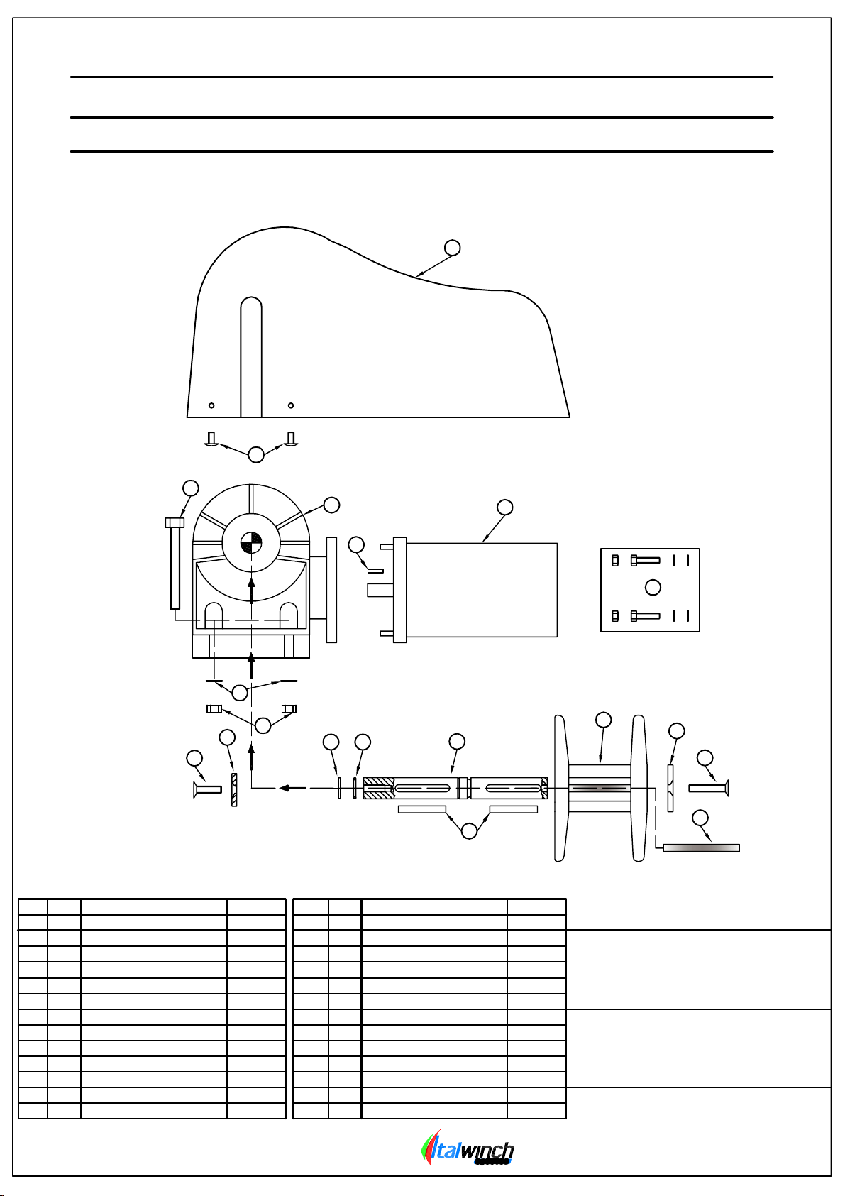
PARTI DI RICAMBIO:
Per identificare un ricambio esaminare il disegno esploso pag 5, ricavarne il codice e la quantità necessaria,
ordinare il ricambio allegando il numero di matricola presente sul salpa-ancora.
6
MANUTENZIONE
ATTENZIONE PRIMA DI COMPIERE OPERAZIONI DI MANUTENZIONE SULL' ARGANO
TOGLIERE COMPLETAMENTE LA TENSIONE A TUTTA LA LINEA .
-EVITARE DI AVVICINARSI O AVVICINARE OGGETTI ALL'ARGANO QUANDO E' IN FUNZIONE, TOGLIERE TENSIONE QUANDO SI
OPERA MANUALMENTE, PERSONE PRESENTI A BORDO POTREBBERO AZIONARE ACCIDENTALMENTE L'ARGANO CON IL
CONTROLLO REMOTO O IL TELECOMANDO.
USO
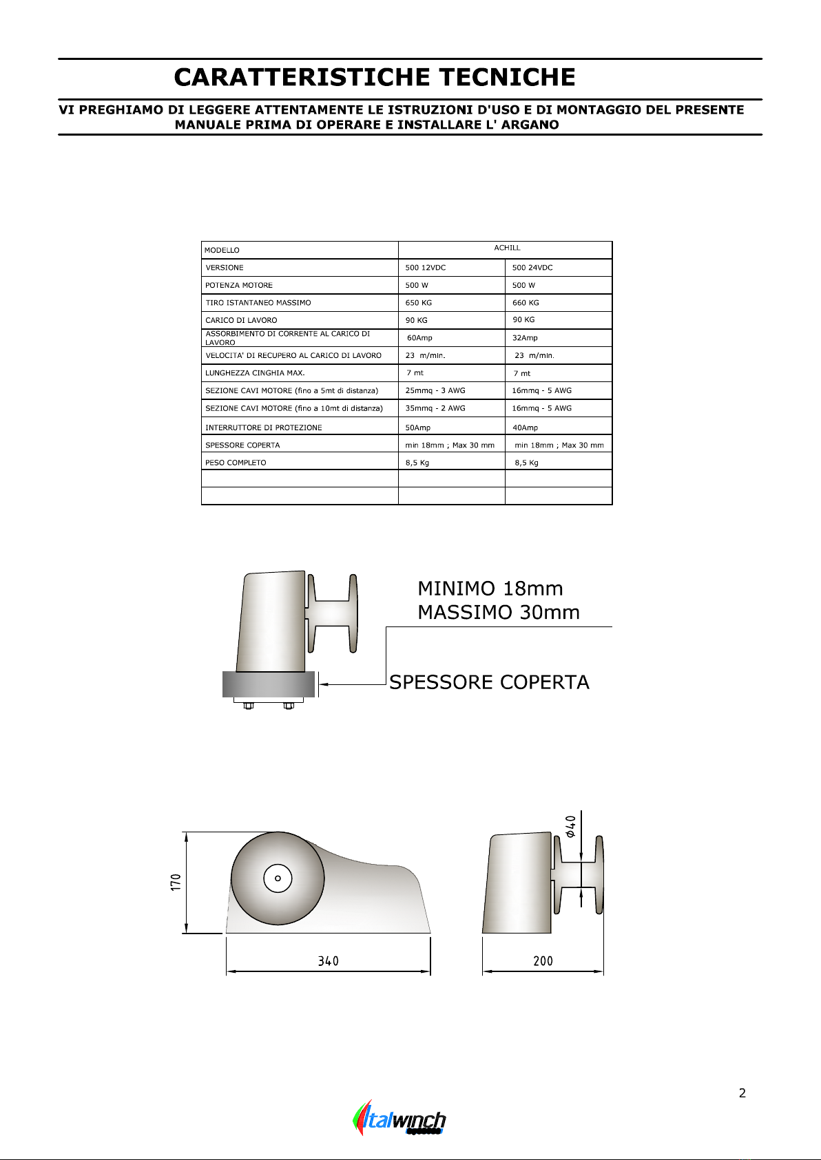
-Gli argani ITALWINCH sono stati esclusivamente realizzati per recuperare TENDER di piccole dimensioni con
carico non superiore al valore indicato nelle tabelle, non sono dei punti di forza, non utilizzare questi apparecchi
per altri usi, l'uso improprio potrebbe causare danni all' argano stesso o a persone.
-La ITALWINCH non si assume nessuna responsabilità per danni diretti o indiretti causati per uso improprio a
persone o cose.
-Disattivare sempre l' argano quando non è in uso per prevenire azionamenti accidentali.
-Non eccedere nel carico, Vi suggeriamo di assistere l'Argano, durante l'operazione di recupero e calata in
mare del TENDER.
-Accertarsi che non vi siano bagnanti o imbarcazioni nelle vicinanze prima di calare o recuperare.
-Installare sempre un appropriato interruttore magneto termico per proteggere il circuito e il motore elettrico da
surriscaldamenti o danni.
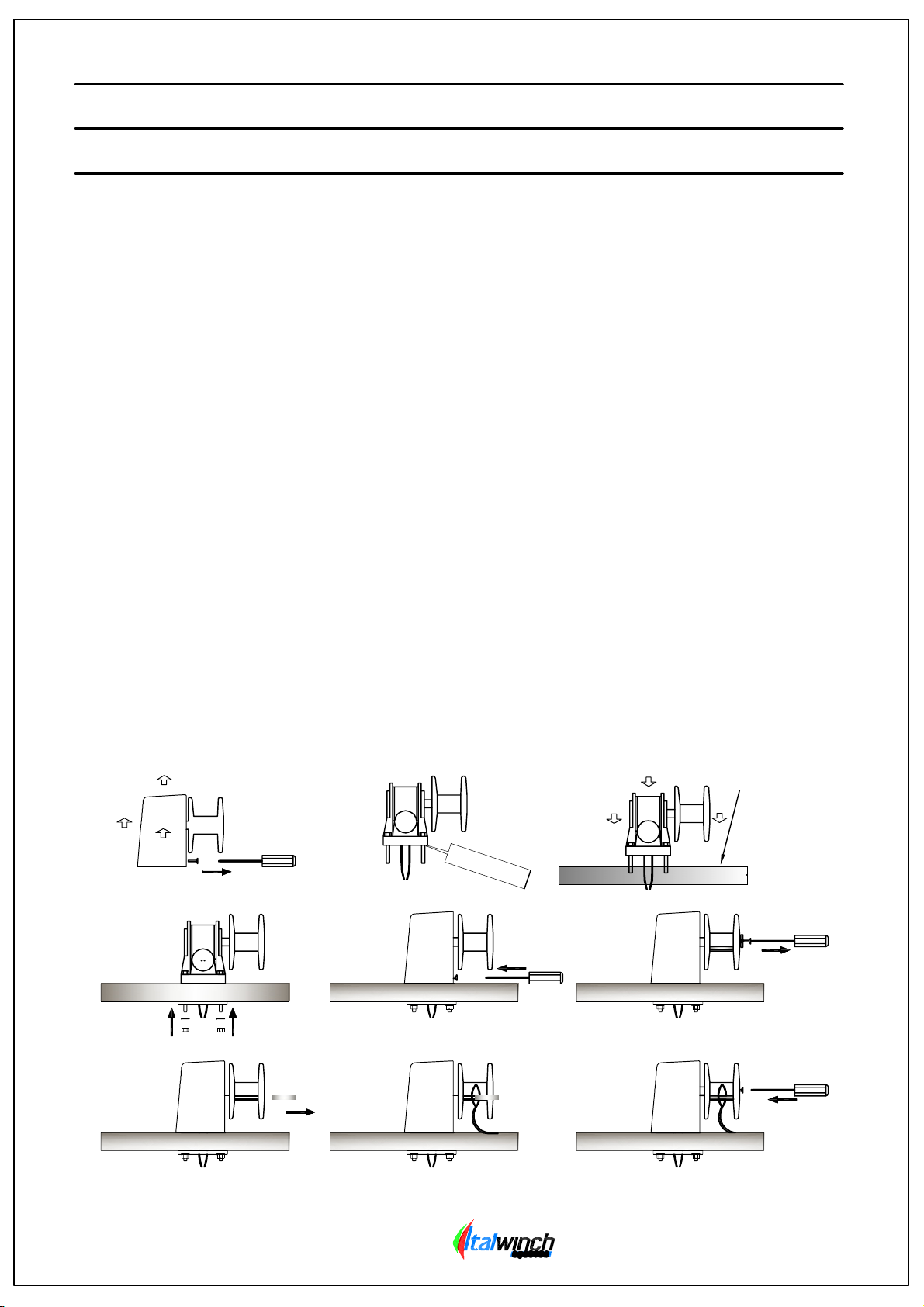
-Bloccare la cinghia con un fermo prima di partire per la navigazione.
-Tenersi sempre lontani durante le operazioni di calata o recupero.
-Se la cinghia si inceppa o si rigira su s'è stessa ripetere l'operazione di calare e recuperare facendo attenzione che
il problema non si ripresenti, se la cinghia non si posiziona in maniera corretta e viene lasciata per lunghi periodi in
questa posizione , potrebbero crearsi delle microrotture , e causare un cedimento della cinghia
stessa durante un utilizzo successivo.


PLEASE CAREFULLY READ THE INSTRUCTIONS FOR USE AND ASSEMBLY CONTAINED IN THIS MANUAL
BEFORE OPERATING AND INSTALLING THE WINCH
INSTALLATION
3
PACKAGE CONTENTS:
Winch complete of coverage, gearmotor, contactors/reversing contactor units, assemply screws, drilling template,
operation and installation manual.
TOOL NEEDED FOR INSTALLATION:
Drilling with a Ø9 bit, 13mm hex wrench, Allen wrench 8, phillips screwdriver anc silicone.
INSTALLATION REQUIREMENTS:
The winch can be positioned at any point, vertically or orizontally, once identified the mounting location , verify
that the surface of support is as flat as possible, otherwise smooth appropriately.
IT'S IMPORTANT THAT THE POINT WHERE YOU HAVE DECIDED TO FIX THE LIFT IS SUITABLE TO RESIST
THE PULL, MAY SERIOUSLY DAMAGE
- Always install an appropriate thermal magnetic breaker to protect the circuit and electric motor from overheating
or damage
- All electrical components (motor, contactor, controllers) must be installed so as to be protected again splashes
or sprays of water
INSTALLATION PROCEDURE:
After selecting the installation position, drill holes using the template provided, unscrew the 2 screws under the bell
and remove the cover, seal the perimeter below the winch, t he cables and tie rods pass through the drilled holes,
fix the winch tightening the nuts on the studs (the bolts are of a length stand that allows you to attach to a wall of
minimum thickness of 18mm and 30mm max) remove the excess silicone, replace the coverage with the two screws
removed earlier. Connect the motor with the appropriate cables from the contactor
(remove power before working on electrical parts).
Remove the cover plate and the pin, housing the slot of the seat belt around the hole pin, replace the bolt and screw
cap, wrap the strap.
ABIDE BY TICHNESS
SPECIFIED IN THE TABLE
SILICONE

LIST OF SPARE PARTS
SPARE PARTS LIST FOR ACHILL
3
6
5
100146
100104
100103
CODE
GEAR WITH BRACKET1
MOTOR FASTENING KIT1
500W KEY1
4
3
2A
POS. Q.TY DESCRIPTION
100102500W MOTOR
11A
100148800W KEY
1
2B
WINCH'S SPARE PARTS
2
4
800W MOTOR 100101
11B
9
100253NUT M845
100106WASHER46
100140SCREW TSEI M6 X 302
7
100141PIN D8 X67
1
8
9 100111KEY 6X40
2
7
7
8
18
10 1000501COVERAGE1
1000504
1000428
CODE
GEAR'S WASHER1
REATING RING RADIUS113
POS. Q.TY DESCRIPTION
1000502DRUM'S WASHER
111
100113REATING RING
114
SHAFT 100503
112
100142
SCREW TEI M8X70
4
100143SCREW TBEI M5X102
100147DRUM1
15
11
12
1314
15
16
17
10
1
16
17
18
WINCH'S SPARE PARTS
5
POSITION No. 18 CODE:100147 INCLUDED:
COD:1000505 No 01 Pc
COD:1000506 No 01 Pc
COD:100157 No 06 Pc
COD:1000507 No 01 Pc
POSITION No 4 CODE:100146 INCLUDED:
COD:1000508 No 01 Pc
COD:100144 No 01 Pc
COD:100145 No 02 Pc
COD:100254 No 02 Pc

Italwinch winch is constructed with materials resistant to marine environment, it is essential to periodically
remove salt deposits that form on the outer surfaces to prevent electrolysis problems, rinse with fresh water
and dry the exterior thoroughly
WARNING: The electric motor to internal's winch is not waterproof, resistant to splashing water but not
submerged
For electrical parts to remove oxide on the contacts of this particular motor and contactor/motor starter
with an electrical contact spray and sprinkle with grease.
SPARE PARTS
In order to identify a spare part, examine the exploded drawing (PG.5), determine the code and the required
quantity and order the spare part, making sure to include the serial number shown on the winch
6
MANTENANCE
WARNING BEFORE PERFORMING ANY MAINTENANCE JOBS ON THE WINCH
COMPLETELY DISCONNECT THE POWER SUPPLY TO THE ENTIRE WINCH LINE.
- DO NOT GO NEAR OR BRING OBJECTS NEAR THE WINCH WHILE IT IS OPERATING. DISCONNECT THE POWER SUPPLY WHEN OPERATING
MANUALLY, ALSO WHEN DISENGAGING THE CLUTCH. PERSONS ON BOARD COULD ACCIDENTALLY ACTIVATE THE ANCHOR WINCH WITH THE
REMOTE OR RADIO CONTROL.
OPERATION
- ITALWINCH Winches ITALWINCH were exclusively designed for small to recover TENDER load does not exceed the
value indicated in the tables they are not strong points. Do not use these devices for other purposes: improper use
could cause damage to the anchor winch or injury to persons.
- ITALWINCH assumes no liability for direct or indirect injury or damage caused to persons or property as a result of
improper use.
- The winch has not been designed to hold the craft in severe weather conditions (gales or storms).
- Always switch off the winch when not in use so as to prevent accidental activation.
- Do not exceed the load limit. We recommend aiding the winch during the operations of recovering and casting the
TENDER.
- Make sure there are no bathers or other craft nearby before casting the anchor.
- Always install an appropriate thermal magnetic breaker to protect the circuit and electric motor from overheating
or damage.
- Secure the chain with a fastener (shackle) before starting your boat trip.
- Always keep hands and feet away from the anchor winch while it is operating.
- If the chain gets caught, switch off the anchor winch and try to free the chain, using extreme caution.
- All electrical components (motor, contactor, controllers) must be installed so as to be protected again splashes or
sprays of water.


This manual suits for next models
2
Table of contents
Other Orvea Winch manuals
Popular Winch manuals by other brands

Warn
Warn 12-A-1D Series installation instructions

BRADEN
BRADEN CH SERIES Installation maintenance and service manual

WARRIOR
WARRIOR 20SPS12 Assembly & operating instructions

Ingersoll-Rand
Ingersoll-Rand Force FH5i Product Maintenance Information

Ultra-tow
Ultra-tow 52810 owner's manual

SuperATV
SuperATV WN-2500 manual