Motor Power Company DUET AD User manual

Installation Guide V1.1
DUET AD

DUET AD Installation Guide Pag. 2
1Index
1Index .......................................................................................................................................... 2
2About this document .................................................................................................................... 4
3General Description ...................................................................................................................... 4
3.1 DUET AD .............................................................................................................................. 4
3.2 Proper use ............................................................................................................................ 5
3.3 Standards and guidelines ....................................................................................................... 5
4Safety instructions........................................................................................................................ 6
5Technical data, accessories ........................................................................................................... 7
5.1 Electrical data........................................................................................................................ 7
5.2 Mechanical data .................................................................................................................... 7
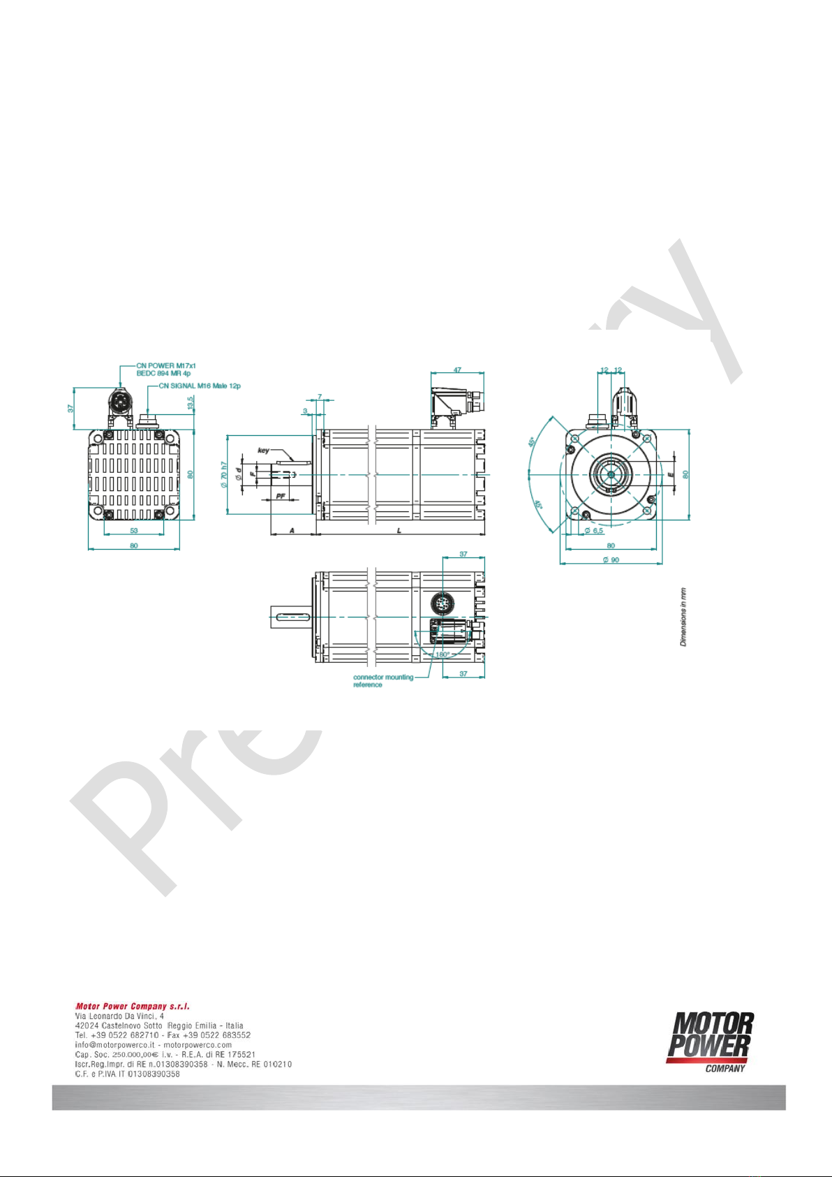
5.3 Dimensions ........................................................................................................................... 8
5.4 DUET AD 1,5 03 .................................................................................................................... 8
5.5DUET AD 2,8 02 .................................................................................................................... 9
5.6 Accessories ........................................................................................................................... 9
6Protective functions.................................................................................................................... 10
6.1 Ballast circuit....................................................................................................................... 10
6.2 Current limitation................................................................................................................. 10
7Installation ................................................................................................................................ 11
8Mechanical assembly .................................................................................................................. 11
8.1 EMI compatibility................................................................................................................. 11
8.2 Ground wire ........................................................................................................................ 12
8.3 Motor power supply ............................................................................................................. 13
8.4 Signal interface supply ......................................................................................................... 15
8.5 Schematic circuit of the digital inputs .................................................................................... 16
8.6 Schematic circuit of the digital outputs .................................................................................. 17
8.7 Maximum cable length and power supply............................................................................... 18
9Connection schematic................................................................................................................. 18
9.1 Schematic circuit for power supply controller ......................................................................... 19
9.2 Connection motor power supply............................................................................................ 20

DUET AD Installation Guide Pag. 3
9.3 Connection signal interface supply ........................................................................................ 21
9.4 Can Open connection Interface............................................................................................. 21
10 Maintenance & Service ............................................................................................................... 22
10.1 Maintenance, taking out of service and disposal ..................................................................... 22
10.2 Service & Support................................................................................................................ 23
Notice:
This guide delivered subject to the following conditions and restrictions: This guide contains proprietary
information belonging to Motor power Company Srl. Such information is supplied solely for the purpose of
assisting users of the DUET AD in its installation and configuration.
The text and graphics included in this manual are for the purpose of illustration and reference only. The
specifications on which they are based are subject to change without notice.
Motor power Company and the Motor power Company logo are trademarks of Motor power Company Srl.
Information in this document is subject to change without notice.
Version
Date
Author
Note
1.0
15/07/2020
Maurizio Piccinelli
Initial Release
1.1
01/09/2020
Roberto Nicolini
Major Updates

DUET AD Installation Guide Pag. 4
2About this document
These operating instructions introduce you to the DUET AD device and provide you with information on all
the stages required for the installation of the device.
Warning:
Before commissioning, it is essential that the safety instructions in the relevant
section are read and understood, and then observed!
Non-observance can result in danger to persons or damage to the equipment.
►Disconnect the electrical power supply before any operation on
the device!
NOTICE:
Read and observe the warnings in this document. Warnings are there
to protect you from danger, and to help you to avoid damage to the device.
NOTICE:
Instructions explain the advantages of certain settings and help you use the
device to the best possible effect..
3General Description
3.1 DUET AD
The DUET AD represents EC-motors (brushless DC motor) with an integrated torque, speed, position
control electronic and a 14 bit single-turn absolute encoder.
The desired command can be set via analogue signal input 0 ... +10 V. The four operating modes
“clockwise rotation”, “counter clockwise rotation”, “Off” (rapid break- point with freewheel) and “Stop”
(rapid breakpoint with holding torque) are controlled via the two digital inputs IN0 and IN1. Optional, two
further digital inputs for additional functions are available. Therewith, among other things, 2 fixed motor
speeds (e.g. for rapid movement and creep speed), acceleration ramp and braking ramp can be memorized
on the device EEPROM. Two digital output signals are available additionally: one giving
12 pulses per turn (e.g. for position and speed control), the other showing “fault”.
Additionally, the device con be operated via Modbus RTU or CAN Open (only available on CAN Model)

DUET AD Installation Guide Pag. 5
By means of the integrated absolute single-turn encoder with a resolution 16384 increments per revolution,
a very high positioning accuracy with very good regulating characteristics can be achieved.
In case of larger needs, customer specific solutions with special firmware are available on request.
The DUET AD has except of the ball bearings no expendable parts and is hence excellently suited for
continuous operation. The motors Device can be combined with planetary or worm gears with a multitude
of gear ratios.
3.2 Proper use
The DUET AD is a supplied part and may be installed into (industrial) machinery and equipment in the
described configuration.
The device must be securely fixed and may only be installed using cables and components specified by
Motor Power Company.
The Device may only be put into operation once the entire system has been installed in accordance with
EMC. Please follow the instructions in chapter 7.2.
3.3 Standards and guidelines
EU guidelines: the EU guidelines formulate the minimum requirements made on a product and must be
observed by all manufacturers and dealers marketing the product in the member states of the European
Union.
Machine guideline: the device is a machine in the sense of the EU guideline for machinery. It has
moveable parts in accordance with its intended purpose: however, it may only be installed as a component
of a machine or a system. The advice described in these instructions regarding installation and operation
must be adhered to.
EMC guideline: the EU guidelines for EMC apply to devices which can cause electromagnetic interruptions
or whose operation can be impaired by these interruptions. Compliance of the drive with the EMC guideline

DUET AD Installation Guide Pag. 6
can only be tested once it has been installed. The information pertaining to EMC described in these
instructions must be adhered to.
Conformity: by means of the conformity declaration of the product (see appendix), Motor Power
Company confirms that the device complies with the safety standards listed therein and with EMC
standards. The product may be sold and used within the European Union.
4Safety instructions
Warning:
Before commissioning, it is essential that the safety instructions in the relevant
section are read and understood, and then observed!
Non-observance can result in danger to persons or damage to the equipment.
►Disconnect the electrical power supply before any operation on
the device!
NOTICE:
The drive must only be installed and adjusted by qualified persons in
accordance with the relevant standards.
Qualified persons are those who:
►based on their experience, can recognize and avoid potential dangers.
►are familiar with the accident prevention regulations for the equipment
deployed.
►can connect circuits and install equipment in accordance with the
standards and regulations.
NOTICE:
To ensure trouble-free operation, appropriate methods of transport and
conditions of storage must be deployed.
Please store the drive so that it is protected from:
►dust, dirt and moisture
Take care also at the storage conditions:
►e.g. storage temperature!
(See technical data)
Transport the drive under storage conditions
►protection against shock

DUET AD Installation Guide Pag. 7
5Technical data, accessories
5.1 Electrical data
Speed range adjustable
0 ... 3000 Rpm
Minimum device voltage
15 V DC
Maximum device voltage
50 V DC
Maximum ripple on supply voltage
Max. 5 %
Recommended logic supply
24 V */- 10%
Undervoltage shutdown Logic
< 16,5 V
Demolition boundary
> 78 V
Required external fuse
25 AT external
Overtemperature protection
> 110°C at the power output stage
Max. peak current (2 sec.)
50 A
Current consumption
of 24 V-logic supply
70 mA + power of digital outputs
5.2 Mechanical data
Device Temperature range
-20 °C ... +100 °C housing temperature
Recommended environmental
temperature range *)
0 °C ... 40 °C
Storage Temperature
-20 °C ... 50 °C
Relative humidity
Max. 90% (not condensing)
Protection class
IP54 (IP65 with oil seal)
Altitude
1000 m sl. At higher altitude a derating could be applied.

DUET AD Installation Guide Pag. 8
*) The motor is specified for an ambient temperature of 40°C. The performance data refer to this ambient
temperature.
**) The protective system only refers to the device casing. The shaft is to be sealed by the client. The
drive may only be used in an environment complying with IP54 if the shaft outlet has been installed such
that it is protected from dust and water.
5.3 Dimensions
5.4 DUET AD 1,5 03

DUET AD Installation Guide Pag. 9
Nominal voltage
48 Vdc
Nominal power
480 W
Rated speed
3000 Rpm
Rated torque
1,53 Nm
Rated current
11 Arms
Weight
approx. 2,3 Kg
5.5 DUET AD 2,8 02
Nominal voltage
48V
Nominal power
630 W
Rated speed
3000 rpm
Rated torque
2 Nm
Rated current
17,7 Arms
Weight
approx. 3,1 Kg
*) Rated output with 250x250x6mm heat sink flange.
5.6 Accessories
Planetary gear:
Available high efficiency planetary gears, with very compact design. Configuration “direct coupling” also
available.
Available gear ratio from 3:1 … 216:1
Brake:
The device can be fitted with a power-off brake option.

DUET AD Installation Guide Pag. 10
6Protective functions
6.1 Ballast circuit
During braking operations, kinetic energy is stored as electrical energy in an intermediate part of the
regulation circuit. This can cause excessive voltage in the intermediate circuit, which, in an extreme case,
could cause damage to electrical components. To prevent this, a DC-power supply should be used which
has a bridge rectifier and a smoothing capacitor of at least 1000 µF per 1 A nominal motor current.
In addition, an external ballast resistor (drop resistor) is necessary.
Motor Power Company recommends a resistor of 4,7Ω .
The ballast resistor must be defined depending on the braking power (at least 50watts). It is necessary to
use a fuse of 6,3AT against overloading of the ballast resistor.
The ballast circuit switches on at 52V and off at 50V device voltage. It does only work and protect the
device (and supply) if the ballast resistor is connected like shown in chapter 8.1 / 8.2.
According to standard, Motor Power Company offers the braking resistor (must be ordered separately).
005016001114 RESISTENZA DI FRENATURA 200W 4,7OHM HSC2004R7J
005016001116 RESISTENZA DI FRENATURA 500W 4,7OHM RS PRO
6.2 Current limitation
To protect the motor against overloading, the motor current (phase current) will be supervised from a I2t
protective function and will be limited (if necessary).

DUET AD Installation Guide Pag. 11
7Installation
Warning:
Before commissioning, it is essential that the safety instructions in the relevant
section are read and understood, and then observed!
Non-observance can result in danger to persons or damage to the equipment.
►Disconnect the electrical power supply before any operation on
the device!
8Mechanical assembly
Warning:
During installation, ensure that connectors are not damaged. Bent pins can
cause a short circuit and destroy the device.
Check the drive for visible damage before carrying out the installation. Do NOT install damaged devices.
The device must be fastened to a flat surface using 4 screw connections. The flange screws must be
prevented from distortion by means of spring washers.
The motor shaft axial and radial loads are:
•Radial load: 350N (applied on the shaft center)
•Axial load: 110N (applied on the shaft center)
8.1 EMI compatibility
Electromagnetic radiated interferences occur in the DUET AD and the machine in which the drive is
installed. Should no suitable protective measures be implemented, these interferences can influence the
signals of control panel wirings and can endanger the system operational safety.
For complying with limits in accordance with DIN EN 61000-6-4 (emission standard for industrial
environments), it is necessary to use shielded connection cables as well as low-inductive shield connection
for all components.

DUET AD Installation Guide Pag. 12
Further measures can be necessary depending on the application.
For complying with limits in accordance with DIN EN 61000-6-3 (emission standard for residential
environments), further measures are required.
These measures can be:
oAssembling the device in metal housing, or metallizing plastic housing
oLow-inductive connection of all components in the system
oHidden shielded cable routing in metal ducts
oUsing additional suppression components (ferrite or filter modules).
oAdditional storage capacitors
The electromagnetic compatibility of the machine must be tested and ensured before it is put into
operation.
8.2 Ground wire
•The motor housing must be connected to the machine earth via a separate earth wire.
•Please do not touch the connector pins.
NOTICE:
To protect the drive against damage or destruction by static discharge (ESD),
the motor housing must be earthed.

DUET AD Installation Guide Pag. 13
8.3 Motor power supply
Ref drawing EDADC
*1) Lead colors refers to standard connection cables of Motor Power Company.
*2) By default, Pin 4 is connected to the motor housing via the motor connector housing. Therefore, it is
not suited as protective earth but only as functional earth.
NOTICE:
Not turning the connector of more than 180°!
Consequence:
Short circuit, short circuit to frame or malfunction by unfixed wires at the
solder point possible

DUET AD Installation Guide Pag. 14
Ref. drawing Q0BH27
Ref drawing N13H12
Mating connector with cable (please order in addition)
For DUET AD with 4-pin connector, pre-assembled connection cables are available in a range of lengths
from stock. On one end these cables have the appropriate 4-pin right-angle connector already fitted.
The following cable lengths are available
Cable length 5000mm MPC code 003108020546

DUET AD Installation Guide Pag. 15
Mating connector is available:
005117000356 CONNETTORE VOL.POT. BSTA896FR0985202A000 4p/M17
8.4 Signal interface supply
Plug:
Round plug to DIN 45326, Binder, Series 723
The 12pin motor connector is for logic supply of the motor.
Ref drawing EDADC
Inserire disegno cavo segnale, ref. Drawing N13H13

DUET AD Installation Guide Pag. 16
*) Lead colors refer to standard connection cables of Motor Power Company.
The following cable lengths are available
Cable length 5000mm MPC code 003108009843
Mating connector is available:
005117002496 CN VOL.SEG.M16 12P FM 99 5630 75 12
8.5 Schematic circuit of the digital inputs
Da rifare disegno

DUET AD Installation Guide Pag. 17
8.6 Schematic circuit of the digital outputs
Da rifare disegno
Mating connector with cable (please order in addition) For DUET AD with 12-pin connector, pre-assembled
connection cables are available in a range of lengths from stock. On one end these cables have the
appropriate 12-pin right-angle connector already fitted. At the other end the cable is simply cut off.
NOTICE:
Not turning the connector of more than +45°/ - 45°.
Consequence:
Short circuit, short circuit to frame or malfunction by unfixed wires at the
solder point possible.

DUET AD Installation Guide Pag. 18
8.7 Maximum cable length and power supply
TO be defined
*) Can be ordered at Motor Power Company
If the supply of power and logic electronic is processed by separate power sources, the following cable
lengths are available:
9Connection schematic
Warning:
Before commissioning, it is essential that the safety instructions in the relevant section
are read and understood, and then observed!
Non-observance can result in danger to persons or damage to the equipment.
Disconnect the electrical power supply before any operation on the device.
CAUTION:
Incorrect connection of motor power electronics.
The motor is not equipped with reverse polarity protection.
Consequence:
Destroying of the power electronics possible.

DUET AD Installation Guide Pag. 19
Check the right polarity.
NOTICE:
Loops must be avoided for all grounding concepts. Shielded cable must be used for the
whole cable system without interruption. Up to a length of 10m a common power and
signal cable can be used. If the cable is longer than 10m it is recommended to separate
power and signal in different shielded cables. When standard wires from Motor Power
Company are used, the shielding must be spaciously applied inside the control cabinet.
Failure to follow them can result in danger to persons or damage to the equipment.
9.1 Schematic circuit for power supply controller
CAUTION:
Peak current by switching-on of a variety of series-connected motors.
Consequence:
Destroying of the integrated electronics possible.
►Using a soft start resistor or adeguate power supply.
The grey section of the schematic circuit shows the precisely connection of DUET AD. It is also possible to
connect in series more devices as shown.
1) The non-grey section of the schematic circuit shows only emblematical the connection of several motors.

DUET AD Installation Guide Pag. 20
9.2 Connection motor power supply
Table of contents