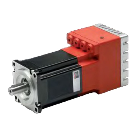
Motor Power Company DUET AD Series User manual

Version 1.1
20/01/2022
Profinet Reference
Manual
DUET AD

Profinet Reference Manual - Pag. 1

Profinet Reference Manual - Pag. 2
1. Sommario
2. General .........................................................................................................5
Introduction......................................................................................................... 5
Notice:................................................................................................................5
PROFINET Compatibility ......................................................................................... 5
Document Versioning ............................................................................................ 5
Profinet documentation.......................................................................................... 5
3. Wiring and pin assignment................................................................................ 7
Connection .......................................................................................................... 7
Pin assignment..................................................................................................... 7
Bus cable ............................................................................................................8
4. PROFINET connection....................................................................................... 9
Introduction......................................................................................................... 9
Slave overview..................................................................................................... 9
Master overview ................................................................................................. 10
Add the GSDML file................................................................................................ 10
Add servo drive to PROFINET network....................................................................... 11
Specify the device name......................................................................................... 12
5. I/O Cyclic Data ............................................................................................. 14
Controller data input in profile position mode (Mode of operation 1):........................... 15
Controller data output in profile position mode (Mode of operation 1):......................... 15
Controller data input in profile velocity mode (Mode of operation 3):........................... 16
Controller data output in profile velocity mode (Mode of operation 1):......................... 16
Controller data input in current mode (Mode of operation 4):..................................... 16
Controller data output in current mode (Mode of operation 4):................................... 17
6. Device Control .............................................................................................. 18
Device Control and State Machine ......................................................................... 18
Indicating the Operating State................................................................................. 19
Starting and Changing an Operating Mode................................................................. 22

Profinet Reference Manual - Pag. 3
Profile Position Mode ........................................................................................... 23
Functional Description ............................................................................................ 23
Example: Profile Position ........................................................................................ 25
Homing Mode..................................................................................................... 27
Homing methods ................................................................................................... 29
Example: Homing .................................................................................................. 35
Profile Velocity Mode ........................................................................................... 36
Example: Profile Velocity ........................................................................................ 37
Profile Torque Mode ............................................................................................ 38
7. Units ........................................................................................................... 41
Encoder resolution .............................................................................................. 41
Conversion factor for position units........................................................................ 41
Conversion factor for the speed units ..................................................................... 42
Example: ............................................................................................................. 42
Conversion factor for the acceleration units............................................................. 43
8. Manufacturer Specific Parameters Objects ......................................................... 43
How to read/write parameters records ................................................................... 43
FUNCTION BLOCK FOR R/W PARAMETERS ................................................................. 44
FB WRREC............................................................................................................ 44
FB RDREC ............................................................................................................ 45
Device parameters list ......................................................................................... 46
PNU .................................................................................................................... 46
Name .................................................................................................................. 46
Type.................................................................................................................... 46
Size .................................................................................................................... 46
(byte).................................................................................................................. 46
Description........................................................................................................... 46
R/W .................................................................................................................... 46
Unit..................................................................................................................... 46

Profinet Reference Manual - Pag. 4
Range.................................................................................................................. 46
PNU 669: Fault Register ......................................................................................... 53
PNU 663: Digital Inputs .......................................................................................... 54
PNU 664: Digital Outputs ........................................................................................ 55
9. PROFINET function blocks and data blocks for SIEMENS S7 .................................. 56
Overview........................................................................................................... 56
Hardware configuration........................................................................................ 56
Integration of the servo drive ............................................................................... 57
Function blocks for DUET AD ................................................................................ 58
I/O data association in Tia Portal v15.1 ..................................................................... 58
FB for velocity mode .............................................................................................. 61
FB for profile position mode .................................................................................... 62
FB for homing mode .............................................................................................. 64
Example project: Moving the Axis in Velocity Profile Mode ............................................ 66

Profinet Reference Manual - Pag. 5
2. General
Introduction
This manual describes, in detail, the PROFINET implementation of Motor Power Company DUET AD.
Notice:
This guide is delivered subject to the following conditions and restrictions: This guide contains
proprietary information belonging to Motor Power Company srl. Such information is supplied solely
for the purpose of assisting users of the Motor Power Company devices and servo drive in its
installation and configuration.
•The text and graphics included in this manual are for the purpose of illustration and
reference only. The specifications on which they are based are subject to change without
notice.
•Motor power Company and the Motor power Company logo are trademarks of Motor
Power Company srl.
•Information in this document is subject to change without notice.
PROFINET Compatibility
This document is compatible with the following FW and EDS version and superior:
GSDML Version
FW version
Note
1.2.x
1.2.X
-
Document Versioning
Version
Date
Author
Note
1.0
20/01/2023
Michele Piacentini
Lorenzo Bedogni
Anouar Irhlam
First Release
Profinet documentation
PROFINET (PROcess FIeld NETwork) is a standard developed by the German association PROFIBUS
Nutzerorganisation e.V. A complete description of the fieldbus systems can be found in the
following standards:
IEC 61158 "Digital data communication for measurement and control –Fieldbus for use in industrial
control systems": This standard has several parts and defines the "Fieldbus Protocol Types". In
accordance with these types, PROFINET is specified as type 10.

Profinet Reference Manual - Pag. 6
IEC 61784-2 "Industrial communication networks - Profiles - Part 2: Additional fieldbus profiles for
real-time networks based on ISO/IEC 8802-3 (IEC 61784-2:2014)": This standard defines the real-time
classes (RTC = real-time class) based on the reaction time.
DUET AD only support PROFINET RT conformance Class A/B.
Further information, contact addresses etc. can be found under www.profibus.com.

Profinet Reference Manual - Pag. 7
3. Wiring and pin assignment
Connection
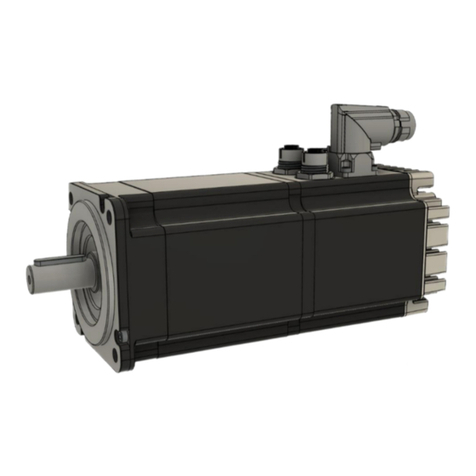
For the DUET AD series, the PROFINET interface has been realized with two M12 female jacks.
FIGURE 1DUETAD PROFINET CONNECTION
Follow the Installation Guide (available at www.motorpowerco.com in dedicated section) of the
device to find out the entire pinout configuration.
Usually, a series connection could be implemented as in figure below:
FIGURE 2TYPICAL PROFINET MULTIPLE NODE CONFIGURATION
Both connectors can act as input or output.
Pin assignment
FIGURE 3PIN ASSIGNMENT OF PROFINET INTERFACE

Profinet Reference Manual - Pag. 8
Bus cable
A PROFINET copper cable is usually a 4-core, shielded copper cable. Like in the case of standard
Ethernet applications, the maximum distance that can be covered by way of copper cables is
limited to 100 m between the communication endpoints. The link is defined as a PROFINET end-to-
end link.
The only cables that can be used in automation systems are PROFINET
cables. PROFINET cables have a corresponding manufacturer's declaration.
The joint use of power cables and copper cables for communication
purposes is subject to regulations to minimize the electromagnetic influence
of the power cables on the communication cables. When setting up the
PROFINET network, it is essential to follow the advice that is given in the
technical literature and to comply with the information and notes
hereinafter in order to realise a stable, trouble-free system.

Profinet Reference Manual - Pag. 9
4. PROFINET connection
Introduction
PROFINET IO (Input - Output) enables the connection of decentralised field devices, such as I/Os,
drives, valves, transducers, or analysis devices, to a central automation device, such as a PLC, PC,
or process control system. Data transfer is based on the Fast Ethernet standard transmission with 100
Mbit/s. PROFINET IO follows the provider-consumer model for the data exchange. This is the only
supported protocol in DuetAD series (no PROFIdrive or PROFIBUS standard are supported).
The set-up of a fully functional PROFINET connection requires several steps. Some of these settings
should or must be performed prior to the activation or start of the bus communication. This chapter
provides an overview of the required steps. The exact procedure is described in the following
chapters.
Slave overview
This section provides an overview of the necessary steps for the parameterisation and
configuration of the slave. Since some of the parameters will not become effective until after they
have been stored and a reset has been performed, we recommend the following workflow:
•Configuration of the telegrams with the the setting of proper mode of operation, chapter 5
•Selection and parameterisation of the physical units, chapter 7
•Configuration and activation of the operating parameters, chapter 8
The total length of the IO exchanged is fixed at 16 bytes, even though the mapping can be
changed by selecting the proper mode of operation for the device.
For a complete configuration of the device a specific parametrization via records may be
necessary-
Important process data concerning the position, speed, and acceleration are handed over in
physical units. These should be parameterised prior to starting the communication, since they
define the interpretation of the data in the servo drive.

Profinet Reference Manual - Pag. 10
Master overview
This section provides an overview of the necessary steps for the parameterisation and
configuration of the master. The following procedure is recommended:
•Add the GSDML file
•Add servo drive to PROFINET network
•Specify the device name
On the master side, the servo drive must be integrated into the PROFINET network. The following
section describes this, based on an example using integration under SIEMENS SIMATIC S7. For a
complete example refer to chapter 9.
Add the GSDML file
If the servo drive is not included in the device or hardware catalogue, the GSDML file must be
installed first. The GSDML file can be found in the software folder in the specific download area at
www.motorpowerco.com. To install it go to “Options>Manage general station description files”.
FIGURE 4-MANAGE GENERAL STATION DESCRIPTION FILES
NOTE: GSDML file is available at
www.motorpowerco.com

Profinet Reference Manual - Pag. 11
Add servo drive to PROFINET network
To integrate the servo drive into the PROFINET network, the servo drive must be selected in the
hardware catalog. The DuetAD device can be found in “Other field devices > PROFINET IO > I/O >
Hilscher Gesellschaft fur Systemautomation mbH > PNS“
FIGURE 5PROFINET DEVICE SELECTION IN HARDWARE CATALOG
The DuetAD head module must be dragged and dropped into the topology view of the device
configuration. After the selection of the network view, the servo drive must be assigned to an I/O
controller via the link "Not assigned".
FIGURE 6ADDING GSDML FILE IN TIA PORTAL

Profinet Reference Manual - Pag. 12
Specify the device name
Then, the device name must be specified. This method has been chosen for PROFINET, since
names are easier to handle than complex IP addresses. After clicking the netX logo of the servo
drive, the device name can be changed under "General" in the "Properties" window. The name of
the configured device must later be assigned to the physical device.
User has several ways to do that. Here are described two of them:
1. Directly from SIEMENS TIA Portal
2. SIEMENS PRONETA tool
SIEMENS PRONETA tool
The PROFINET network analyzer PRONETA Basic is a simple tool intended for the rapid analysis and
configuration of PROFINET networks and the simple testing of ET 200 distributed IO systems and
other components.
FIGURE 7-PRONETA TOOL OVERVIEW

Profinet Reference Manual - Pag. 13
PRONETA Basic is well suited for solving two tasks fundamental to the commissioning of PROFINET
installations:
•The “Network Analysis" task gives a quick overview of the devices connected to PROFINET. It
features simple configuration options, like setting network parameters or assigning a network
name to the devices which are part of the subnet the PRONETA PC is connected. The
application also provides powerful mechanisms to compare several network topologies with
each other, for example to compare an “ideal” topology intended for a project with the
actual installation.
•The “IO Test" task is a simple and intuitive method to test the IO wiring of an installation with
numerous distributed IO devices. It allows for checks of the wiring and will automatically set
up a protocol of the test procedure which can be exported for documentation purposes.
Both tasks can be performed before a CPU is integrated in the network. Since there are no other
engineering tools required, PRONETA Basic allows fast and convenient checks of the system
configuration from early on.
FIGURE 8-DEVICE NAME AND IP CONFIGURATION FOR THE STATION WITH PRONETA

Profinet Reference Manual - Pag. 14
5. I/O Cyclic Data
Cyclic I/O data are transmitted via the "IO Data CR" unacknowledged as real-time data between
provider and consumer in an assignable time base.
The cycle time can be specified individually for connections to the individual devices and are thus
adapted to the requirements of the application.
Likewise, different cycle times can be selected for the input and output data, within the range of
from 250 µs to 512 ms.
The connection is monitored using a time monitoring setting that is derived from a multiple of the
cycle time. During data transmission in the frame, the data of a subslot are followed by a provider
status.
This status information is evaluated by the respective consumer of the I/O data. It can use this
information to evaluate the validity of the data from the cyclic data exchange alone. In addition,
the consumer statuses for the counter direction are transmitted.
The connection is monitored using a time monitoring setting that is derived from a multiple of the
cycle time. During data transmission in the frame, the data of a subslot are followed by a provider
status. This status information is evaluated by the respective consumer of the I/O data. It can use
this information to evaluate the validity of the data from the cyclic data exchange alone. In
addition, the consumer statuses for the counter direction are transmitted
Only one standard and defined Telegram is supported in the DUET AD exchanges 32 bytes on the
fieldbus; 16 bytes are set as controller inputs and 16 bytes are set as controller output
As stated I/O data are fixed in size but their data are flexible to support all mode of operation
described in previous chapter.
Changing mode of operation also change the content variables for data input and output.
FIGURE 9- TELEGRAM MODEL

Profinet Reference Manual - Pag. 15
In next chapter will be described the mapping for any mode of operation supported by DUETAD..
NOTE: Changing mode of operation also change the content variables for
data input and output, this is done automatically by drive
Controller data input in profile position mode (Mode of operation 1):
NOTE: Current limitation is not active if set to 0 in controller data output!
Byte
Parameter
Designation
Type
Comments
0-1
Statusword
Drive’s statusword
UNIT16
2
Mode of
Operation
Display
Drive’s mode of
operation
INT8
This value must be 1 for proper
operation
3-6
Position
actual
value
Actual position
INT32
7
Spare
Spare byte
BYTE
NOT USED
8-9
Actual
motor
current
Motor current
consumption
INT 16
Actual motor current expressed in
per thousand of motor nominal
current
10-
15
Spare
Spare bytes
BYTES
NOT USED
Controller data output in profile position mode (Mode of operation 1):
Byte
Parameter
Designation
Type
Comments
0-1
Controlword
Drive’s controlword
UNIT16
2
Mode of
Operation
Drive’s mode of
operation
INT8
This value must be 1 to set drive in
profile position mode
3
Homing
Method
Drive’s homing
method
INT8
Homing methods only takes effect
in homing mode
4-7
Position
Target
Drive’s target
position
INT32
8-9
Current
limitation
Motor current
limitation
INT 16
Motor current limitation expressed
in per thousand of motor nominal

Profinet Reference Manual - Pag. 16
current. When 0 this function is
disabled.
10-
15
Spare
Spare bytes
BYTES
NOT USED
Controller data input in profile velocity mode (Mode of operation 3):
Byte
Parameter
Designation
Type
Comments
0-1
Statusword
Drive’s statusword
UNIT16
2
Mode of
Operation
Display
Drive’s mode of
operation
INT8
This value must be 3 for proper
operation
3-6
Velocity
actual
value
Actual position
INT32
7
Spare
Spare byte
BYTE
NOT USED
8-9
Actual
motor
current
Motor current
consumption
INT 16
Actual motor current expressed in
per thousand of motor nominal
current
10-
15
Spare
Spare bytes
BYTES
NOT USED
Controller data output in profile velocity mode (Mode of operation 1):
Byte
Parameter
Designation
Type
Comments
0-1
Controlword
Drive’s controlword
UNIT16
2
Mode of
Operation
Drive’s mode of
operation
INT8
This value must be 3 to set drive in
profile position mode
3
Homing
Method
Drive’s homing
method
INT8
Homing methods only takes effect
in homing mode
4-7
Target
velocity
Drive’s target
position
INT32
8-9
Current
limitation
Motor current
limitation
INT 16
Motor current limitation expressed
in per thousand of motor nominal
current. When 0 this function is
disabled.
10-
15
Spare
Spare bytes
BYTES
NOT USED
Controller data input in current mode (Mode of operation 4):
Byte
Parameter
Designation
Type
Comments
0-1
Statusword
Drive’s statusword
UNIT16

Profinet Reference Manual - Pag. 17
2
Mode of
Operation
Display
Drive’s mode of
operation
INT8
This value must be 4 for proper
operation
3-4
Actual
Current
Actual position
Int16
5-6
Spare
Spare byte
BYTES
NOT USED
7
Spare
Spare byte
BYTE
NOT USED
8-9
Actual
motor
current
Motor current
consumption
INT 16
Actual motor current expressed in
per thousand of motor nominal
current
10-
15
Spare
Spare bytes
BYTES
NOT USED
Controller data output in current mode (Mode of operation 4):
Byte
Parameter
Designation
Type
Comments
0-1
Controlword
Drive’s controlword
UNIT16
2
Mode of
Operation
Drive’s mode of
operation
INT8
This value must be 4 to set drive in
profile position mode
3
Homing
Method
Drive’s homing
method
INT8
Homing methods only takes effect
in homing mode
4-5
Target
Current
Drive’s target
position
INT16
6-7
Spare
Spare bytes
BYTES
NOT USED
8-9
Current
limitation
Motor current
limitation
INT16
Motor current limitation expressed
in per thousand of motor nominal
current. When 0 this function is
disabled.
10-
15
Spare
Spare bytes
BYTES
NOT USED

Profinet Reference Manual - Pag. 18
6. Device Control
FIGURE 10-COMMUNICATION MODEL FOR DUETAD PN
Device Control and State Machine
The power drive system finite-state automaton (PDS FSA) is a mathematical model that defines the
behavior of the power drive system. Because a power drive system is required to provide local
control even when the communication network is not functioning properly, the communication
FSA and the PDS FSA are only loosely coupled. Figure shows how the power drive system operates
remotely via the network, or locally.
Transmission system
Ethernet
Communication protocol
PROFINET
i
User layer
PROFINET layers
FIGURA 1-REMOTE AND LOCAL CONTROL
Application protocol CiA
DS402 CANopen

Profinet Reference Manual - Pag. 19
The power drive system is operated by the Controlword sent by the control device via the network.
The state of the power drive system is reported by the Statusword produced by the drive device.
The FSA is also controlled by error detection signals.
The PDS FSA defines the power drive system status and the possible control sequence of the power
drive system. A single state represents a special internal or external behavior. The state of the
power drive system also determines which commands are accepted. For example, it is only
possible to start a point-to-point move when the drive is in the operation enabled state.
Indicating the Operating State
After switching on, and when an operating mode is started, the power drive system goes through a
number of operating states. The operating states are internally monitored and influenced by
monitoring functions
Figure illustrates the PDS FSA behavior. It takes into consideration the control of the power
electronics, in accordance with user commands and internal drive faults.
FIGURA 2-POWER DRIVE SYSTEM STATE DIAGRAM
Table of contents
Other Motor Power Company Servo Drive manuals

Motor Power Company
Motor Power Company DMR 50-5/50 V3.0 User manual

Motor Power Company
Motor Power Company FLEXI PRO Series User manual

Motor Power Company
Motor Power Company DUET_FL 48/10 User manual

Motor Power Company
Motor Power Company DMR 50-5 User manual

Motor Power Company
Motor Power Company Duet AD 80 User manual
Popular Servo Drive manuals by other brands

Savch
Savch SDA2 Series user manual

Danfoss
Danfoss AMV 655 installation guide

Baumuller
Baumuller b maXX 5000 Instruction handbook

Allen-Bradley
Allen-Bradley Ultra3000 installation manual

Rockwell Automation
Rockwell Automation Allen-Bradley Kinetix 5700 Series user manual

ABB
ABB 8 Series Use and installation manual