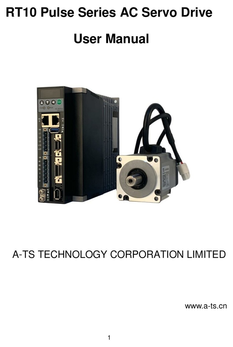
A-TS TECHNOLOGY RT20 User manual

1
RT20 Pulse Series AC Servo Drive
User Manual
A-TS TECHNOLOGY CORPORATION LIMITED
www.a-ts.cn

www.a-ts.cn A-TS Technology RT20
2
DECLARATION
Without written permission, reprint or copy is strictly forbidden.
Unauthorized copying, dissemination or use of this document and its
contents is prohibited. Violators will be liable for compensation.
All rights, including the rights granted by patent rights and the registration
rights of application models or designs will be reserved.
The information provided in this publication will be updated regularly, and
any necessary corrections will be implemented in subsequent releases.
Suggestions for improvement are welcome at any time.
Version
Product
Release Date
Note
V-23-01
RT20
24.03.2023
N/A

www.a-ts.cn A-TS Technology RT20
3
Forward
The RT20 series ac servo is provided by A-TS Technology Co., Ltd. in
China.
To have a thorough understanding, please read this manual carefully and
follow all safety precautions before moving, installing, operating and
maintaining the servo.
This manual provides guidance on safety precautions, product
specifications, installation and wiring, keyboard operation, parameter
settings, alarms, trouble-shooting, routine maintenance etc. It doesn’t
include all the security matters or considerations.
Local laws and regulations
All the local laws, regulations, and codes of practice should be obeyed first,
besides the instructions in the manual.
Disclaimer of Liability
We have reviewed the contents of this publication to ensure consistency
with the hardware and software described.
Since variance cannot be precluded entirely, we cannot guarantee full
consistency. However, the information in this publication is reviewed
regularly and any necessary corrections are included in subsequent
editions.
Thank you for choosing A-TS.
A-TS, automation technologies, at your services.

www.a-ts.cn A-TS Technology RT20
4
In this document, the following symbols may appear. The meaning they
represent is as follows.
Symbol
Instructions
DANGER
Attention, please! If there is improper operation, it may
cause serious consequences such as personal safety,
equipment safety or environmental safety.
WARNING
Be careful! If there is improper operation, it may cause
major accident, such as equipment damage or physical
injury.
ATTENTION
If there is misoperation, it may cause bad effects or cannot
be operated normally. Generally speaking, the issues
caused could be solved.
INSTRUCTIONS
It is widely used. It reminds the instructions and prompts.
EXAMPLE
For the better understanding of the users, to show a brief
example.
NOTE
It offers small functions and tips unnoticeable that are very
convenient to use.

www.a-ts.cn A-TS Technology RT20
5
Contents
Forward....................................................................................................................3
Contents ..................................................................................................................5
1 Safety Precautions................................................................................................7
1.1 General precautions......................................................................................7
2 Product Information...............................................................................................9
2.1 Product introduction.......................................................................................9
2.2 Order number................................................................................................9
2.3 Technical specifications...............................................................................10
3 Installation and Wiring.........................................................................................13
3.1 Installation...................................................................................................13
3.1.1 Installation environment .......................................................................13
3.1.2 Products appearance and dimensions.................................................14
3.1.3 Installation direction .............................................................................15
3.1.4 Installation space .................................................................................15
3.2 Wiring and terminals....................................................................................17
3.2.1 Wiring diagram.....................................................................................17
3.2.2 Strong power terminals ........................................................................18
3.2.3 Command terminal CN3.......................................................................21
3.2.4 Encoder terminal CN4/CN5 definition ..................................................25
3.2.5 USB debugging port CN1 definition .....................................................29
3.2.6 RS485 communication port CN2A/CN2B definition..............................30
3.2.7 Wiring of three control mode................................................................31
4 Display and Keyboard Operation........................................................................34
4.1 Basic operation............................................................................................34
4.2 Menu level one............................................................................................35
4.3 Menu level two.............................................................................................36
4.3.1 Monitoring ............................................................................................36
4.3.2 Parameter setting (Pa/Fn parameter)...................................................38
4.3.3 Parameter management.......................................................................39
4.3.4 Speed test run......................................................................................41

www.a-ts.cn A-TS Technology RT20
6
4.3.5 JOG running.........................................................................................41
5 Commissioning and Running..............................................................................43
5.1 Wiring and inspection..................................................................................43
5.2 Set motor type.............................................................................................44
5.3 Speed trial running ......................................................................................46
5.4 JOG trial running .........................................................................................47
5.5 Position control............................................................................................49
5.5.1 Position control simple example...........................................................49
5.5.2 Position command................................................................................50
5.5.3 Electronic gear setting..........................................................................52
5.6 Speed and torque control............................................................................53
5.7 RS485 control setting..................................................................................54
6 Adjustment..........................................................................................................58
6.1 Summary.....................................................................................................58
6.2 Inertia identification......................................................................................58
6.3 Automatic gain adjustment..........................................................................60
6.4 Manual gain adjustment ..............................................................................61
6.5 Resonance suppression..............................................................................61
7 Parameters.........................................................................................................63
7.1 Parameter list ..............................................................................................63
7.1.1 PA parameters.....................................................................................63
7.1.2 Fn parameters......................................................................................70
7.1.3 Bn parameters......................................................................................73
8 Fault Alarm .........................................................................................................74
8.1 Alarm code list.............................................................................................74
The End...............................................................................................................77

www.a-ts.cn A-TS Technology RT20
7
1 Safety Precautions
1.1 General precautions
This manual provides guidance on safety precautions, product
specifications, installation and wiring, keyboard operation, parameter
settings, alarms, trouble-shooting, routine maintenance etc. It doesn’t
include all the security matters or considerations.
When installing, operating, and maintaining the RT20 series ac servo,
please follow all the safety instructions in this manual, especially where
there is safety symbols. All the safety symbols are the tips to the safety
precautions. It doesn’t include all the security matters or considerations.
For any injury or loss caused by improper operation, the A-TS
technology will not take the responsibility. The A-TS technology is not
legally bound in any manner either.
Basic installation requirement
Only qualified or strictly trained engineers are allowed to install,
operate and maintain equipment.
Only qualified professionals are allowed to dismantle devices and
repair equipment.
Replacing or changing hardware & software must be carried out by the
authorized engineers.
The operator shall report the failure or error to the person in charge in
time promptly.
Grounding requirement
The following requirements are for devices that need to be grounded
only.

www.a-ts.cn A-TS Technology RT20
8
Before installing the equipment, grounding first. When removing the
equipment, keep the grounding until the end.
It is forbidden to damage the grounding conductor.
It is forbidden to operate equipment without the grounding conductor.
The equipment shall be grounded always. Before operating, make
sure the electrical connection is fine and reliable.
Equipment safety
Before operation, the equipment should be fixed in the electric cabinet
or on other stable objects firmly, such as the table or floor.
When the system is running, make sure the air vent is unobstructed.
When installing the equipment, to tighten the screws, use the tool.
After complete the installation, please take all the empty packing
materials area away.

www.a-ts.cn A-TS Technology RT20
9
2 Product Information
2.1 Product introduction
RT20 series servo is all digital ac servo drive, with high reliability,
performance and cost effectiveness.
High voltage servo, working at three phases 380V AC, with high
voltage motor.
Supports position control, speed control and torque control mode.
Supports incremental encoder, ABZ incremental encoder, absolute
encoder including Tamagawa, BISS, and Nikon, and
Magnetoelectricity encoder (ME).
Supports RS485 communication, standard Modbus protocol.
Supports internal speed mode and demonstration running mode.
2.2 Order number
Code Series Code Voltage level
HHigh voltage, three-
phase 380V
Code Increm
ental
E00
E01
E02
E03
ABZ
increm
ental BISS Tamag
awa ME
Absolute encoder type
●●×× ×
●××
●
●●×●
×
×
●
●×
RT20 –PA 050 H –E02 –
Series Power level Encoder typeVoltage
RT20 series ac
servo drive OEM code
Peak current
6.7A
16.8A
23.5A
33.6A
Code
010
025
035
050
10.1A015
PA Pulse higher type
●●
Nikon
×
×
●
×
075 50.4A
Figure 2-1 RT20 series AC servo drive order number

www.a-ts.cn A-TS Technology RT20
10
INSTRUCTIONS
●Support this feature.
× Don’t support this feature.
2.3 Technical specifications
Table 2-1 RT20 series pulse series technical specification
Model
RT20 series AC servo drive
RT20-PA□□□H-E02
010
015
025
035
050
075
Power supply
Three-phase AC380V (-15%)-440V(+10%), 50/60Hz
Rated current (rmsA)
3.5
5.0
7.5
12.0
15.5
22.5
Maximum current (rmsA)
6.7
10.1
16.8
23.5
33.6
50.4
Peak current (o-pA)
9.5
14.3
23.8
33.3
47.5
71.3
Environm
ent
Temperature
Working 0-55°C (If the ambient temperature is
between 45°C and 55°C, the average load should not
exceed 80% of the rated load.)
Storage -20°C -65°C
Humidity
Working 40%-80% (No condensation)
Storage Less than 93% ( No condensation)
Protection grade
IP20
Control method
PWM sine wave vector control
Regenerative braking
Optional, built-in or external
Feedback
ABZ incremental encoder, standard incremental
encoder, and absolute encoder
Control mode
Position/Speed/Torque
Control input
Up to 8 input terminals (optoelectronic isolation).
Servo-enable, alarm clearance, CWL, CCWL,

www.a-ts.cn A-TS Technology RT20
11
forward torque limitation, reverse torque limitation,
zero speed clamp, internal speed selection 1,
internal speed selection 2, mode switch 1, mode
switch 2, forward jog, backward jog, torque command
direction setting, speed command direction setting,
electronic gear selection 1, electronic gear selection
2, position deviation clearance, pulse input
prohibition, origin return (homing) trigger, origin
return (homing) reference point
Control output
Up to 5 output terminals (optoelectronic isolation).
Servo ready (S-RDY), alarm, zero speed, positioning
complete, speed reached, torque reached,
electromagnetic brake, servo in operation, location
nearby, positioning, torque in limitation, speed in
limitation, origin return (homing) complete
Encoder
signal
output
Signal type
A, B, Z differential output, Z signal open collector
output
Frequency
dividing ratio
It can be configured with parameter PA78
Position
Command
source
Internal position command, pulse command
Input frequency
Pulse command port, differential input≤4Mpps
single-ended input≤500kpps
Command mode
Direction + pulse sequence. CW+CCW pulse
sequence.
Two phase A/B orthogonal pulse
Internal position command
Electronic gear
ratio
Numerator, 1-32767
Denominator, 1-32767
Speed
Command
Parameter setting

www.a-ts.cn A-TS Technology RT20
12
ACC/DEC
Analog command
input
Support -10V - +10V input
Command source
Internal speed command, analog command
Torque
Speed limitation
Parameter setting
Analog command
input
Support -10V - +10V input
Command
source
Internal torque command, analog command
Special function
Origin return(homing), gain switch, mechanical
resonance notch filter
Monitoring function
Rotation speed, current position, position deviation,
motor torque, motor current, command pulse
frequency, etc.
Protection function
Over speed, over voltage, over current, over load,
braking abnormal, encoder abnormal, position out of
tolerance, etc.
Features
Speed
frequency
response
≥1500Hz
Speed
fluctuation ratio
≤±0.03% (Load 0-100%)
≤±0.02% (Power -15%-+10%)
Speed ratio
1:10000

www.a-ts.cn A-TS Technology RT20
13
3 Installation and Wiring
3.1 Installation
When installing, operating and maintaining the RT series ac servo drive,
please follow the instructions in the manual.
3.1.1 Installation environment
Working temperature 0-55°C
Working humidity below 80% RH (no condensation)
Storage temperature -20°C-65°C
Storage humidity below 80% RH (no condensation)
Vibration below 4.9 m/s2
Altitude below 2000m
Install in a well-ventilated place with little humidity and dust
Install in the place without corrosive gas, flammable gas, pyrophoric
gas, oil gas, cutting fluid, cutting powder, or iron powder etc.
WARNING
When in a vibration environment, to prevent transmitting vibration to the
servo drive, please install the anti-rattle device on the mounting surface
of the servo drive.
When it has to be used in a corrosive gas environment, please try to keep
corrosive gas out of the devices. The corrosive gas will cause the aging
of electronic components and circuit boards.

www.a-ts.cn A-TS Technology RT20
14
3.1.2 Products appearance and dimensions
64 75 183
155,5
166
Figure 3-1 RT20-PA010/015H Appearance and dimensions (Unit, mm)
155,5
84 95 183
166
Figure 3-2 RT20-PA025/035HAppearance and dimensions (Unit, mm)
104 115 210
260
249,5
Figure 3-3 RT20-PA050/075H Appearance and dimensions (Unit, mm)

www.a-ts.cn A-TS Technology RT20
15
3.1.3 Installation direction
Install the servo drive as the figure below. Good ventilation and heat
dissipation must be ensured.
Base
Airflow
Airflow
Figure 3-4 RT20 seriesAC servo drive installation direction (Unit, mm)
INSTRUCTIONS
The drive should be mounted vertically on the base.
Use natural convection or fan to cool the drive.
Use M4 screws for the installation.
3.1.4 Installation space
Reserve enough space as shown in Figure 3-5. Make sure that the air
flows from bottom to top, good for heat dissipation.

www.a-ts.cn A-TS Technology RT20
16
Ventilate
>100 mm>100 mm
>40mm
>10mm >10mm >10mm>40mm
Figure 3-5 RT20 seriesAC servo drive installation space
The working temperature should be below 45℃, to make sure the
reliable performance.
If the working temperature keeps above 45℃, please place the drive in
the place with good ventilation. If it is installed in an electric cabinet,
make sure that the size and ventilation is good enough inside the
cabinet to avoid overheating.
Make sure to ground the terminals, otherwise it may cause electric
shock or interference that may cause danger due to misoperation.
When wiring the drive, please route the cable downwards to prevent
liquid from flowing into the drive when it is attached to the cable.

www.a-ts.cn A-TS Technology RT20
17
3.2 Wiring and terminals
3.2.1 Wiring diagram
CNC system, PLC or
other upper machine
Debugging
Cable
Command
Cable
Motor Power Cable Encoder
Cable
Air Circuit Breaker
To protect the power circuit,
make sure to use a proper air
circuit breaker as the protection
device.
Noise Filter
Prevent external Interference,
and reduce the interference by
servo for other devices.
Magnetic Contactor
Turn the power supply on or off. It
works with the coil surge
absorbers.
·Strictly prohibit to use the
magnetic contactor to operate or
stop the motor !
Power
cable
Power Supply
three phase,AC380V
Resistor
The braking resistor is optional.
By default, the B2 and B3 are shorted,
the internal resistor is used. When the
internal resistor is not big enough,
disconnect the B2 and B3, and connect
external resistor between the B1 and B2.
RS485 interface
IN/OUT
CN3
CN2A
CN1
RT20 AC Servo System
A-TS Technology
CN4
CN2B
Figure 3-6 RT20-PA pulse series AC servo drive wiring diagram
DANGER
Wiring operation should be performed by professional technicians.
In order to avoid electric shock, after turn off the power, wait for more

www.a-ts.cn A-TS Technology RT20
18
than 5 minutes, and then disassemble the drive.
Please connect the servo drive and servo motor after completing the
installation, otherwise it may cause electric shock.
Do not damage the cable, apply excessive pressure to it, hang heavy
objects or squeeze, etc., otherwise it may cause electric shock.
To avoid electric shock, please insulate the power terminal wiring.
The specifications and installation methods of external wiring must be
complied with all the local regulations.
Make sure to ground the entire system.
ATTENTION
Please wire correctly and carefully, otherwise it will cause abnormal operation
of the servo motor and may cause injury.
Do not make mistakes in the connection terminals, otherwise it may cause
cracks and damage.
INSTRUCTIONS
RT-STP is the Servo Tuning Program. It’s a debugging software provided by
the A-TS Technology. For more details, please contact with us at www.a-ts.cn.
3.2.2 Strong power terminals
1. RT20-PA010/15/25/35 strong electricity terminals.

www.a-ts.cn A-TS Technology RT20
19
Table 3-1 RT20 series drive strong power terminals
Terminal
Labels
Name
Specifications
L1C
Control power
input terminals
Connect to single-phase 380V AC power
380V (-15%)-440V (+10%)
L2C
L1
Main power
supply input
terminals
Connect to three-phase 380V AC power
380V (-15%)-440V (+10%)
L2
L3
B1/P(+)
Braking resistor
terminals,
common DC
bus terminal
When using internal braking resistor, short
circuit B2 and B3.
When using external braking resistor,
disconnect B2 and B3, and connect the
braking resistor between P and B2.
When using a common DC bus, P/N
terminals are connected to positive/negative
voltage respectively.
B2
B3
N(-)
U
Motor power
terminals
It must be connected with the U, V, W, PE
terminals of the motor correspondingly.
(Note, the PE is the terminal on the metal
V
W

www.a-ts.cn A-TS Technology RT20
20
PE
heat sink of the drive)
WARNING
L1/L2/L3 cannot be connected to single-phase 380V, but must be connected
to three-phase 380V. Short-circuit L1C and L1, L2C and L2.
2. RT20-PA050/75 strong electricity terminals.
Table 3-2 RT20-EA050/75 servo drive strong power terminals
Terminal
labels
Name
Specifications
L1C
Control power
input terminals
Connect to single-phase 380V AC power
380V (-15%)-440V (+10%)
L2C
L1
Main power
supply input
terminals
Connect to three-phase 380V AC power
380V (-15%)-440V (+10%)
L2
L3
B1/P(+)
Braking resistor
When using internal braking resistor, short
Table of contents
Other A-TS TECHNOLOGY Servo Drive manuals
Popular Servo Drive manuals by other brands
Sanyo Denki
Sanyo Denki SANMOTION R3E manual
AXOR Industries
AXOR Industries MiniMagnum Series Service manual
AB Quality
AB Quality ALLEN-BRADLEY 1391-DES user manual

Mitsubishi Electric
Mitsubishi Electric MELSERVO MR-HP30KA instruction manual
Wittenstein
Wittenstein TPM+ power quick start guide
YASKAWA
YASKAWA SERVOPACK Sigma 7S Series Supplementary manual
