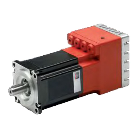
Motor Power Company Duet AD 80 User manual

Version 1.1
14/10/2022
EtherCAT –CANopen
Reference Manual
For Duet AD 80

CANOpen Implementation Guide Manual Pag. 1

CANOpen Implementation Guide Manual Pag. 2
1.Index
1. Index ............................................................................................................2
CANopen Compatibility ..........................................................................................8
EtherCAT Compatibility ..........................................................................................8
Document Versioning ............................................................................................8
2. Introduction ...................................................................................................9
Scope ....................................................................................................................9
CANopen................................................................................................................9
EtherCAT ............................................................................................................. 10
Cabling and pin assignment CANopen ....................................................................... 10
Cabling and pin assignment EtherCAT ....................................................................... 11
Cabling Hints CANopen........................................................................................... 12
Node address in CANopen network ........................................................................... 13
Node address in CANopen network ........................................................................... 14
Bit Rate in CAN Network ......................................................................................... 14
3. CANopen Operation ....................................................................................... 15
Device communication ........................................................................................... 15
Communication Objects.......................................................................................... 16
Service Data Communication ................................................................................ 17
Process Data Communication................................................................................ 17
Device Control and State Machine ......................................................................... 20
Indicating the Operating State .............................................................................. 20
Changing the operating state................................................................................ 23
Starting and Changing an Operating Mode .............................................................. 24
Profile Position Mode .............................................................................................. 25
Functional Description ......................................................................................... 25
Homing Mode........................................................................................................ 29
Functional description ............................................................................................ 31
Homing methods ................................................................................................... 32

CANOpen Implementation Guide Manual Pag. 3
Method 1: Homing on the negative limit switch and index pulse ................................. 32
Method 2: Homing on the positive limit switch and index pulse .................................. 33
Methods 3 and 4: Homing on the positive home switch and index pulse....................... 33
Methods 5 and 6: Homing on the negative home switch and index pulse...................... 34
Methods 7 to 14: Homing on the home switch and index pulse................................... 35
Methods 17 to 30: Homing without an index pulse ................................................... 37
Methods 33 to 34: Homing on the index pulse ......................................................... 37
Method 35: Homing on the current position ............................................................ 38
Profile Velocity Mode .............................................................................................. 39
Profile Torque Mode ............................................................................................... 42
Interpolated Position Mode...................................................................................... 44
Cyclic Synchronous Position Mode ............................................................................ 48
4. Units ........................................................................................................... 51
Encoder resolution................................................................................................. 52
Conversion factor for position units .......................................................................... 52
Conversion factor for the speed units........................................................................ 53
Conversion factor for the acceleration units ............................................................... 53
5. Communication Profile ................................................................................... 54
Object 1000h –Device Type.................................................................................... 54
Object 1001h –Error Register ................................................................................. 55
Object 1003h –Pre-defined error field ...................................................................... 56
Object 1005h - COB-ID SYNC message ..................................................................... 57
Object 1006h - Communication Cycle Period .............................................................. 58
Object 1007h - Synchronous Window Length ............................................................. 59
Object 1008h: Manufacturer Device Name................................................................. 59
Object 1009h: Manufacturer Hardware Version........................................................... 60
Object 100Ah: Manufacturer Software Version ........................................................... 60
Object 1010h - Save parameters ............................................................................. 61
Object 1011h - Restore default parameters................................................................ 63

CANOpen Implementation Guide Manual Pag. 4
Object 1014h - COB-ID Emergency Object................................................................. 63
Object 1015h - Inhibit Time EMCY............................................................................ 64
Object 1016h - Consumer Heartbeat Time ................................................................. 64
Object 1017h: Producer Heartbeat Time.................................................................... 66
Object 1018h: Identity Object ................................................................................. 66
Object 1029h - Error behavior ................................................................................. 69
Object 1200h - Server SDO Parameter...................................................................... 71
Object 1400h: - Receive PDO communication parameter 1 ........................................... 72
Object 1401h: - Receive PDO communication parameter 2 ........................................... 75
Object 1402h: - Receive PDO communication parameter 3 ........................................... 77
Object 1403h: - Receive PDO communication parameter4 ............................................ 79
Object 1600h -: Receive PDO Mapping Parameter 1 .................................................... 81
Object 1601h -: Receive PDO Mapping Parameter 2 .................................................... 83
Object 1602h -: Receive PDO Mapping Parameter 3 .................................................... 84
Object 1603h -: Receive PDO Mapping Parameter 4 .................................................... 85
Object 1800: Transmit PDO Communication Parameter 1............................................. 86
Event time......................................................................................................... 88
Inhibit time........................................................................................................ 88
Object 1801: Transmit PDO Communication Parameter 2............................................. 88
Object 1802: Transmit PDO Communication Parameter 3............................................. 90
Object 1803: Transmit PDO Communication Parameter 4............................................. 92
Object 1A00h : Transmit PDO Mapping Parameter 1.................................................... 94
Object 1A01h : Transmit PDO Mapping Parameter 2.................................................... 95
Object 1A02h : Transmit PDO Mapping Parameter 3.................................................... 96
Object 1A03h : Transmit PDO Mapping Parameter 4.................................................... 97
Object 1C00h –Sync Manager Communication Type ................................................... 98
Object 1C10h –Sync Manager 0 PDO Assignment..................................................... 100
Object 1C11h –Sync Manager 1 PDO Assignment..................................................... 100
Object 1C12h –Sync Manager 2 PDO Assignment..................................................... 101

CANOpen Implementation Guide Manual Pag. 5
Object 1C13h –Sync Manager 3 PDO Assignment..................................................... 102
6. Manufacturer-specific Objects........................................................................ 105
Object 2001h –Manufacturer specific error register .................................................. 105
Object 2100h –Velocity Error Radius...................................................................... 107
Object 2101h –Velocity Error Radius Time .............................................................. 107
Object 2220h –Board Temperature........................................................................ 108
Object 2201h –Bus Nominal Voltage ...................................................................... 108
Object 2205h: Analog IN ...................................................................................... 110
Object 2300h: User Program Data .......................................................................... 110
Object 2F80h –Boot NMT Status............................................................................ 113
Object 2F81h –Status word masking...................................................................... 113
Object 2F82h –Switch to Index ............................................................................. 114
Object 2F83h –I2T Protection Type........................................................................ 115
7. Standard Servodrive Objects......................................................................... 118
General Information............................................................................................. 118
State machine..................................................................................................... 119
Object Description ............................................................................................... 125
Object 603Fh: Fault Register ................................................................................. 125
Object 6040h: Controlword ................................................................................... 125
Object 6041h: Statusword .................................................................................... 127
Object 6060h: Modes of operation.......................................................................... 131
Object 6061h: Modes of operation display ............................................................... 132
Object 6062h: Position demand value ..................................................................... 132
Object 6063h: Position actual value........................................................................ 133
Object 6064h: Position actual value........................................................................ 134
Object 6065h: Following error window .................................................................... 134
Object 6066h: Following error time out ................................................................... 135
Object 6067h: Position window .............................................................................. 135
Object 6068 : Position window time........................................................................ 136

CANOpen Implementation Guide Manual Pag. 6
Object 6069h: Velocity sensor actual value.............................................................. 137
Object 606Bh: Velocity demand value..................................................................... 137
Object 606C : Velocity actual value ........................................................................ 138
Object 606Dh: Velocity window ............................................................................. 139
Object 606Eh: Velocity window time ....................................................................... 139
Object 606F: Velocity threshold ............................................................................. 140
Object 6070h: Velocity threshold time .................................................................... 141
Object 6071h: Target Torque ................................................................................ 141
Object 6073h: Maximum Current ........................................................................... 142
Object 6074h: Iq Demand..................................................................................... 142
Object 6075h: Nominal Current ............................................................................. 143
Object 6077h: Actual Torque................................................................................. 144
Object 6078h: Actual Current ................................................................................ 144
Object 6079h: DC Bus Voltage............................................................................... 145
Object 607Ah: Target Position ............................................................................... 145
Object 607Bh: Position range limit ......................................................................... 146
Object 607Ch: Home offset ................................................................................... 147
Object 607Dh: Software position limit..................................................................... 148
Object 607Eh: Polarity ......................................................................................... 150
Object 6080h: Max Motor Velocity.......................................................................... 150
Object 6081h: Profile velocity................................................................................ 151
Object 6083h: Profile acceleration .......................................................................... 152
Object 6084h: Profile deceleration.......................................................................... 152
Object 6085h: Quick stop deceleration.................................................................... 153
Object 6086h: Motion profile type .......................................................................... 153
Object 608Fh: Position Encoder Resolution .............................................................. 154
Object 6098h: Homing method .............................................................................. 158
Object 6099h: Homing speeds............................................................................... 159
Object 609Ah: Homing acceleration........................................................................ 160
CANOpen Implementation Guide Manual Pag. 7
Object 60C0h: Interpolation Sub Mode Select ........................................................... 161
Object 60C1h: Interpolation data record .................................................................. 162
Object 60C2h: Interpolation time period .................................................................. 163
Object 60C3h: Interpolation sync definition .............................................................. 164
Object 60C4h: Interpolation data configuration ......................................................... 166
Object 60F4h: Following error actual value .............................................................. 169
Object 60F6h: Current control parameter set ........................................................... 169
Object 60F9h: Velocity control parameter set........................................................... 171
Object 60FAh: Control effort.................................................................................. 172
Object 60FBh: Position control parameter set........................................................... 173
Object 60FDh: Digital Inputs ................................................................................. 173
Object 60FEh: Digital Outputs ............................................................................... 175
Object 60FFh: Target velocity................................................................................ 177
Object 6502h: Supported Drive Modes.................................................................... 177
Object 6504h: Drive Manufacturer.......................................................................... 178
8. Configuer EtherCAT Duet AD with TwinCAT controller ........................................ 179
Communication between Controller and PC ........................................................... 179
Communication between Controller and Drive ....................................................... 182
Generating Motion ............................................................................................... 185
Setup for Motion............................................................................................... 185
Figura 43 ........................................................................................................ 194
Generating Motion in Cyclic Synchronous Position Mode .......................................... 197
Generating Absolute and Relative Motion .............................................................. 199
Generating a Step Motion................................................................................... 200
9. CANopen And EtherCAT Errors....................................................................... 202
Error codes...................................................................................................... 208

CANOpen Implementation Guide Manual Pag. 8
Notice:
•This guide is delivered subject to the following conditions and restrictions: This guide contains
proprietary information belonging to Motor power Company Srl. Such information is supplied solely
for the purpose of assisting users of the MPC Devices and Servo drive in its installation and
configuration.
•The text and graphics included in this manual are for the purpose of illustration and reference only.
The specifications on which they are based are subject to change without notice.
•Motor power Company and the Motor power Company logo are trademarks of Motor power
Company Srl.
•Information in this document is subject to change without notice.
CANopen Compatibility
This document is compatible with the following FW and EDS version and superior
EDS Version
FW version
Note
1.2
1.2.X
EtherCAT Compatibility
XML Version
FW version
Note
1.4
1.2.X
Document Versioning
Version
Date
Author
Note
1.0
04/10/2022
Michele Piacentini
First Release
1.1
14/10/2022
Michele Piacentini
Anouar Irhlam
FoE Addedd

CANOpen Implementation Guide Manual Pag. 9
2. Introduction
Scope
This manual describes, in detail, the CANopen and EtherCAT implementation of Motor Power
Company Duet AD
CANopen
CANopen is a standard established by the association ”CAN in Automation". A great
number of device manufacturers are organized in this association. This standard has
replaced most of all manufacturer-specific CAN protocols, now a manufacturer
independent communication interface is available for the user:
CiA Draft Standard 201...207:In these standards the general network administration
and the transfer of objects are determined. This book is rather comprehensive. The
relevant aspects are treated in the CANopen manual in hand so that it is not necessary
in general to acquire the DS201..207.
CiA Draft Standard 301: In this standard the basic structure of the object dictionary
of a CANopen device and the access to this directory are described. Besides this the
statements made in the DS201..207 are described in detail. The elements needed for
the the object directory and the access methods which belong to them are described in
the present manual. It is advisable to acquire the DS301 but not necessary.
CiA Draft Standard 402: This standard describes the concrete implementation of
CANopen in servo controllers. Though all implemented objects are also briefly
documented and described in this CANopen manual the user should own this book.
Any information on CANopen protocol can be found at http://www.can-cia.de.

CANOpen Implementation Guide Manual Pag. 10
EtherCAT
EtherCAT is a high-performance, low-cost, easy to use Industrial Ethernet technology
with a flexible topology.
With the CoE protocol, EtherCAT provides the same communication mechanisms as in
CANopen®-Standard EN 50325-4: Object Dictionary, PDO Mapping (Process Data
Objects) and SDO (Service Data Objects). The device profiles that is CiA 402, it has also
been reused for EtherCAT.
DuetAD EtherCAT version supports:
•CoE (CANOpen over EtherCAT)
•FoE (File access over EtherCAT
Cabling and pin assignment CANopen
Follow the installation Guide of each device to find out the correct pinout configuration.
Figure 1 Duet AD CANopen version –CAN M12 position

CANOpen Implementation Guide Manual Pag. 11
Please carefully respect the following information and notes for the
cabling of the controller to get a stable and undisturbed
communication system. A non-professional cabling can cause
malfunctions of the CAN bus which hence the controller to shut
down with an error.
Cabling and pin assignment EtherCAT
Follow the installation Guide of each device to find out the correct pinout configuration.
Please carefully respect the following information and notes for the
cabling of the controller to get a stable and undisturbed
communication system. A non-professional cabling can cause
malfunctions of the EtherCAT bus which hence the controller to shut
down with an error.

CANOpen Implementation Guide Manual Pag. 12
Figure 2 Typica connection for EtherCAT
No terminator resistor is required for EtherCAT drives.
Cabling Hints CANopen
The CAN bus offers an easy and safe way to connect all parts of a plant. As condition all
following instructions must be respected carefully.
Figure 3 Can Bus Cabling
All nodes of a network are principally connected in series, so that the CAN cable is looped
through all controllers.
The two ends of the CAN cable must be terminated by a resistor of 120Ω +/- 5%. Please
note that such a resistor is often already installed in CAN cards or the PLC.
For cabling shielded cable with exactly two twisted pairs must be used. ➔One twisted
pair is used for CAN-H and CAN-L.
•One twisted pair is used commonly for CAN-GND.
•The shield of the cable is connected to CAN-SHIELD at all nodes.
A table with technical data of suitable cables can be found at the end of this chapter.
Recommended cables can be found in the product manual.
PLC
OUT

CANOpen Implementation Guide Manual Pag. 13
We dissuade from using connectors in between the CAN bus line. If it is still necessary
to use connectors, assure that the connection of the shield is done by using metallic
cases.
For less noise injection principally
•never place motor cables parallel to signal cables.
•use only motor cables specified by Motor Power Company.
•shield and earth motor cables correctly.
For further information refer to the Controller Area Network protocol specification, Ver.
2.0, Robert Bosch GmbH, 1991.
Technical data CAN bus cable: 2 twisted pairs, d ≥ 0,22 mm2 shielded loop resistance
< 0,2 Ω/m char. impedance 100-120 Ω
120Ω Termination resistor
No termination resistor is integrated in Motor Power Company
Devices.
Node address in CANopen network
An unique node address (1 to 127) is settable with UI interface with following procedure:
•Connect to the UI interface via RS485
•Open generic parameters window and write the CANopen node ID 1

CANOpen Implementation Guide Manual Pag. 14
Figure 4-Generic Parameters UI Interface
•Then save to EEPROM and reset/switch off and on. At restart new Node ID is set
NOTE: Default node ID is 1
Node address in CANopen network
Within an EtherCAT network, a physical node address (identification number) does not
have to be specifically allocated to a device; the EtherCAT controller assign the address.
Bit Rate in CAN Network
Changing the baud rate follow the same procedure as for changing Node ID, except for
the parameter that is CANopen Bit Rate. Allowed bit rate are:
Bit Rate
Parameter Value
1MB
0
500kbps
1
250kbps
2
125kbps
3
NOTE: Default Bit rate is 1MB

CANOpen Implementation Guide Manual Pag. 15
It is possible to change the bit rate for the node with following procedure:
•Connect to the UI interface via RS485
•Open generic parameters window and write the CANopen bit rate as according to
the previous table
•Then save to EEPROM and reset/switch off and on. At restart bit rate is set.
3.CANopen Operation
Device communication
The DuetAd conforms the following standards:
•CiA 301: CANopen Application Layer And Communication Profile
•CiA 402-1: General Definitions
•CiA 402-2: Operation Modes and Application Data
•CiA 402-3: PDO Mapping

CANOpen Implementation Guide Manual Pag. 16
Figura 1- Communication Model
Communication Objects
Communication objects are used for exchanging process and service data, for process
or system time synchronization, for error state supervision, and for control and
Serial
communication
via RS485

CANOpen Implementation Guide Manual Pag. 17
monitoring of node states. These objects are defined by their structure, transmission
types and their CAN identifier.
Service Data Communication
Service data objects (SDOs) provide direct access to object entries in the CANopen
device object dictionary. As these object entries contain data of arbitrary size and data
type, the SDOs are used to transfer multiple data sets (each containing an arbitrary
large block of data) from a client to a server and vice versa. The client controls, via a
multiplexer (index and sub-index of the object dictionary), which data set is transferred.
The content of the data set is defined within the object dictionary.
In general, an SDO is transferred as a sequence of segments. Prior to transferring the
segments there is an initialization phase in which client and server prepare for
transferring the segments. For SDOs, it is also possible to transfer a data set of up to
four bytes during the initialization phase. This mechanism is called SDO expedited
transfer.
The client always initiates an SDO transfer for any type of transfer. The owner of the
accessed object dictionary is the server of the SDO. Either the client or the server can
take the initiative to abort the transfer of an SDO.
By means of an SDO, a peer-to-peer communication channel between two CANopen
devices is established. A CANopen device supports more than one SDO. One supported
Server-SDO is the default case (Default SDO).
Process Data Communication
Process data objects (PDOs) perform real-time data transfer. The transfer of PDOs is
performed without any protocol overhead.
The PDOs correspond to objects in the object dictionary and provide the interface to the
application objects. Data type and mapping of application objects into a PDO is
determined by a corresponding default PDO mapping structure within the object
dictionary. DuetAD supports variable PDO mapping; therefore, the number of PDOs and
the mapping of application objects into a PDO may be transmitted to a CANopen device

CANOpen Implementation Guide Manual Pag. 18
during the configuration process, by applying the SDO services to the corresponding
objects of the object dictionary.
PDOs are used for both data transmission and data reception –termed Transmit-PDO
(TPDO) and Receive-PDO (RPDO), respectively. CANopen devices
supporting TPDO are PDO producers, and CANopen devices supporting RPDO are called
PDO consumers. Duet AD supports both. The PDO communication parameter describes
the communication capabilities of the PDO. The PDO mapping parameter contains
information about the contents of the PDO.
For each PDO, a pair of communication and mapping parameters is mandatory.
•CANopen by default has 4 TPDOs and 4 RPDOs (8 bytes each). Mapping and
configuration are active.
TPDO 1: Async
Position Actual value (6064h) 32 bits
StatusWord (6041h), 16 bits
TPDO 2: Cyclic Sync
Position Actual value (6064h) 32 bits
StatusWord (6041h), 16 bits
TPDO 3: Async
Velocity Actual value (606Ch), 16 bits
StatusWord (6041h), 16 bits
TPDO 4: Async - Not enabled
RPDO 1 Async
Target Position (607Ah) 32 bits
ControlWord (6040h), 16 bits

CANOpen Implementation Guide Manual Pag. 19
RPDO 2 Cyclic Sync
Param of IP function (60C1h:01), 16
bits
ControlWord (6040h), 16 bits
RPDO 3 Async
Target Velocity (60FFh) 32 bits
ControlWord (6040h), 16 bits
RPDO 4: Async - Not enabled
•EtherCAT CoE by default has 2 TPDOs and 2 RPDOs (Each limited to
maximum 8 bytes) Mapping and configuration are active.
TPDO 1
StatusWord (6041h), 16 bits
Position Actual value (6064h) 32 bits
Torque actual value (6077h) 32 bits
TPDO 2
Velocity Actual value (606Ch), 16 bits
Digital Inputs (60FDh) 32 bits
RPDO 1
ControlWord (6040h), 16 bits
Target Position (607Ah) 32 bits
Max Current (6073h) 16 bits
RPDO 2
Target Torque (6081h), 16 bits
Table of contents
Other Motor Power Company Servo Drive manuals

Motor Power Company
Motor Power Company DMR 50-5/50 V3.0 User manual

Motor Power Company
Motor Power Company DMR 50-5 User manual

Motor Power Company
Motor Power Company FLEXI PRO Series User manual

Motor Power Company
Motor Power Company DUET_FL 48/10 User manual

Motor Power Company
Motor Power Company DUET AD Series User manual