Motor Power Company DMR 50-5 User manual

Installation Guide
DMR 50-5/50 V3.0

DMR 50-5/50 Installation Guide V3.0 Pag. 2
1 Index
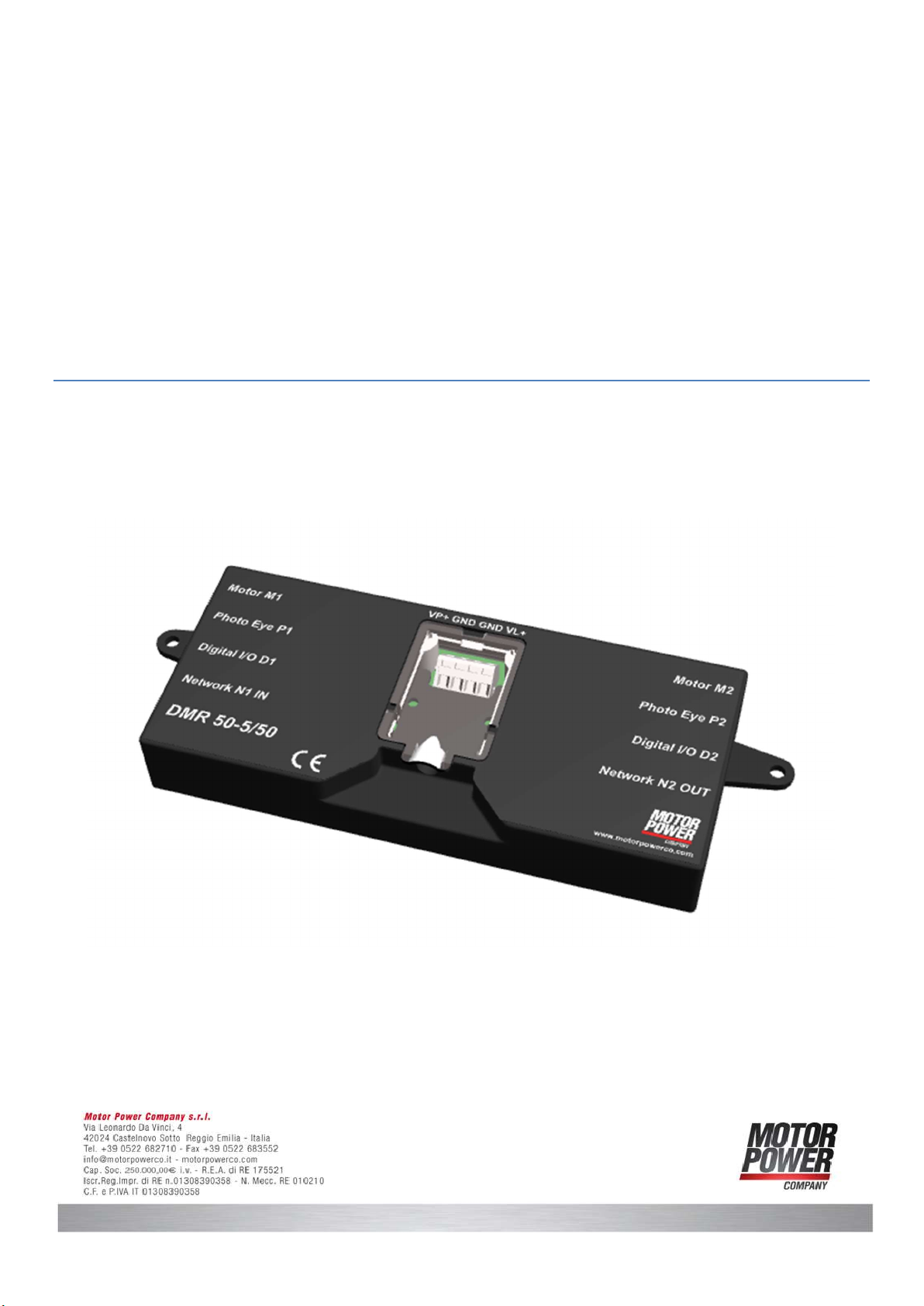
2 Product Presentation .................................................................................................................... 4
2.1 General Description ............................................................................................................... 4
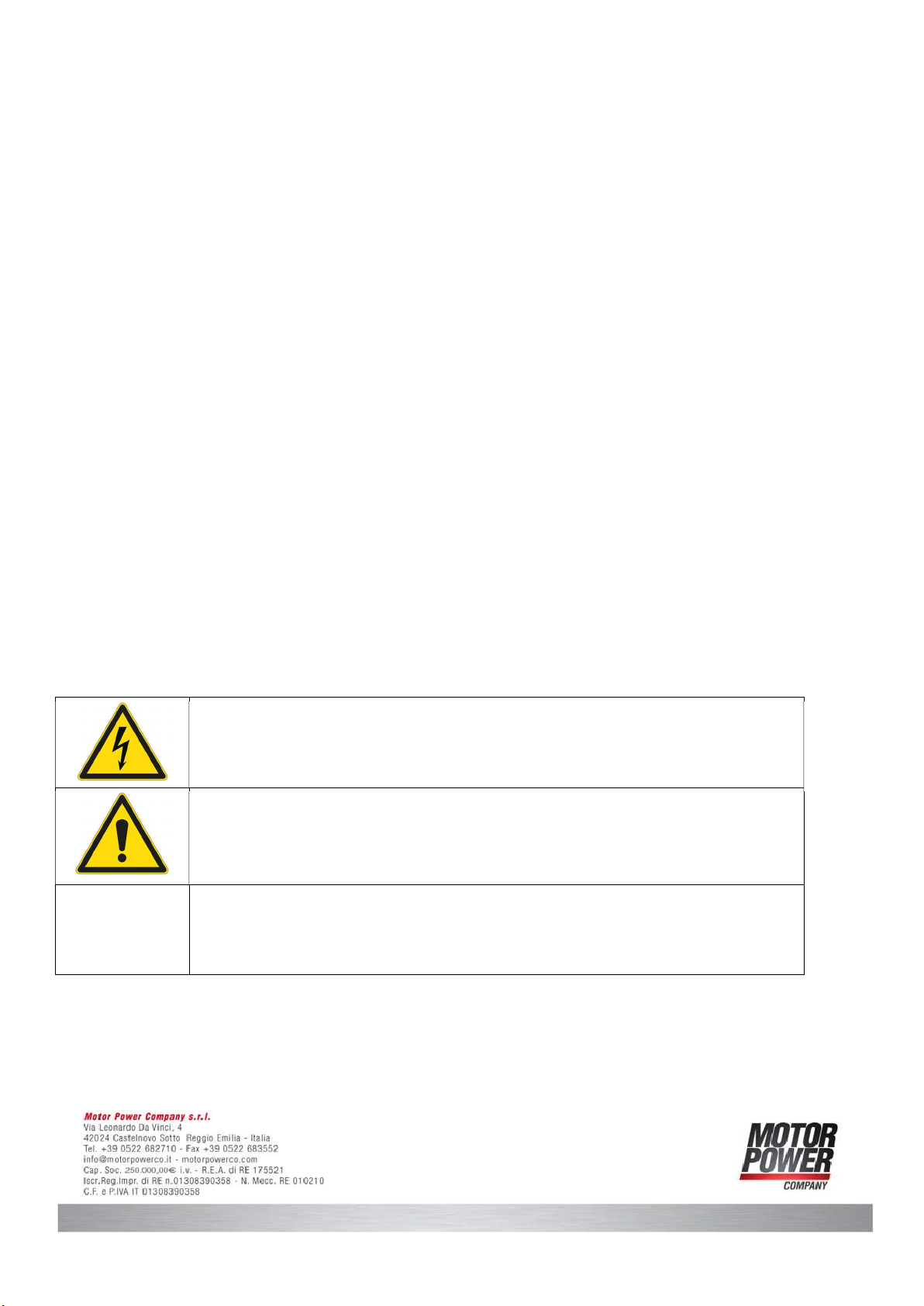
3 Safety Information ....................................................................................................................... 5
3.1 Warnings .............................................................................................................................. 6
3.2 Cautions ............................................................................................................................... 7
3.3 Directives and Standards ........................................................................................................ 8
3.4 CE Mark Conformance ............................................................................................................ 8
3.5 Warranty Information ............................................................................................................ 8
3.6 Drawings .............................................................................................................................. 9
3.7 Typical Installation ................................................................................................................. 9
3.8 Specifications ...................................................................................................................... 10
3.9 Environmental Conditions ..................................................................................................... 10
3.10 Available Models .................................................................................................................. 11
3.10.1 Type Plate .................................................................................................................... 11
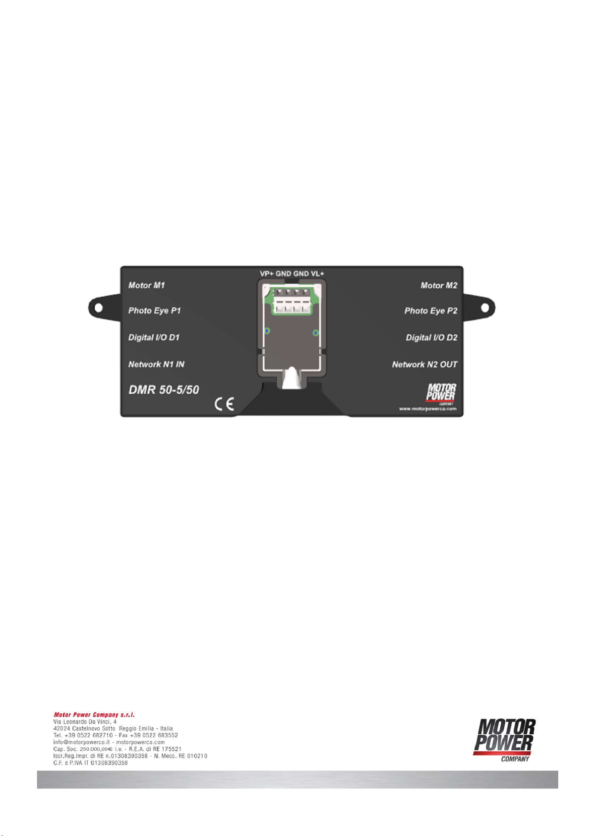
4 Location of Items ....................................................................................................................... 12
5 Wiring ....................................................................................................................................... 13
5.1 Connector XP1 – Power Supply ............................................................................................. 13
5.2 Connector M1, M2 – Motor Connector ................................................................................... 14
5.3 Connector P1, P2 - Photo Eye Connector ............................................................................... 15
5.3.1 Photo Eye internal connection ........................................................................................ 15
5.4 Connector D1, D2 - Standard Function Connector ................................................................... 16
5.4.1 Digital Input internal wiring ............................................................................................ 17
5.4.2 Analog Input internal wiring ........................................................................................... 17
5.4.3 Digital Output Internal wiring ......................................................................................... 18
5.5 Connector N1,N2 - Network Connection ................................................................................. 19
6 Connection schematic ................................................................................................................. 20
6.1 Schematic circuit for power and logic supply ......................................................................... 21
7 Default I/O Functionality ............................................................................................................. 21
7.1 Run/Stop ............................................................................................................................ 21

DMR 50-5/50 Installation Guide V3.0 Pag. 3
7.2 DIR – Direction of Rotation ................................................................................................... 23
7.3 V-IN – Speed Variation ......................................................................................................... 23
7.4 ERR – Error Signal ............................................................................................................... 24
7.5 Customized I/O configuration ............................................................................................... 24
8 LED Configuration ...................................................................................................................... 25
8.1 LED Map ............................................................................................................................. 25
8.2 L1 and L2 Axis Status ........................................................................................................... 26
8.3 L3 Auxiliary Power Supply Status .......................................................................................... 26
8.4 L5 Device Status .................................................................................................................. 26
9 Information on the motor ........................................................................................................... 27
9.1 Motor Phase Angle ............................................................................................................... 27
9.2 Hall signal sequence ............................................................................................................ 28
9.3 Motor Phase Sequence ......................................................................................................... 29
10 Standard Configuration Interface ................................................................................................. 30
10.1 Setup for Modbus RTU ......................................................................................................... 30
10.2 Standard communication parameters .................................................................................... 32
Notice:
This guide delivered subject to the following conditions and restrictions: This guide contains proprietary
information belonging to Motor power Company Srl. Such information is supplied solely for the purpose of
assisting users of the DMR 50-5/50 servo drive in its installation and configuration.
The text and graphics included in this manual are for the purpose of illustration and reference only. The
specifications on which they are based are subject to change without notice.
Motor power Company and the Motor power Company logo are trademarks of Motor power Company Srl.
Information in this document is subject to change without notice.
Version Date Author Note
1.0
01/11/2018
Maurizio Piccinelli
Initial Release
2.0 15/06/2020 Maurizio Piccinelli Few updates
3.0
18/08/2021
Piccinelli, Piacentini, Zivieri
, Bassoli
LED, RS485 User Interface

DMR 50-5/50 Installation Guide V3.0 Pag. 4
2 Product Presentation
2.1 General Description
The DMR 50-50/50 is a Motoroller servo drive especially designed for Motor Power Company Gearless
motoroller.
We have different available versions with different Digital I/O configuration (PNP,NPN)
The Device is able to operate one or 2 different devices independently, and is compatible with all the size
46 Gearless Motoroller.

DMR 50-5/50 Installation Guide V3.0 Pag. 5
3 Safety Information
In order to achieve the optimum, safe operation of the MDR servo drive, it is imperative that you
implement the safety procedures included in this installation guide. This information is provided to protect
you and to keep your work area safe when operating the MDR and accompanying equipment. Please read
this chapter carefully before you begin the installation process. Before you start, ensure that all system
components are connected to earth ground.
Electrical safety is provided through a low-resistance earth connection. Only qualified personnel may install,
adjust, maintain and repair the servo drive. A “qualified person” has the knowledge and authorization to
perform tasks such as transporting, assembling, installing, commissioning and operating motors.
The DMR servo drive contains electrostatic-sensitive components that can be damaged if handled
incorrectly. To prevent any electrostatic damage, avoid contact with highly insulating materials, such as
plastic film and synthetic fabrics. Place the product on a conductive surface and ground yourself in order to
discharge any possible static electricity build-up. To avoid any potential hazards that may cause severe
personal injury or damage to the product during operation, keep all covers and cabinet doors shut. The
following safety symbols are used in this manual:
Warning:
This information is needed to avoid a safety hazard, which might cause bodily
injury.
Caution:
This information is necessary for preventing damage to the product or to other
equipment.
Note:
This is auxiliary information that ensures the correct operation of the
equipment.

DMR 50-5/50 Installation Guide V3.0 Pag. 6
3.1 Warnings
To avoid electric hazards to personnel and electrical contacts, never
connect/disconnect the servo drive while the power source is on.
Power cables can carry a high voltage, even when the motor is not in motion.
Disconnect the DMR 50-50/50 from all voltage sources before it is open
for
servicing.
The DMR 50-50/50
servo drive contains grounding conduits for electric current
protection. Any disruption to these conduits may cause the device to become
“hot” (live) and dangerous.
After shutting off the power and removing the power source from your
equipment, wait at least 3 minute before touching or
disconnecting parts of
the equipment that are normally loaded with electrical charges (such as
capacitors or contacts). Measuring the electrical contact points with a meter
before touching the equipment is recommended.

DMR 50-5/50 Installation Guide V3.0 Pag. 7
3.2 Cautions
The DMR 50-50/50 servo drive contains hot surfaces and electrically-
charged
components during operation.
The maximum DC
power supply connected to the instrument must comply with
the parameters outlined in this guide.
The DMR 50-50/50
servo drive must be connected to an approved 24VDC
auxiliary power supply through a line that is separated from hazardous line
voltages us
ing reinforced or double insulation in accordance with approved
safety standards.
The DMR 50-50/50 series is designed to gets its power from a 48 VDC
power
source. Power to this device must be
supplied by DC voltage, within the
boundaries specified for the DMR. High voltages may damage the dri
ve. The
DC power supply voltage
range is defined in this manual. Safety margins must
be considered in order to avoid activating the under or over-
voltage protection
against line variations and/or volta
ge drop under load. The transformer should
be able to deliver the required power to the drive (including peak power)
without significant voltage drops (10% maximum). While driving high-
inertia
loads, the power supply circuit must be equipped with a shunt r
egulator;
otherwise, the drive will be disabled whenever the capacitors are charged
above the maximum voltage
Before switching on the DMR
, verify that all safety precautions have been
observed and that the installation procedures in this manual have
been
followed.

DMR 50-5/50 Installation Guide V3.0 Pag. 8
3.3 Directives and Standards
The DMR 50-5/50 servo drive conforms to the following industry safety standards:
Safety Standard Item
Designed in Compliance with UL508c
and UL840
Conformance to the following safety
standards:
• Power Conversion Equipment
• Insulation Coordination, Including
Clearance and Creepage distances of
electrical equipment
Designed in compliance with UL60950
(formerly UL1950)
Safety of Information Technology Equipment,
Including Electrical Business Equipment
In compliance with EN60204-1 Low Voltage Directive, 73/23/EEC
3.4 CE Mark Conformance
The DMR 50-5/50 servo drive is intended for incorporation in a machine or end product. The actual end
product must comply with all safety aspects of the relevant requirements of the European Safety of Machinery
Directive 98/37/EC as amended, and with those of the most recent versions of standards EN60204-1 and
EN292-2 at the least.
According to Annex III of Article 13 of Council Directive 93/68/EEC, amending Council Directive 73/23/EEC
concerning electrical equipment designed for use within certain voltage limits, the DMR 50-50/50 meets the
provisions outlined in Council Directive 73/23/EEC. The party responsible for ensuring that the equipment
meet the limits required by EMC regulations is the manufacturer of the end product.
3.5 Warranty Information
The products covered in this manual are warranted to be free of defects in material and workmanship and
conform to the specifications stated either within this document or in the product catalogue description. All
Motor Power Company products are warranted for a period of 12 months from the time of shipment. No
other warranties, expressed or implied — and including a warranty of merchantability and fitness for a
particular purpose — extend beyond this warranty.

DMR 50-5/50 Installation Guide V3.0 Pag. 9
3.6 Drawings
3.7 Typical Installation
The device is designed to be installed on conveyor side
Figure 1:Typical Installation inside side channel
To fix the device to the conveyor side 2 x M5 screw are necessary.

DMR 50-5/50 Installation Guide V3.0 Pag. 10
3.8 Specifications
Description
Logic
Supply
24 Vdc +/
-
5%
Minimum Supply Voltage 12 Vdc
Nominal Supply Voltage 48 Vdc
Maximum Supply Voltage
60 Vdc
Nominal Current 4 A
Pe
a
k Current
15 A
Output Power 240 W
Efficiency @ rated Power > 90%
PWM Switching Frequency
10 kHz
(Max)
Weight Kg
Dimensions 242x86x27 mm
Mounting Model
Wall Mount on Back side
3.9 Environmental Conditions
Description
Operating ambient temperature 0° ~ 40° C (32° ~ 104° F)
Storage temperature
-
20° ~ +85° C (
-
4° ~ +185° F)
Humidity 90% maximum non-condensing
Protection level IP20

DMR 50-5/50 Installation Guide V3.0 Pag. 11
3.10 Available Models
Part Number
Description
Note
051700000001 DMR 50-5/50 E C 0 PNP - Available on Request
051700000002
DMR 50
-
5/50 E C 1
NPN
-
Available on Request
051700000003 DMR 50-5/50 H C 0 PNP - Standard Configuration
051700000004 DMR 50-5/50 H C 1 NPN - Available on Request
3.10.1 Type Plate

DMR 50-5/50 Installation Guide V3.0 Pag. 12
4 Location of Items
To use correctly the device the following items have to be identified:
Object
Description
XP1 Power Supply Connector
M1,M2 Motor Connector
P1,P2
Photo Eye Connector
D1,D2 Function Connector
N1,N2
Network Connector
L1,L2 Led for Motor1 and Motor2
L3 24V Auxiliary Logic
L4,L5
RJ45 LED

DMR 50-5/50 Installation Guide V3.0 Pag. 13
5 Wiring
5.1 Connector XP1 – Power Supply
The Connector Type is WAGO 236-404
The recommended power wires are fine-stranded conductor with ferrule plastic collar 0,25-1,5 mm2
Pin Function Description
1 VP+ Power Supply 48Vdc
2
GND
0 Vdc
3 GND 0 Vdc
4 VL+ Logic Supply 24Vdc
48 V dc switched-mode power supply, which can accept an overcurrent to handle the peak for 3 to 5s is
recommended.
The 24 Vdc Logic supply is protected with a 1 A fuse.
Please provide a power supply that
has
enough power to in
support the application
.
Use Different power supply for Logic and Power. Motor Regeneration can damage the
24V Input Logic.
To avoid Voltage Drop please use always the maximum allowed wire size.

DMR 50-5/50 Installation Guide V3.0 Pag. 14
5.2 Connector M1, M2 – Motor Connector
The connector is JST S09B-XASK-1, the mating connector on motor cable is JST XHP-9.
Pin
Function
Description
1 Mw Motor Phase w
2
Mv
Motor Phase v
3 Mu Motor Phase u
4 Gnd 0 Vdc
5
Hu
Hall Sensor u
6 Hv Hall Sensor v
7 Hw Hall Sensor w
8
Encoder Power Supply
5 Vdc
9 Thermal Sensor NTC Thermal sensor Input
Figure 2: Motor Connector
Extension cables longer than 2 meters can cause voltage drops or distortions of the
feedback signals. The device could not work properly.

DMR 50-5/50 Installation Guide V3.0 Pag. 15
5.3 Connector P1, P2 - Photo Eye Connector
The connector is Phoenix Contact MC 1,5/ 3-G-3,5 – 1844223, the mating connector is Phoenix Contact MC
1,5/ 3-ST-3,5 – 1840379.
Pin
Function
Description
1 Power Supply 24 V power supply 200mA
2 Photo Eye Input Input signal
3
Gnd
0 Vdc
Figure 3: Photo Eye Connector
5.3.1 Photo Eye internal connection
1ms tau
76K8 1%
10K 1%
GND
0.1uF 16V
3K3
GND
R25
R28
C4
R26
EXT-FOTO FOTO

DMR 50-5/50 Installation Guide V3.0 Pag. 16
5.4 Connector D1, D2 - Standard Functions Connector
The connector is Phoenix Contact MC 1,5/ 5-G-3,5 – 1844249, the mating connector is Phoenix Contact MC
1,5/ 5-ST-3,5 – 1840395.
Pin Function Description Type
1 Enable Enable the Motor Digital Input
2
Dir
Direction of Motor
Digital Input
3 Speed Velocity of the motor Analog Input
4 Error Error on Motor Digital Output
5
Out1
Out1
Digital Output
Figure 4: Standard Functions Connector

DMR 50-5/50 Installation Guide V3.0 Pag. 17
5.4.1 Digital Input internal wiring
Typical input current @24Vcd is 7,2 mA
5.4.2 Analog Input internal wiring
BAV99S
BAV99S
+24V
GND
JP2
1
2
3
D2-2
D2-1
INPUT_RAIL
SFH6206-3
SFH6206-3
3K3
3K3
3K3
1uF 6.3V
+5V
+5V
3K3
1uF 6.3V
GND
470R470R
OK1
1
2 3
4
OK2
1
2 3
4
R1
R2
R3
C10
R4
C1
R6R8
EXT-ENABLE
EXT-DIR
DIR
ENABLE
3 ms tau
3 ms tau
4K02 1%
1K 1%
1uF 6.3V
GND AGND
R17
R18
C2
SPEED010EXT-SPEED010

DMR 50-5/50 Installation Guide V3.0 Pag. 18
5.4.3 Digital Output Internal wiring
The output maximum current have to be < 25 mA. To protect the output is suggested to add an external
resistance R > 860 Ω.
In the event of a current ≥ 25 mA, there is a risk to damage the output transistor.
MMBT3904
MMBT3906
100R
820R
+24V
MMBT3904 MMBT3906
10K10K
47K
GND
GND
10K
10K
10K
T1
T2
R9
R10
T3 T4
R11R12
R13
R14
R16
R15
NPN_OUT
PNP_OUT
EXT-OUT
25 mA max

DMR 50-5/50 Installation Guide V3.0 Pag. 19
5.5 Connector N1,N2 - Network Connection
The Connector is a standard RJ45 Female connector, Mating Connector RJ45 Male, is strongly recommended
to use connector with metal case.
Pin
Function
Description
Standard RJ
-
45 cable color
1 CAN H CAN High White/Orange
2 CAN L CAN Low Orange
3
----
Not Connected
White/Green
4 DATA+ RS 485 DATA+ Blue
5 DATA- RS 485 DATA- White/Blue
6
Shield
Shield
Green
7 NC Not Connected White Brown
8 DI/DO Input on N1, Output on N2 Brown
To operate correctly the CAN Bus or the RS485 communications a 120Ω termination
resistance must be added at both line side.
Figure 5: Network Connector

DMR 50-5/50 Installation Guide V3.0 Pag. 20
6 Connection schematic
Warning:
Before commissioning, it is essential that the safety instructions in the relevant section
are read and understood, and then observed!
Non-observance can result in danger to persons or damage to the equipment.
Disconnect the electrical power supply before any operation on the device.
CAUTION:
Incorrect connection of motor power electronics.
The motor is not equipped with reverse polarity protection.
Consequence:
Destroying of the power electronics possible.
Check the right polarity
.
NOTICE:
Loops must be avoided for all grounding concepts. Shielded cable must be used for the
whole cable system without interruption. Up to a length of 10m a common power and
signal cable can be used. If the cable is longer than 10m it is recommended to separate
power and signal in different shielded cables. When standard wires from Motor Power
Company are used, the shielding must be spaciously applied inside the control cabinet.
Failure to follow them can result in danger to persons or damage to the equipment.
This manual suits for next models
1
Table of contents
Other Motor Power Company Servo Drive manuals

Motor Power Company
Motor Power Company Duet AD 80 User manual

Motor Power Company
Motor Power Company DUET_FL 48/10 User manual

Motor Power Company
Motor Power Company FLEXI PRO Series User manual

Motor Power Company
Motor Power Company DUET AD Series User manual

Motor Power Company
Motor Power Company DMR 50-5/50 V3.0 User manual