manuals.online logo
Brands
  1. Home
  2. •
  3. Brands
  4. •
  5. Omron
  6. •
  7. Servo Drive
  8. •
  9. Omron SMARTSTEP 2 R88M-G Series User manual

Omron SMARTSTEP 2 R88M-G Series User manual

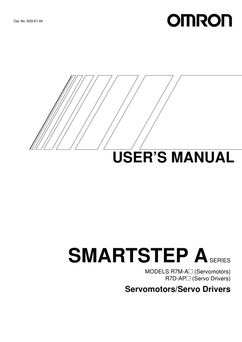
Cat. No. I561-E1-06
USER’S MANUAL
SMARTSTEP 2SERIES
R88M-G@
(Servomotors)
R7D-BP@
(Servo Drives)
SERVOMOTORS/SERVO DRIVES
Trademarks and Copyrights
•
©OMRON, 2008
All rights reserved. No part of this publication may be reproduced, stored in a retrieval system, or transmitted, in any
form, or by any means, mechanical, electronic, photocopying, recording, or otherwise, without the prior written permis-
sion of OMRON.
No patent liability is assumed with respect to the use of the information contained herein. Moreover, because OMRON is
constantly striving to improve its high-quality products, the information contained in this manual is subject to change
without notice. Every precaution has been taken in the preparation of this manual. Nevertheless, OMRON assumes no
responsibility for errors or omissions. Neither is any liability assumed for damages resulting from the use of the informa-
tion contained in this publication.
Product names and system names in this manual are trademarks or registered trademarks of their
respective companies.
1
Introduction
Introduction
Thank you for choosing the SMARTSTEP 2 Series. This User’s Manual describes installation/wiring
methods and parameter setting procedures required for the operation of the SMARTSTEP 2 Series
as well as troubleshooting and inspection methods.
Intended Readers
This manual is intended for the following personnel.
Those with knowledge of electrical systems (a qualified electrical engineer or the equivalent) as
follows:
Personnel in charge of introducing FA equipment
Personnel in charge of designing FA systems
Personnel in charge of managing FA systems and facilities
NOTICE
This manual contains information necessary to ensure safe and proper use of the SMARTSTEP 2
Series and its peripheral devices. Please read this manual thoroughly and understand its contents
before using the products.
Please keep this manual handy for future reference.
Make sure this User’s Manual is delivered to the actual end user of the products.
2
Terms and Conditions Agreement
Exclusive Warranty
Omron’s exclusive warranty is that the Products will be free from defects in materials and
workmanship for a period of twelve months from the date of sale by Omron (or such other
period expressed in writing by Omron). Omron disclaims all other warranties, express or
implied.
Limitations
OMRON MAKES NO WARRANTY OR REPRESENTATION, EXPRESS OR IMPLIED,
ABOUT NON-INFRINGEMENT, MERCHANTABILITY OR FITNESS FOR A PARTICULAR
PURPOSE OF THE PRODUCTS. BUYER ACKNOWLEDGES THAT IT ALONE HAS
DETERMINED THAT THE PRODUCTS WILL SUITABLY MEET THE REQUIREMENTS OF
THEIR INTENDED USE.
Omron further disclaims all warranties and responsibility of any type for claims or expenses
based on infringement by the Products or otherwise of any intellectual property right.
Buyer Remedy
Omron’s sole obligation hereunder shall be, at Omron’s election, to (i) replace (in the form
originally shipped with Buyer responsible for labor charges for removal or replacement
thereof) the non-complying Product, (ii) repair the non-complying Product, or (iii) repay or
credit Buyer an amount equal to the purchase price of the non-complying Product; provided
that in no event shall Omron be responsible for warranty, repair, indemnity or any other claims
or expenses regarding the Products unless Omron’s analysis confirms that the Products were
properly handled, stored, installed and maintained and not subject to contamination, abuse,
misuse or inappropriate modification. Return of any Products by Buyer must be approved in
writing by Omron before shipment. Omron Companies shall not be liable for the suitability or
unsuitability or the results from the use of Products in combination with any electrical or elec-
tronic components, circuits, system assemblies or any other materials or substances or envi-
ronments. Any advice, recommendations or information given orally or in writing, are not to be
construed as an amendment or addition to the above warranty.
See http://www.omron.com/global/ or contact your Omron representative for published informa-
tion.
OMRON COMPANIES SHALL NOT BE LIABLE FOR SPECIAL, INDIRECT, INCIDENTAL, OR
CONSEQUENTIAL DAMAGES, LOSS OF PROFITS OR PRODUCTION OR COMMERCIAL
LOSS IN ANY WAY CONNECTED WITH THE PRODUCTS, WHETHER SUCH CLAIM IS
BASED IN CONTRACT, WARRANTY, NEGLIGENCE OR STRICT LIABILITY.
Further, in no event shall liability of Omron Companies exceed the individual price of the Product
on which liability is asserted.
Warranty, Limitations of Liability
Warranties
Limitation on Liability; Etc
3
Omron Companies shall not be responsible for conformity with any standards, codes or regula-
tions which apply to the combination of the Product in the Buyer’s application or use of the Prod-
uct. At Buyer’s request, Omron will provide applicable third party certification documents
identifying ratings and limitations of use which apply to the Product. This information by itself is
not sufficient for a complete determination of the suitability of the Product in combination with the
end product, machine, system, or other application or use. Buyer shall be solely responsible for
determining appropriateness of the particular Product with respect to Buyer’s application, prod-
uct or system. Buyer shall take application responsibility in all cases.
NEVER USE THE PRODUCT FOR AN APPLICATION INVOLVING SERIOUS RISK TO LIFE
OR PROPERTY WITHOUT ENSURING THAT THE SYSTEM AS A WHOLE HAS BEEN
DESIGNED TO ADDRESS THE RISKS, AND THAT THE OMRON PRODUCT(S) IS PROPERLY
RATED AND INSTALLED FOR THE INTENDED USE WITHIN THE OVERALL EQUIPMENT OR
SYSTEM.
Omron Companies shall not be responsible for the user’s programming of a programmable Prod-
uct, or any consequence thereof.
Data presented in Omron Company websites, catalogs and other materials is provided as a
guide for the user in determining suitability and does not constitute a warranty. It may represent
the result of Omron’s test conditions, and the user must correlate it to actual application require-
ments. Actual performance is subject to the Omron’s Warranty and Limitations of Liability.
Product specifications and accessories may be changed at any time based on improvements
and other reasons. It is our practice to change part numbers when published ratings or features
are changed, or when significant construction changes are made. However, some specifications
of the Product may be changed without any notice. When in doubt, special part numbers may be
assigned to fix or establish key specifications for your application. Please consult with your
Omron’s representative at any time to confirm actual specifications of purchased Product.
Information presented by Omron Companies has been checked and is believed to be accurate;
however, no responsibility is assumed for clerical, typographical or proofreading errors or omis-
sions.
Application Considerations
Suitability of Use
Programmable Products
Disclaimers
Performance Data
Change in Specifications
Errors and Omissions
4
Precautions for Safe Use
To ensure safe and proper use of the SMARTSTEP 2 Series and its peripheral devices, read the “Precautions
for Safe Use” and the rest of the manual thoroughly to acquire sufficient knowledge of the devices, safety
information, and precautions before using the products.
Make sure this User’s Manual is delivered to the actual end users of the products.
Please keep this manual close at hand for future reference.
Explanation of Signal Words
The precautions indicated here provide important information for safety. Be sure to heed the information
provided with the precautions.
The following signal words are used to indicate and classify precautions in this manual.
Failure to heed the precautions classified as “Caution” may also lead to serious results. Strictly heed
these precautions.
Safety Precautions
This manual may include illustrations of the product with protective covers or shields removed in order to show
the components of the product in detail. Make sure that these protective covers and shields are put in place as
specified before using the product.
Consult your OMRON representative when using the product after a long period of storage.
Always connect the frame ground terminals of the Servo Drive and the Servomotor to 100 Ω
or less.
Not doing so may result in electric shock.
Do not touch the inside of the Servo Drive.
Doing so may result in electric shock.
When turning OFF the main circuit power supply, turn OFF the RUN Command Input (RUN)
at the same time. Residual voltage may cause the Servomotor to continue rotating and result
in injury or equipment damage even if the main circuit power supply is turned OFF externally,
e.g., with an emergency stop.
Do not remove the front cover, terminal covers, cables, or optional items while the power is
being supplied.
Doing so may result in electric shock.
WARNING
Caution
Indicates a potentially hazardous situation which, if not
avoided, could result in death or serious injury.
Additionally, there may be severe property damage.
Indicates a potentially hazardous situation which, if not
avoided, may result in minor or moderate injury,
or property damage.
WARNING
5
Precautions for Safe Use
Installation, operation, maintenance, or inspection must be performed by authorized
personnel only.
Not doing so may result in electric shock or injury.
Wiring or inspection must not be performed for at least 15 minutes after turning OFF the
power supply.
Doing so may result in electric shock.
Do not damage, pull on, put excessive stress on, or put heavy objects on the cables.
Doing so may result in electric shock, stopping product operation, or burning.
Do not touch the rotating parts of the Servomotor during operation.
Doing so may result in injury.
Do not modify the product.
Doing so may result in injury or damage to the product.
Provide a stopping mechanism on the machine side to ensure safety.
*The holding brake is not designed as a stopping mechanism for safety purposes.
Not doing so may result in injury.
Provide an external emergency stopping mechanism that can stop operation and shut off the
power supply immediately.
Not doing so may result in injury.
Do not come close to the machine immediately after resetting momentary power interruption
to avoid danger due to an unexpected restart.
Doing so may result in injury.
Take precautions to secure safety in case of an unexpected restart.
Confirm safety after an earthquake has occurred.
Not doing so may result in electric shock, injury, or fire.
Do not use external force to drive the Servomotor.
Doing so may result in fire.
6
Precautions for Safe Use
Storage and Transportation Precautions
Do not place any flammable materials near the Servomotor, Servo Drive, or Regeneration
Resistor.
Doing so may result in fire.
Mount the Servomotor, Servo Drive, and Regeneration Resistor on metal or other non-
flammable materials.
Not doing so may result in fire.
Do not turn ON/OFF the main power supply of the Servo Drive repeatedly at frequent
intervals.
Doing so may result in product failure.
Use the Servomotors and Servo Drives in a combination as specified in the manual.
Not doing so may result in fire or damage to the products.
Do not store or install the product in the following places. Doing so may result in fire, electric
shock, or damage to the product.
Locations subject to direct sunlight.
Locations subject to ambient temperature exceeding the specified level.
Locations subject to relative humidity exceeding the specified level.
Locations subject to condensation due to temperature fluctuations.
Locations subject to corrosive or flammable gases.
Locations subject to dust (especially iron dust) or salt.
Locations subject to exposure to water, oil, or chemicals.
Locations subject to shock or vibration.
Do not touch the Servo Drive radiator, Regeneration Resistor, or Servomotor while the
power is being supplied or for some time after the power is turned OFF.
Doing so may result in burn injuries.
Do not hold the product by the cables or motor shaft while transporting it.
Doing so may result in injury or malfunction.
Do not overly pile the products. (Follow the instructions on the product package.)
Doing so may result in injury or malfunction.
WARNING
Caution
Caution
7
Precautions for Safe Use
Installation and Wiring Precautions
Do not step on or place a heavy object on the product.
Doing so may result in injury.
Do not cover the inlet/outlet ports and do not let any foreign objects enter the product.
Doing so may result in fire.
Be sure to install the product in the correct direction.
Not doing so may result in malfunction.
Keep the specified distance between the Servo Drive and the control panel or with other
devices.
Not doing so may result in fire or malfunction.
Do not apply a strong impact on the Servomotor shaft or Servo Drive.
Doing so may result in malfunction.
Be sure to wire correctly and securely.
Not doing so may result in motor runaway, injury, or malfunction.
Be sure that all the mounting screws, terminal block screws, and cable connector screws are
tightened securely.
Not doing so may result in malfunction.
Use crimp terminals for wiring.
Do not connect bare stranded wires directly to the protective ground terminal.
Doing so may result in fire.
Always use the power supply voltage specified in the User’s Manual.
Not doing so may result in malfunction or burning.
Take appropriate measures to ensure that the specified power with the rated voltage and
frequency is supplied. Use particular caution if the product is used in a place where a stable
power supply cannot be provided.
Not doing so may result in equipment damage.
Install breakers and take other safety measures against short-circuiting of external wiring.
Not doing so may result in fire.
Take sufficient shielding measures when using the product in the following locations.
Not doing so may result in damage to the product.
Locations subject to static electricity or other forms of noise.
Locations subject to strong electromagnetic fields and magnetic fields.
Locations subject to possible exposure to radioactivity.
Locations close to power lines.
Connect an emergency stop shutoff relay in series with the brake control relay.
Not doing so may result in injury or product failure.
Caution
8
Precautions for Safe Use
Operation and Adjustment Precautions
Maintenance and Inspection Precautions
Confirm that no adverse effects will occur in the system before performing the test operation.
Not doing so may result in equipment damage.
Check that the newly set parameters function properly before the actual operation.
Not doing so may result in equipment damage.
Do not make any extreme adjustments or setting changes.
Doing so may result in injury.
Check for the proper operation of the Servomotor separately from the mechanical system
before connecting it to the machine.
Not doing so may cause injury.
When an alarm occurs, remove the cause, reset the alarm after confirming safety, and then
resume operation.
Not doing so may result in injury.
Do not use the built-in brake of the Servomotor for ordinary braking.
Doing so may result in malfunction.
Do not operate the Servomotor connected to a load that exceeds the applicable load inertia.
Doing so may result in malfunction.
Resume operation only after transferring to the new Unit the contents of the data required
for operation restart.
Not doing so may result in equipment damage.
Do not dismantle or repair the product.
Doing so may result in electric shock or injury.
Caution
Caution
9
Precautions for Safe Use
Warning Label Position
Warning labels are located on the product as shown in the following illustration.
Be sure to follow the instructions given there.
Warning Label Contents
Disposing of the Product
Dispose of the product as industrial waste.
Warning label
(Example of R7D-BP01H)
PWR
ALM
C
N
3
C
N
1
C
N
2
C
N
B
C
N
A
10
Items to Check When Unpacking
Check the following items after removing the product from the package.
Has the correct product been delivered?
Has the product been damaged in shipping?
Accessories Provided with Product
Safety Precautions document ×1
No connectors or mounting screws are provided. They have to be prepared by the user.
Should you find any problems (missing parts, damage to the Servo Drive, etc.), please contact
your local sales representative or OMRON sales office.
Understanding Model Numbers
Servo Drive Models
The model number provides information such as the Servo Drive type, the applicable
Servomotor capacity, and the power supply voltage.
R7D-BP01H
SMARTSTEP 2
Servo Drive
Applicable Servomotor
Capacity
Power Supply Voltage
Drive Type
P: Pulse-string input type
A5: 50 W
01: 100 W
02: 200 W
04: 400 W
L: 100 VAC
H: Single/Three-phase 200 VAC
HH: Single-phase 200 VAC
Note Single phase: Haploid phase
11
Items to Check When Unpacking
Servomotor Models
The model number provides information such as the Servomotor type, Servomotor capacity, rated
rotation speed, and options.
R88M-GP10030H-BOS2
Servomotor Capacity
Rated Rotation Speed
Motor Type
P: Flat type
050: 50 W
100: 100 W
200: 200 W
400: 400 W
30: 3000 r/min
None: Cylinder type
Power Supply Voltage
H: 200 VAC
L: 100 VAC
Options
None: Straight shaft
B: With brake
O: With oil seal
G-Series Servomotor
S2: With key and tap
12
About this Manual
About this Manual
This manual consists of the following chapters. Refer to this table and choose the required chapters
of the manual.
Overview
Chapter 1 Features and System
Configuration
Describes the features and names of parts of the product as well
as the EC Directives and the UL standards.
Chapter 2 Standard Models and
Dimensions
Provides the model numbers, external and mounted dimensions
for Servo Drives, Servomotors, Decelerators, and peripheral devic-
es.
Chapter 3 Specifications
Provides the general specifications, performance specifications,
connector specifications, and I/O circuit specifications for Servo
Drives and the general specifications and performance specifica-
tions for Servomotors, as well as specifications for accessories
such as encoders.
Chapter 4 System Design
Describes the installation conditions for Servo Drives, Servomo-
tors, and Decelerators, EMC conforming wiring methods, calcula-
tions of regenerative energy, and performance information on the
External Regeneration Resistor.
Chapter 5 Operating Functions Describes the electronic gear function and other operating func-
tions as well as the parameter setting procedure.
Chapter 6 Operation Describes operating procedures and how to use the Parameter
Unit.
Chapter 7 Adjustment Functions Describes realtime autotuning function, manual tuning and other
procedures for gain adjustment.
Chapter 8 Troubleshooting
Describes items to check for troubleshooting, error diagnoses us-
ing alarm displays and the countermeasures, error diagnoses
based on the operation status and the countermeasures, and peri-
odic maintenance.
Appendix Connection Exam-
ples
Provides examples of connection with OMRON PLCs and Position
Controllers.
13
CONTENTS
Introduction .................................................................................. 1
Precautions for Safe Use ............................................................. 4
Items to Check When Unpacking................................................. 10
About this Manual ........................................................................ 12
Chapter 1 Features and System Configuration
1-1 Overview..................................................................................................1-1
1-2 System Configuration ..............................................................................1-2
1-3 Names of Parts and Functions ................................................................1-3
1-4 System Block Diagrams...........................................................................1-5
1-5 Applicable Standards...............................................................................1-6
Chapter 2 Standard Models and Dimensions
2-1 Standard Models......................................................................................2-1
2-2 External and Mounted Dimensions..........................................................2-15
Chapter 3 Specifications
3-1 Servo Drive Specifications.......................................................................3-1
3-2 Servomotor Specifications .......................................................................3-16
3-3 Decelerator Specifications .......................................................................3-26
3-4 Cable and Connector Specifications........................................................3-32
3-5 Servo Relay Units and Cable Specifications ...........................................3-55
3-6 Parameter Unit Specifications .................................................................3-80
3-7 External Regeneration Resistors Specifications......................................3-81
3-8 Reactor Specifications .............................................................................3-82
Chapter 4 System Design
4-1 Installation Conditions..............................................................................4-1
4-2 Wiring.......................................................................................................4-12
4-3 Wiring Conforming to EMC Directives .....................................................4-20
4-4 Regenerative Energy Absorption.............................................................4-35
Chapter 5 Operating Functions
5-1 Position Control .......................................................................................5-1
5-2 Internally Set Speed Control....................................................................5-4
5-3 Forward and Reverse Drive Prohibit........................................................5-7
5-4 Encoder Dividing......................................................................................5-8
5-5 Electronic Gear ........................................................................................5-9
5-6 Brake Interlock.........................................................................................5-11
5-7 Gain Switching.........................................................................................5-13
5-8 Torque Limit.............................................................................................5-15
5-9 Overrun Limit ...........................................................................................5-16
5-10 User Parameters......................................................................................5-17
14
CONTENTS
Chapter 6 Operation
6-1 Operational Procedure ............................................................................ 6-1
6-2 Preparing for Operation........................................................................... 6-2
6-3 Using the Parameter Unit........................................................................ 6-4
6-4 Trial Operation ........................................................................................ 6-22
Chapter 7 Adjustment Functions
7-1 Gain Adjustment...................................................................................... 7-1
7-2 Realtime Autotuning................................................................................ 7-3
7-3 Autotuning ............................................................................................... 7-8
7-4 Disabling the Automatic Gain Adjustment Function ................................ 7-13
7-5 Manual Tuning ........................................................................................ 7-15
Chapter 8 Troubleshooting
8-1 Error Processing ..................................................................................... 8-1
8-2 Alarm Table............................................................................................. 8-3
8-3 Troubleshooting ...................................................................................... 8-5
8-4 Overload Characteristics (Electronic Thermal Function)......................... 8-17
8-5 Periodic Maintenance.............................................................................. 8-18
Chapter 1
Features and System
Configuration
1-1 Overview .............................................................1-1
Overview of the SMARTSTEP 2 Series...................................1-1
Features of the SMARTSTEP 2 Series.................................... 1-1
1-2 System Configuration........................................1-2
1-3 Names of Parts and Functions .........................1-3
Servo Drive Part Names ..........................................................1-3
Servo Drive Functions..............................................................1-4
1-4 System Block Diagrams ....................................1-5
1-5 Applicable Standards ........................................1-6
EC Directives ........................................................................... 1-6
UL/CSA Standards................................................................... 1-6
1-1
1-1 Overview
1
Features and System Configuration
1Feature s and Syste m Configuration
1-1 Overview
Overview of the SMARTSTEP 2 Series
The SMARTSTEP 2 Series is a series of pulse-string input type Servo Drives for position controlling
and it has been designed to function for low-capacity positioning systems. In spite of the compact
size, the SMARTSTEP 2 Series features realtime autotuning and adaptive filter functions that
automatically perform complicated gain adjustments. A notch filter can also be automatically set to
suppress machine vibration by reducing mechanical resonance during operation. The damping
control function of the SMARTSTEP 2 Series realizes stable stopping performance in a mechanism
which vibrates because of the low rigidity of the load.
Features of the SMARTSTEP 2 Series
The SMARTSTEP 2 Series has the following features.
Compact AC Servo Drives
Compared to the SMARTSTEP A Series, the SMARTSTEP 2 Series can reduce the installation
space by 48% and the installation size by 39% in terms of volume. The AC Servo Drives of the
SMARTSTEP 2 Series are equipped with newly developed functions for applications requiring more
precise positioning.
Suppressing Vibration of Low-rigidity Mechanisms during Acceleration/
Deceleration
The damping control function can suppress vibration of low-rigidity mechanisms or devices whose
ends tend to vibrate.
High-speed Positioning via Resonance Suppression Control
The realtime autotuning function automatically estimates the load inertia of the machine in realtime
and sets the optimal gain. The adaptive filter automatically suppresses vibration caused by
resonance.
Compatible with Command Pulse of 90°Phase Difference Inputs
In addition to conventional CW/CCW inputs (2 pulse inputs) and SIGN/PULS inputs (1 pulse input),
the SMARTSTEP 2 supports 90°phase difference inputs. This makes it possible to input encoder
output signals directly into the Servo Drive for simplified synchronization control.
A Wide Range of Pulse Setting Functions
A wide range of pulse setting functions, such as the command pulse multiplying, electronic gear,
and encoder dividing, enable you to perform pulse settings suitable for your device or system.
Simplified Speed Control with Internal Speed Settings
Four internal speed settings allow the speed to be easily switched by using external signals.
Encoder Dividing Output Function
The number of motor encoder pulses output by the Servo Drive can be freely set in the range of 1
to 2,500 pulses per rotation. A parameter can also be set to change the phase.
1-2
1-2 System Configuration
1
Features and System Configuration
1-2 System Configuration
INPUT
AC100
-240V
L2/N
L1
NC
NC
SYSMAC PLC + Position Control
Unit with pulse-string output
SYSMAC
CJ1/CS1/C-Series
Programmable Controller
Position Control Unit
CJ1W-NC113/213/413
CJ1W-NC133/233/433
CS1W-NC113/213/413
CS1W-NC133/233/433
C200HW-NC113/213/413
Pulse string
SYSMAC PLC with pulse output functions
SYSMAC CJ1M
SYSMAC CP1H/CP1L
Flexible Motion Controller with Pulse I/O
FQM1-MMP22
SMARTSTEP 2 Servo Drive
R7D-BP@
OMNUC G-Series Servomotor
R88M-G@/-GP@
1-3
1-3 Names of Parts and Functions
1
Features and System Configuration
1-3 Names of Parts and Functions
Servo Drive Part Names
C
N
1
C
N
2
C
N
A
C
N
B
C
N
3
PWR
ALM
Encoder input connector (CN2)
Motor connector (CNB)
Communications connector (CN3)
Alarm LED indicator (ALM)Power supply LED indicator
FG terminals for
power supply and
Servomotor power Main circuit connector (CNA)
Control I/O connector (CN1)

This manual suits for next models

101

Other Omron Servo Drive manuals

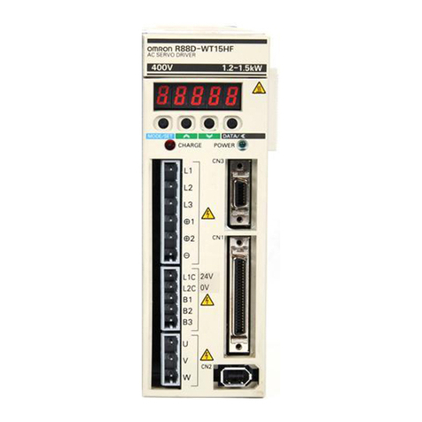
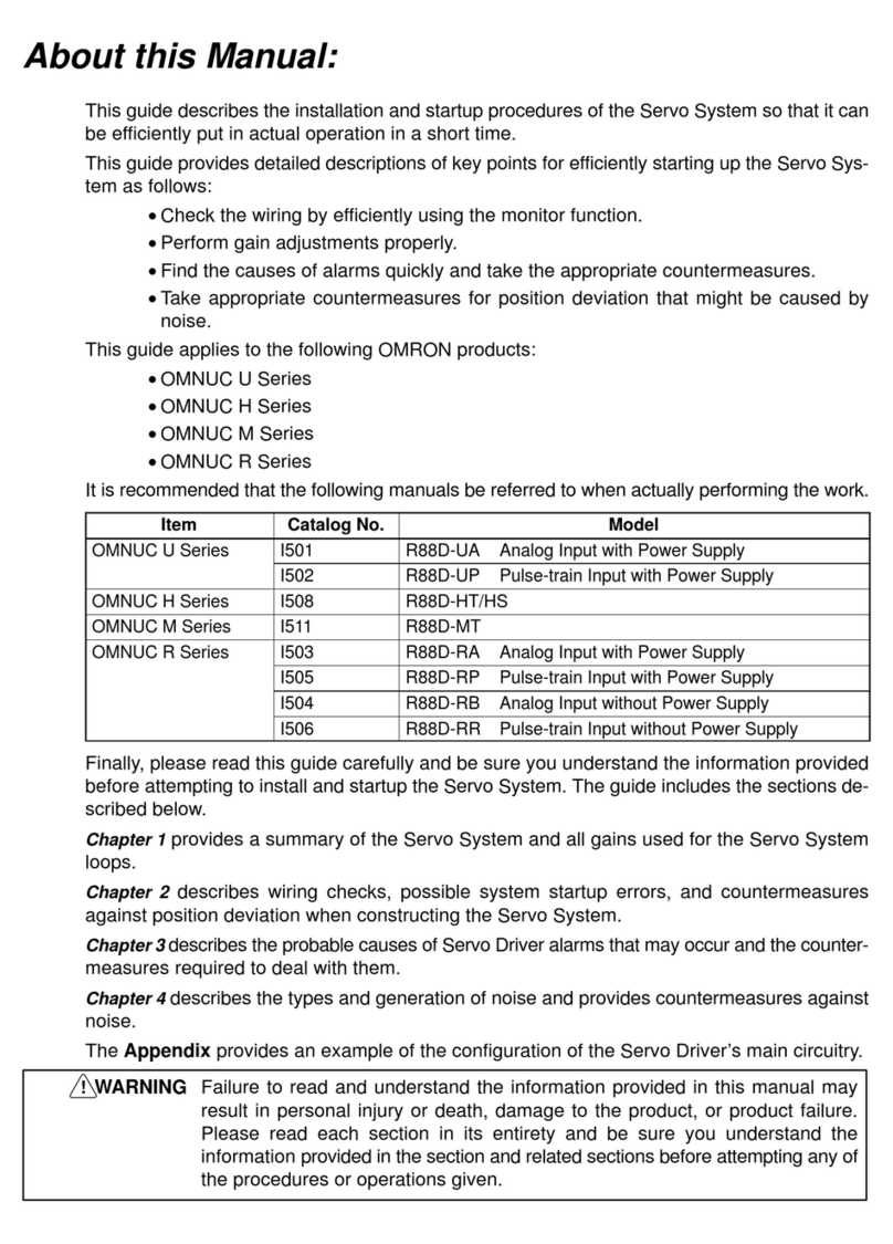
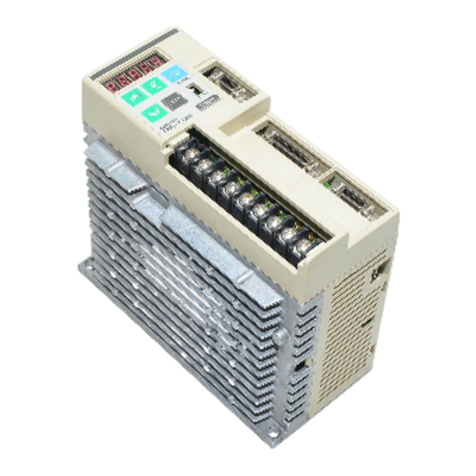
Omron OMNUC R88D-WT15HF User manual

Omron

Omron OMNUC R88D-WT15HF User manual

Omron SMARTSTEP Junior User manual

Omron

Omron SMARTSTEP Junior User manual

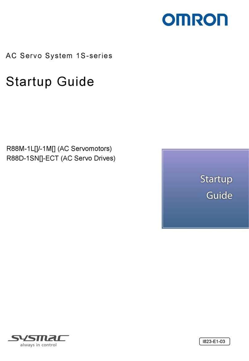
Omron 1S Series User guide

Omron

Omron 1S Series User guide

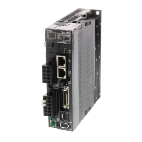
Omron G5 Series User manual

Omron

Omron G5 Series User manual

Omron R88M-1L Series User guide

Omron

Omron R88M-1L Series User guide

Omron JUNMA Series User manual

Omron

Omron JUNMA Series User manual

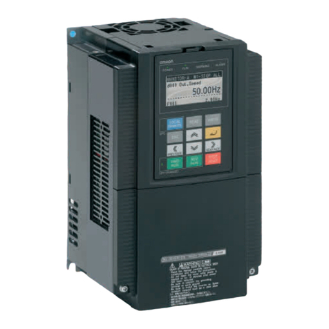
Omron 3G3RX Series User manual

Omron

Omron 3G3RX Series User manual

Omron G User manual

Omron

Omron G User manual

Omron R88M-W User manual

Omron

Omron R88M-W User manual

Omron R88L-EA-AF User manual

Omron

Omron R88L-EA-AF User manual

Omron SMARTSTEP R7M-A Series User manual

Omron

Omron SMARTSTEP R7M-A Series User manual

Omron 1S Series User manual

Omron

Omron 1S Series User manual

Omron R88M-K Series User manual

Omron

Omron R88M-K Series User manual

Omron R88L-EC Series User manual

Omron

Omron R88L-EC Series User manual

Omron R88D-KTA5L User manual

Omron

Omron R88D-KTA5L User manual

Omron R88D-KN ML2 Sries User manual

Omron

Omron R88D-KN ML2 Sries User manual

Omron SMARTSTEP A Series User manual

Omron

Omron SMARTSTEP A Series User manual

Omron OMNUC W Series User manual

Omron

Omron OMNUC W Series User manual

Omron CK M-CPU1 1 Series User guide

Omron

Omron CK M-CPU1 1 Series User guide

Omron OMNUC W Series User manual

Omron

Omron OMNUC W Series User manual

Omron R88D-UA User manual

Omron

Omron R88D-UA User manual

Omron sysmac 1S Series User guide

Omron

Omron sysmac 1S Series User guide

Omron CK5M-CPU 1 Series User guide

Omron

Omron CK5M-CPU 1 Series User guide

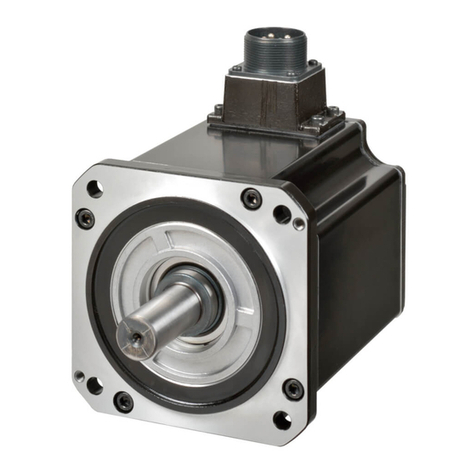
Omron R88M-W60010T User manual

Omron

Omron R88M-W60010T User manual

Popular Servo Drive manuals by other brands

Kinco JD Series user manual

Kinco

Kinco JD Series user manual

Festo DNCI Series operating instructions

Festo

Festo DNCI Series operating instructions

Rockwell Automation Allen-Bradley Kinetix 5500 user manual

Rockwell Automation

Rockwell Automation Allen-Bradley Kinetix 5500 user manual

INVT SV-DA200 Series Technical guide

INVT

INVT SV-DA200 Series Technical guide

LewanSoul LX-16A user manual

LewanSoul

LewanSoul LX-16A user manual

Bosch Rexroth IndraDrive Mi Project planning manual

Bosch

Bosch Rexroth IndraDrive Mi Project planning manual

Superior Electric SLO-SYN TD Series instructions

Superior Electric

Superior Electric SLO-SYN TD Series instructions

Parker PSD1-S quick guide

Parker

Parker PSD1-S quick guide

Lenze AC Tech PositionServo 940 user manual

Lenze

Lenze AC Tech PositionServo 940 user manual

Parker OEM750 user guide

Parker

Parker OEM750 user guide

Fastech S-SERVOII operating manual

Fastech

Fastech S-SERVOII operating manual

EIS OMNUC W Series user manual

EIS

EIS OMNUC W Series user manual

Rockwell Automation Reliance electric GV3000/SE installation manual

Rockwell Automation

Rockwell Automation Reliance electric GV3000/SE installation manual

RHINO MOTION CONTROLS RMCS-1120 Installation Manual and Datasheet

RHINO MOTION CONTROLS

RHINO MOTION CONTROLS RMCS-1120 Installation Manual and Datasheet

Megmeet M5-N Series user manual

Megmeet

Megmeet M5-N Series user manual

Syntec SPD-32C1-075 Hardware manual

Syntec

Syntec SPD-32C1-075 Hardware manual

Astraada SRV-64 Operation manual

Astraada

Astraada SRV-64 Operation manual

Eurotherm Drives 635 product manual

Eurotherm Drives

Eurotherm Drives 635 product manual

manuals.online logo
manuals.online logoBrands
  • About & Mission
  • Contact us
  • Privacy Policy
  • Terms and Conditions

Copyright 2025 Manuals.Online. All Rights Reserved.