Motostar DOMUSTAR User manual

DOMUSTAR
AUTOMATION
FOR GARAGE DOOR
INSTALLATION MANUAL

Pag.
2
- Manual code:
119E7051GB
119E7051G B ver.
4
4 08/2013 - The data and information in this manual are subject to change at any time.
INDEX
1.0 Description of the parts for installation ............................ page 3
1.1 Description of the parts of the motor ............................... page 3
2.0 General characteristics ................................................... page 4
2.1 General characteristics of the motor ............................... page 4
2.2 Characteristics of the transmission guide ....................... page 4
2.3 External dimensions ....................................................... page 5
3.0 Examples of applications ............................................... page 5
4.0 Unit assembly ................................................................. page 6
5.0 Principal components ...................................................... page 9
5.1 Technical description of the control panel ....................... page 10
5.2 Functions of the control led’s .......................................... page 11
5.3 Electrical connections ....................................................... page 11
5.4 Selection function ............................................................ page 14
5.5 Adjustments ..................................................................... page 14
5.6 Programming the encoder ............................................... page 15
6.0 Programming the radio code ........................................... page 16
7.0 Periodic maintenance ...................................................... page 16

4
3c
NL
Pag.
3
- Manual code:
119E7051GB
119E7051G B ver.
4
4 08/2013 - The data and information in this manual are subject to change at any time.
Motor with
encoder
Transformer
Control panel
Battery 12V-6Ah
(optional)
1.0 DESCRIPTION OF THE PARTS FOR INSTALLATION
1.1 DESCRIPTION OF THE PARTS OF THE MOTOR
Courtesy light
Battery back-up holder
(optional)
Plug
Catch
Gear MotorTransmission Guide
Flashing
Light
Photocells
Pushbutton
Transmission Arm
Lock
Safety rib
Antenna
Transmitter

Pag.
4
- Manual code:
119E7051GB
119E7051G B ver.
4
4 08/2013 - The data and information in this manual are subject to change at any time.
24V DC gearmotor.
Reduction gear unit housed in a die-cast aluminium casing. The unit features an irrevers-
ible reduction gear with worm screw and helicoidal. Permanently lubricated with liquid
grease.
Power Supply: 230V AC. - 50/60Hz
Speed of rotation motor: 50 turns/min
Power: 130W
Absorbed current : 6A max
Torque: 500Nm
Average speed: 6m/min
Maximum useage: 60 cycles per hour
Operating temperature: -20° +55°C
Weight: 5.8 kg
2.1 GENERAL CHARACTERISTICS OF THE MOTOR
2.0 GENERAL CHARACTERISTICS
2.2 CHARACTERISTICS OF THE TRANSMISSION GUIDE
Galvanised cold-formed plate sliding rail; front tensioning and fastening wall terminal; ABS
back motor unit support and connector
terminal. The rail has a built-in emergency
release device and the transmission arm’s
hook; the rail has holes for possible co-
nenction of additional brackets.
Pull automation for counter-weighted garage-type spring and sectional closures, with
230V AC power supply with IP40 protection, equipped with:
- self-learning of the code between transmitter and radio receiver;
- chain transmission guide (pre-assembled in two pieces) fixed in the centre of the door
for a regular and constant door movement;
- incorporated amperometric safety device that, when an obstacle is encountered,
reverses the movement of the closing door and the stops it if opening, with speed
reduction in the final opening and closing approach;
- Possibility of turning the gearmotor unit depending on the space available in the ceiling
(lights, ceiling lowering);
- colored terminal boards to identify the various accessories and to simplify connections;
- Signalling LEDs: power present, programming and safety tests;
- emergency release facilitated by a practical hand release or string applied to the lock if
the garage does not have a second entrance;
- lamp, garage entrance;
- dedicated exit for connecting a supplementary 24V-25W lamp;

MM
MM
MM
Pag.
5
- Manual code:
119E7051GB
119E7051G B ver.
4
4 08/2013 - The data and information in this manual are subject to change at any time.
3.0 EXAMPLES OF APPLICATION
A-Sectional door
B-Spring balanced over-
head door
2.3 EXTERNAL DIMENSIONS
C-Overhead door with
counterweight balancing
or canopy door.
MGA100 adaptor arm
required.

==
M6
M6x12
Ø6
20 ÷ 30 mm
Ressort
180˚
M6x20
M6
Pag.
6
- Manual code:
119E7051GB
119E7051G B ver.
4
4 08/2013 - The data and information in this manual are subject to change at any time.
PREPARING THE TRASMISSION GUIDE
4.0 UNIT ASSEMBLY
- Secure the trans-
mission guide in the
following way:
a) for the sectional
doors, fix the bracket
directly on the wall
above the spring pole,
by using suitable
anchors or screws;
- Turn the guide 180°
as indicated in the
figure;
- Adjust the chain ten-
sion using the nut.
NB: the chain must be
held under tension;
Bracket
Nut
Joint bracket
Guide Guide
- Insert the joint
bracket into the guide
and fix it with the
screws supplied;
FIXING THE TRASMISSION GUIDE
- Secure the
bracket on the
front terminal of
the transmission
guide with the
screws supplied;
Spring pole

H = 2,4 m max.
M6x14
M6x14
M6
= =
Ø7
10 ÷ 20 m
m
Pag.
7
- Manual code:
119E7051GB
119E7051G B ver.
4
4 08/2013 - The data and information in this manual are subject to change at any time.
b) for the counter-
weighted garage-
type doors and a
springs, check the
point maximum of
sliding of the wing
(Ref. 1) and secure the
bracket on the fixed
frame, with suitable
screws or rivets.
Please note: for
counter-weighted
over-edge garage-
type doors, the
adapter arm must be
used;
- Raise the guide,
moving it to a
horizontal position to
measure the distance
from the ceiling; then
fix the “L” brackets
or fixing brackets
supplied to the rear
terminal of the guide
(cutting off any ex-
cess).
N.B. the transmission
guide has 3 holes
dia.7 for further fix-
ings if the unit needs
further reinforcement.
- Raise and secure
the transmission
guide to the ceiling,
levelling it off.
- Prepare the track
for the electrical
connections.
Ref.1
Adapter arm

30˚
20 ÷
ø3,9x13
ø6,3x45
Pag.
8
- Manual code:
119E7051GB
119E7051G B ver.
4
4 08/2013 - The data and information in this manual are subject to change at any time.
FIXING THE DRAG LEVER
- Secure the trans-
mission arm centrally
to the upper traverse
of the door using the
rivets supplied;
- Assemble the
release knob tighten-
ing it on the pawl of
the pre-assembled
release unit and se-
cure it in the recom-
mended position with
the lock nut;
- Move the sliding
runner and, after
disassembling the
pre-assembled
screw, secure it to
the transmission arm.
INSTALLANG THE GEARMOTOR
- Remove the lid of the
automation container
by unscrewing the-
screw diam. 3.9x13;
- Secure the gearmotor
on the rear terminal of
the drag guide in the
position desired using
the three screws diam.
6.3x45 supplied;

3,15A
2
1 345678910
ON
OP / CH1
26V 17V 0V
315mA
MOTOR FUSE 7,5A
+
E
-
MN
CLOSE PS
20 21 ST G GPs Tx T
20 K1 K3 20 G Tx D1 C NC
motostar
ENCODER SENS.
AUTOM. CLOSING.
XT100
ALIM PROG D1 ST
2
1
7
5
3
910 11 12
15
16
4
18
17
6 8 13
14
Pag.
9
- Manual code:
119E7051GB
119E7051G B ver.
4
4 08/2013 - The data and information in this manual are subject to change at any time.
RELEASING THE GEARMOTOR
- Unscrew the knob by turning it in the direc-
tion illustrated (fig. 5); the re-activation of the
release will take place automatically at the
first manoeuvre, by returning the knob to the
initial position.
- If there is the cord-operated release device
(for assembly, consult the technical documen-
tation enclosed with the accessory), to lock
and release the gearmotor turn the handle as
illustrated (fig. 6).
5.0 MAIN COMPONENTS OF THE CONTROL BOARD
1 - 230V power supply plug
2 - Mains fuse 1.6A
3 - Motor fuse 7.5A
4 - Control unit fuse 315mA
5 - Accessories fuse 3.15A
6 - Transformer-connecting terminal board
7 - Gearmotor-connecting terminal board
8 - Encoder-connecting terminal board
9 - Connectors for connecting courtesy
light
10 - LED notifying voltage presence
11 - LED notifying programming
12 - LED notifying photoelectric cells
contact open
13 - LED notifying contact open of the stop
button
14 - Buttons for code memorizing and
encoder programming
15 - Trimmer for adjusting amperometric
sensitivity
16 - Trimmer for adjusting automatic
closing time
17 - Radiofrequency board coupling
18 - Fittings and commands connecting
terminal board
LOCK
UNCLAMP
LOCK
UNCLAMP
Fig. 5
Fig. 6

Pag.
10
10 - Manual code:
119E7051GB
119E7051G B ver.
4
4 08/2013 - The data and information in this manual are subject to change at any time.
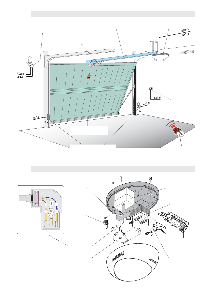
5.1 CONTROL BOARD DESCRIPTION
The board is powered by a power supply
socket (230V AC) and is protected in input
by a 1.6A mains fuse. The control devices
are low-voltage and protected by a 3.15A
fuse. The overall rated power of the 24V
accessories, protected by 3.15A fuse, must
not exceed 40W.
Work time set at 80 seconds.
Commands
- Total stop, pushbutton connected to
the ST-G terminals, stop of the overhead
door with exclusion of the automatic
closing cycle; to resume movement, the
pushbuttons or radio-controls must be
used;
- Opening-closing, pushbutton connected
to G-Ps or by radio-control, see page 14,
function selections;
Safety
- Re-opening during closure, see function
selections;
- Photoelectric cell test. Function selections
dip switch 9 ON;
- Amperometric device : see NOTE.
Other functions
- Automatic closure, see function
selections;
- Obstacle detection , see function
selections;
- Pre-flashing, see function selections;
Connected accessories
- Courtesy light (24V-25W). Lamp that lights
up the manoeuvre zone after an opening
command; it remains on for a set time of 2
mins. 30 secs.
Optional accessories
- 2acourtesy light (24V-25W), connected to
the 20-K3 terminals.
-Flashing light indicating movement
(24V-25W max.), connected to the 20-K1
terminals;
- Board for supplying power by battery
that, in the event of blackout, intervenes
automatically. When mains comes back on,
it recharges the batteries;
- Radiofrequency board for remote control.
Adjiustments
- Adjustment of automatic closing time;
- Adjustment of amperometric sensitivity.
Important: after supplying electricity to
the system, the 1st manoeuvre is always
an opening one. During this phase, it is not
possible to close the door, but it is possible
to close it again after the complete opening
manoeuvre.
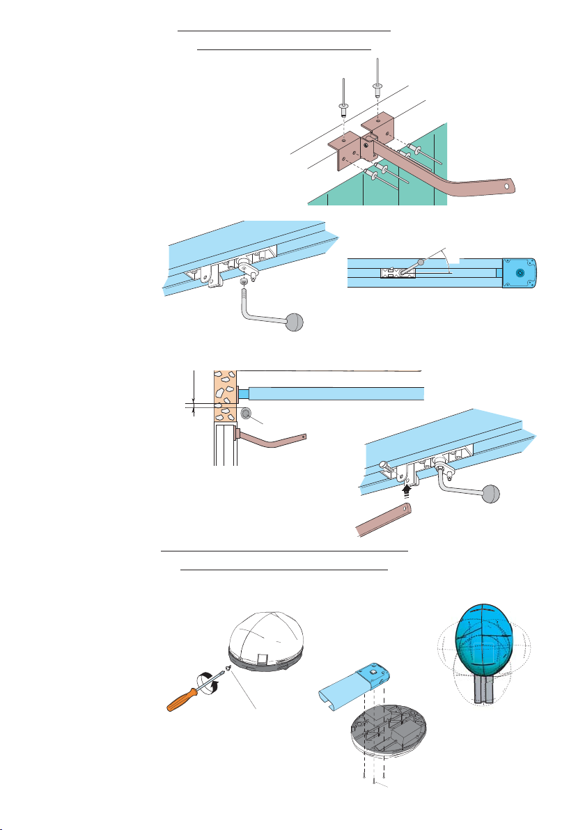
Important! Shut off the mains power
before servicing the inside of the unit.
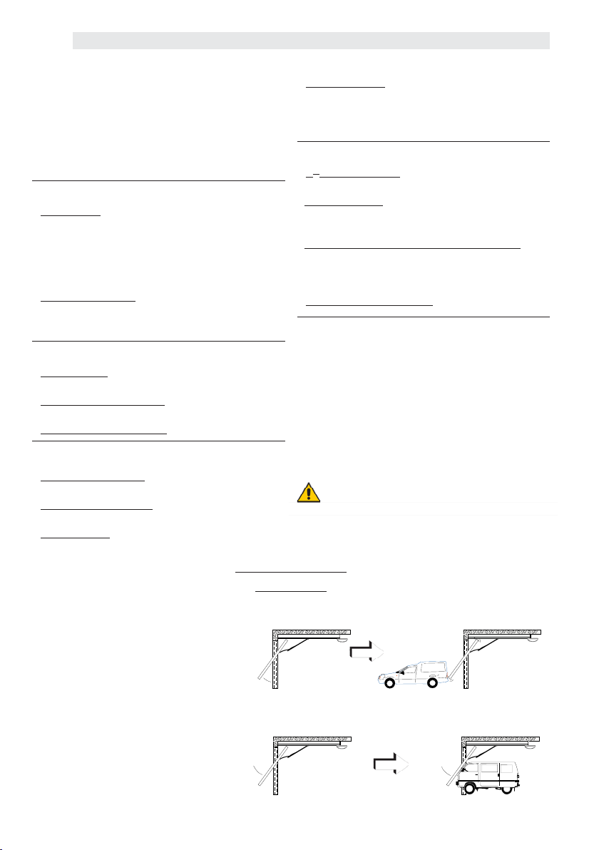
N.B.: In situation (b), if an obstacle is
detected three times, the door wing
stops during aperture, and auto-
matic closure is disactivated.
Use the keyboard or the radio trans-
mitter to resume movement of the
bar.
In the presence of an obstacle, the
amperometric device:
a) completely stops the door during
opening and subsequently closes it
automatically (if activated);
b) if in the closure phase, the move-
ment of the door is reversed.
NOTE

+
E
-
MN
3,15A
2
1 345678910
ON
OP / CH1
26V 17V 0V
315mA
8A
+
E
-
M N
CLOSE PS
20 21 ST G G Ps Tx T
20 K1 K3 20 G Tx D1 CNC
motostar
ENCODER SENS.
AUTOM.CLOSING.
XT100
ALIM PROG D1 ST
3,15A
2
1 345678910
ON
OP / CH1
26V 17V 0V
315mA
8A
+
E
-
MN
CLOSE PS
20 21 ST G G Ps Tx T
20 K1 K3 20 G Tx D1 CNC
motostar
ENCODER SENS.
AUTOM.CLOSING.
XT100
ALIM PROG D1 ST
26V 17V 0V
OP / CH1 CLOSE PS
ALIM PROG D1 ST
0V
230V
0
17
26
ST - G
Pag.
11
11 - Manual code:
119E7051GB
119E7051G B ver.
4
4 08/2013 - The data and information in this manual are subject to change at any time.
Blue
5.3 ELECTRICAL CONNECTIONS
Red
White
Green
Red
Transformer
Motor (24V d.c.) with En-
coder
Blue
Brown
White
5.2 CONTROL LED FUNCTIONS
GREEN LED «ALIM»
Signals that the
control board is
powered
RED LED «PROG»
With slow intermittent
flashing, signals that
the radio code has
been stored.
With rapid
intermittence and D1/
ST LED on, it signals
the presence of an
obstacle and/or the
malfunctioning of the
photoelectric cells
and stop button.
YELLOW LED «D1»
Signals the pres-
ence of an obstacle
between the safety
photoelectric cells.
YELLOW LED «ST»
Comes on every
time the “total
stop” button is
pressed.
Motor
Encoder

2
13456
ON
20 21 ST G GPs Tx T
20 K1 K3 20 G Tx D1 CNC
motostar
ENCODER SENS.
AUTOM.CLOSING.
XT100
+ 24V -
20 G Tx D1
Tx T
+ 24V -
G Ps
ST G
20 21
G Ps20 21 ST G 20 K1 K3 C NC
Pag.
12
12 - Manual code:
119E7051GB
119E7051G B ver.
4
4 08/2013 - The data and information in this manual are subject to change at any time.
N.B. All the contacts and push-buttons normally
closed (N.C.) which are not used must be disa-
bled by dip-switch or short-circuited.
CONNECTIONS FOR COMMAND ACCESSORIES
«Control» Pushbutton (N.O.), for the door
opening and closing (see dip-switch 2-3
function selections)
Incorporated reception antenna in the
flashing lamp for using the remote control
«Stop» Pushbutton (N.C.). Stops the over-
head door with the exclusion of the auto-
matic closing cycle. To resume the move-
ment, click the Control button.
Power supplies to other accessories (max
4W)- 24V (AC. - DC.)
RG58
Coaxial
cable

Tx T
20 G Tx D1 CNC Tx T 20 G Tx D1
Tx T
20 G Tx D1 CNC Tx T 20 G Tx D1
TX RX
20 K1
20 K3
TX
Tx T
20 G Tx D1 C NC
RX
Pag.
13
13 - Manual code:
119E7051GB
119E7051G B ver.
4
4 08/2013 - The data and information in this manual are subject to change at any time.
CONNECTIONS FOR SAFETY ACCESSORIES
Connection
with an pair of
photoelectric
cells during
re-opening
Connection with
an pair of pho-
toelectric cells
during re-opening
and possible
safety rib (re-
move the bridge
wire)
Connecting with a safety
rib by using only the C-NC
terminals (remove the
bridge wire and dip-switch
No. 7 in ON).
Flashing lamp (24V-25W). Flashes
during movements of the overhead
door with possibility of pre-flashing,
see function selections dip switch
4 ON.
Courtesy light (24V-25W). Lights up
the manoeuvre zone after an open-
ing command; remains on for a set
time of 2’ and 30”.

2
1345
ON
motostar
ENCODER SENS.
AUTOM. CLOSING.
XT100
2
1 345678910
ON
motostar
ENCODER SENS.
AUTOM. CLOSING.
XT100
ENCODER SENS.
m
ax. mi
n.
AUTOM. CLOSING
120" 1"
2
1 345678910
ON
Pag.
14
14 - Manual code:
119E7051GB
119E7051G B ver.
4
4 08/2013 - The data and information in this manual are subject to change at any time.
2
134
ON
1 ON Automatic closure activated;
the automatic closure timer self-
powers at the end stroke on ope-
ning. The adjustable pre-set time however
depends on whether any safety accessories
intervene and it is discontinued after a “stop”
or when no power is available;
2
134
ON
2 ON “Open-stop-close-stop” with
pushbutton (G-Ps) and radio-con-
trol (radio board inserted) activa-
ted;
2
134
ON
2 OFF “Open-close” with pushbut-
ton (G-Ps) and radio-control (radio
board inserted) activated;
2
1345
N
3 ON “Open only” with radio-control
(radio board inserted) activated;
5.4 FUNCTION SELECTIONS
5.5 ADJIUSTMENTS
23456
4 ON “Pre-flashing during opening/
closing activated; after an opening
or closing command, the flashing
lamp connected to 20-K1, flashes for 5
seconds before the manoeuvre begins;
45678
5 ON Obstacle detection with mo-
tor at limit switch activated; with
motor not running (door closed,
open or after a total stop command), stops
any movement if the safety devices (e.g.
photoelectric cells) detect an obstacle;
45678
6 Not used, keep the dip switch in
“OFF” position;
56789
7 OFF Re-opening during closure
activated; insert the safety device
(see photocells connection) if the
photoelectric cells detect an obstacle dur-
ing door closing, the movement direction re-
verses until the door is fully opened;
678910
8 ON End-stop programming ac-
tivated; enables the procedure for
adjusting the opening and closing
end runs;
8910
9 ON Photoelectric cells test ac-
tivated; upon every opening and
closing command of the overhead
door, the control unit checks the efficiency
of the photoelectric cells;
8910
10 Not used, keep the dip switch in
the «OFF» position;
Trimmer ENCODER SENS. =
Adjustment of amperometric
sensitivity.
Trimmer AUTOM. CLOSING. =
Automatic closure time adjust-
ment.
Select the functions by setting the dip
switch to ON or OFF using a screwdriver,
as indicated in the figure.
By default, Dip switch 7 is set to “ON”.

2
1 345678910
ON
motostar
2
1 345678910
ON
OP / CH1 CLOSE PS
motostar
ENCODER SENS.
AUTOM.CLOSING.
XT100
ALIM PROG D1 ST
8 ON
8 OFF
ON
OP / CH1 CLOSE PS
motostar
ALIM PROG D1 ST
ON
OP / CH1 CLOSE PS
motostar
ALIM PROG D1 ST
2
1 345678910
ON
OP / CH1 CLOSE PS
motostar
ENCODER SENS.
AUTOM.CLOSING.
XT100
ALIM PROG D1 ST
2
1 345678910
ON
OP / CH1 CLOSE PS
motostar
ALIM PROG D1 ST
Pag.
15
15 - Manual code:
119E7051GB
119E7051G B ver.
4
4 08/2013 - The data and information in this manual are subject to change at any time.
5.6 ENCODER PROGRAMMING
Closure limit switch
Set dip-switch 8 to ON: the
signalling LED flashes.
Press the “CLOSE” button and allow
the overhead door to reach the limit
switch when it closes.
Press the “PS” button: the signalling
LED remains on to indicate that the
closing end-stop has been saved.
Opening limit switch
Press the “OP/CH1” button and
allow the door to open fully.
Press the “PS” button: the signalling
LED remains on to indicate that the
opening limit switch has been saved
(see Note 1).
Return dip-switch 8 to OFF (see
Note 2).
IMPORTANT: READ THE INSTRUCTIONS CAREFULLY BEFORE PERFORMING PROGRAMMING.
Note 1
If you press the “OP/CH1” button
twice again within 15”, you will
disable the opening and closing
slow-downs; after pressing it for the
2nd time, the LED will start to flash
again.
Note 2
If after the repositioning dip switch 8
the LED begins to flash rapidly, you
will have to repeat the procedure
from the beginning.
General notes
During programming make sure you have first saved
the closing limit switch, otherwise the data will not be
saved.
Should the encoder malfunction or not be correctly
connected, when the opening or closing command is
given, the motor moves for a short section, after which
it stops, to signal the anomaly with a continuous slow
LED flashing. In this case, you must turn off the power
to the board and turn it on again.
SLIDING BLOCK
MECHANICAL
END-STOP
Mechanical END-STOP
With the door open, position the limit
switch in the transmission guide on
the sliding runner and secure it with
the screws.

CAME CANCELLI AUTOMATICI S.p.A.
Via Martiri Della Liberta’, 15
31030 Dosson di Casier - Treviso - Italia
Tel. +39 0422 4940 - Fax +39 0422 4941
www.came.com
www.came.com
OP / CH1 CLOSE PS
motostar
ENCODER SENS.
AUTOM.CLOSING.
XT100
ALIM PROG D1 ST
1
1
2
2
3
3
These instruction illustrate and describe
one or more typical installations.
For specific applications, which are not
mentioned herein, our technicians are
available to advise you.
Manual code:
119E7051GB
119E7051G B ver.
4
4 08/2013 - The data and information in this manual are subject to change at any time.
The unit requires no specific maintenance as such but we recommend that periodically the
moving parts (wheels etc.) and the door-arm pins are lubricated and that the chain’s tension is
checked and adjusted as necessary.
7.0 PERIODIC MAINTENANCE
6.0 PROGRAMMING THE RADIO CODE
If replacing the control board or the radio card,
you need to memorise the radio codes again, as
explained below.
Inserting the radio card
You MUST insert it when the main power is off,
because the control board will recognise it only
when the it is powered up.
Duplicating transmitters
Clickstar is already coded. To add transmitter to
those already supplied, follow this duplication
procedure:
1 - press the first two button simultaneously
until the LED flashes quicker;
2 - now press the button to be activated (the
LED will come ON);
3 - within 10 seconds, rest the active transmitter
against its back part and press down on the
button to be duplicated.
After saving, the LED will flash 3 times and tran-
smitter will be ready to use.
If necessary, repeat steps 1, 2 and 3 for the other
buttons.
Transmitter to be duplicated
Transmitter to
be added
Control board
Radio card
PROG led On
PROG led
Flashing
Memorising the code
Keep the “CH1” button pressed on the control
board: the signalling led starts flashing, ...
... now, with a transmitter button send the radio
code: the LED will stay on to indicate the code has
been memorised.
Table of contents
Other Motostar Garage Door Opener manuals
Popular Garage Door Opener manuals by other brands

Raynor
Raynor 3265RGDM 1/2 HP owner's manual

Nice
Nice TN2020LR10 Instructions and warnings for installation and use

Genie
Genie GCL-MT Product guide

Chamberlain
Chamberlain PowerDrive PD210 user manual

Telcoma Automations
Telcoma Automations ACE401 Operation and Programming Instructions

OpenGarage
OpenGarage OpenGarage Getting started guide