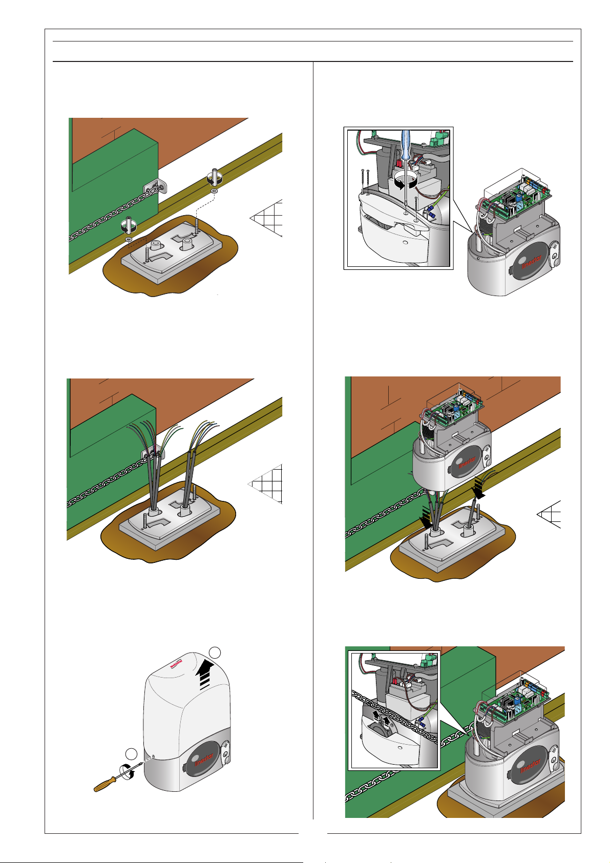
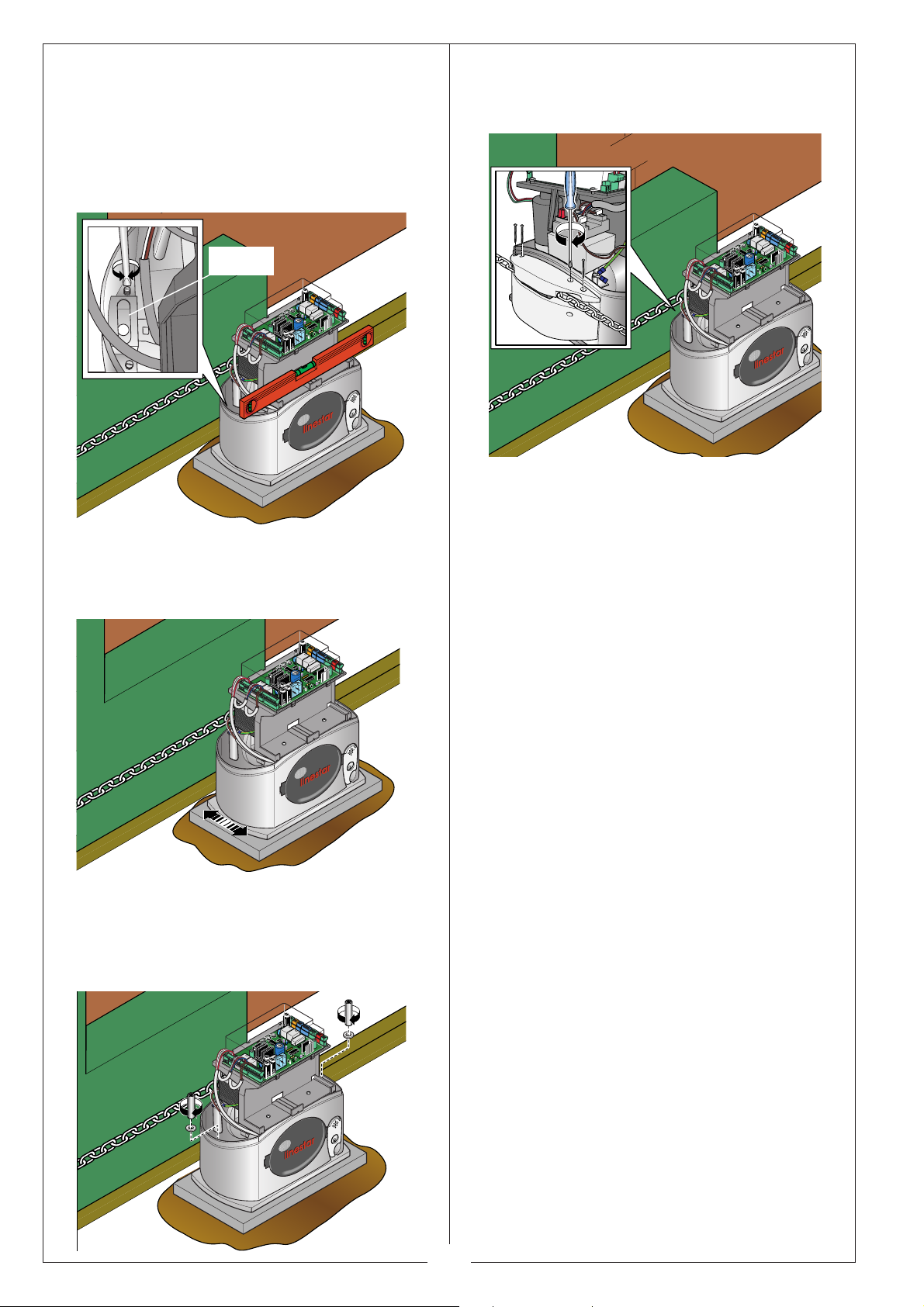
Motostar LINESTAR User manual

AUTAUT
AUTAUT
AUTOMAOMA
OMAOMA
OMATION FOR SLIDING GATION FOR SLIDING GA
TION FOR SLIDING GATION FOR SLIDING GA
TION FOR SLIDING GATESTES
TESTES
TES
INSTALLATION MANUAL
LINESTLINEST
LINESTLINEST
LINESTARAR
ARAR
AR

2
CONTENTS
1.0 Description of the system parts page 3
1.1 Description of the parties of the group gearmotor page 3
2.0 General characteristics page 4
2.1 Technical characteristics of the gearmotor page 4
2.2 Dimensions of the automation page 4
3.0 Unit assembly page 5
4.0 Description of the control board page 12
4.1 Main components of the control board page 13
4.2 Electric connections page 14
4.3 Check test for photoelectric cells operation page 19
4.4 Radio code programming pag. 19
4.5 Function selections pag. 20
4.6 Adjustments pag. 22
4.7 LED control functions pag. 23
4.8 Connection for the emergency batteries pag. 24
5.0 Maintenance pag. 24

3
400Kg max.
1
2
3
4
5
6
2
1.0 STANDARD SYSTEM DESCRIPTION
1.1 DESCRIPTION OFTHE GEARMOTOR UNIT COMPONENTS
1) Flashing lamp with
incorporated reception
antenna
2) Photoelectric cell
3) Gearmotor
4) Raceway for the electric
cables
5) Chain
6) Transmitter
1234567891011120203040506V1V2V3V4V5
57ND24-W
0043A
MALASYA
57ND24-W
0043A
MALASYA
57ND24-W
0043A
MALASYA
57ND24-W
0043A
MALASYA
57ND24-W
7WO.022uJ
0043A
MALASYA
Gearmotor
Transformer
Control
board
Cover
Chain fixing
brackets
Fixing plate
Chain-securing
hooks
Bracket fixing
screws
Gearmotor screws,
washers and locking
nuts
Place for emergency
batteries (not included)
Chain, DIN 766 G30
Type Aø5 L=4m
Extension bracket
Number of wires per cable
section:
- power supply: 3 x 1.5;
- photo-electric cell RX: 4 x 0.5;
- photo-electric cell TX: 2 x 0.5;
- flashing lamp: 2 x 1.5;
- antenna: RG58.

4
2.1 TECHNICAL CHARACTERISTICS OFTHE GEARMOTOR
2.0 GENERAL CHARACTERISTICS
2.2 DIMENSIONS OFTHE AUTOMATION
12 3 4 5 67891011120203 04 0506 V1
V2
V3
V4
V5
57ND24-W
0043A
MALASYA
57ND24-W
0043A
MALASYA
57ND24-W
0043A
MALASYA
57ND24-W
0043A
MALASYA
57ND24-W
7WO.022uJ
0043A
MALASYA
24V irreversible single-phase electromechanical gearmotor under power continues with
incorporated control panel powered at 230V AC.. Gearmotor casing in die-cast aluminium
inside which works an irreversible-reduction system with worm screw and helical crown.
Lubrication is by permanent grease fluid.
Power supply voltage: 230V AC - 50/60Hz
Max. absorbed power: 170W
Absorbed current: 7A max
Thrust: 300N
Max. velocity: 10 m/min
Max. use frequency: 48 cycles/h with 5 m gate.
Operative intermittence: 50%
Reduction ratio: 1/50
Operation environment temperature: from -20° to +70°C
Weight: 15 kg
210 mm 290 mm
160 mm
317 mm
104 mm
Automation for residential-use sliding gates with IP54 protection, equipped with:
- self-learning of the code between transmitter and radio receiver;
- adjustable end-stop unit in the automation;
- control board positioned horizontally in the upper part of the gearmotor to facilitate
electric cablings; completely insulated with protection cover;
- adjustable amperometric detector that, when encountering an obstacle, reverses the
movement of the wing during closure and stops it during opening;
- colored terminal boards to identify the various accessories and simplify the connections;
- Signalling LEDs: power present, programming and safety tests;
- Green LED that signals the power mains supply or red with emergency batteries inserted;
- emergency release with personalized wrench.

5
3.0 ASSEMBLY OF THE UNIT
Upper guide runners
Sliding wheels
Underground guide
Mechanical
End-stop
•Check that the
sliding wheels
are effi-
cient.
•The
underground guide
must be well
fixed to the ground, completely on the sur-
face along all its length and have no bends/
kinks to hinder gate movement.
•The
upper guide runners
must not cause
friction.
•Check the presence of an
mechanical
end-stop
during opening and closing, or
make provision for it.
INSPECTIONS OF THE GATE BEFORE INSTALLATION

6
400
300
240
40
PREPARING AND FIXING THE ANCHORING PLATE
•Prepare a cavity at a distance (see set-
tings) from the end of the gate. Prepare the
power sheath tubings and accessories in
the raceway, in the same way as for the
raceway and cavities.
TubingsCavity
Raceway
•Prepare a mold box that is larger than
the anchoring bracket and insert it into the
cavity.
•The mold box must emerge 50 mm above
ground level.
•Insert an iron grating to reinforce the ce-
ment and consolidate the anchoring
bracket.
Mold box
Griglia di ferro
•Prepare the anchoring bracket, insert the
screws to secure the unit, tightening them
with the nuts provided, as in the figure.
•Extract the plate’s pre-formed clamps with
a screwdriver or gripper as in the figure.
Nuts
Screws
Anchoring
bracket
a)
b)
c)
Iron grating
Washers
mm
m
m
50
m
Clambs

7
220 mm
55 mm
•Resting the fixing plate over the iron grat-
ing, being careful of the sheath tubings that
must pass through the holes already drilled
on the plate.
•Position the fixing plate at 55 and 220
mm from the gate when fully-open (see fig-
ure).
•Fill the mold box with cement. The plate
must be perfectly level, clean in all its ends,
with the screw threads fully on the surface.
•Wait for everything to solidify for at least
24 hours.
•Remove the box.
•Fill the cavity around the concrete block,
leaving the plate clean.
24h
55 mm

8
FIXING THE CHAIN
•On the gate, mark the distance of 110
mm between the anchoring base surface
and the bracket-securing holes.
•Make two 11 mm-diameter horizontal
holes with 30 mm between them.
•Insert the bushings into the holes and
secure the bracket with screws and wash-
ers.
•Secure the second bracket from the other
end of the gate, following the procedures
above.
•Secure the chain onto the bracket using
the tie rods, nuts, washers and the hooks
supplied.
•Secure the other end of the chain or, as
described above, cutting off any excess.
Pre-tension the chain with a 13 mm wrench
(Ref. 1).
N.B.:: should the gate not have a suitable
end (tail) to allow the gate to complete its
closing run, use the extension bracket (Ref.
2) supplied.
30mm
110 mm
Ref. 1Ref. 2

9
LAYING THE UNIT
•Insert the cables for the electrical con-
nections into the sheath tubings until they
extend about 400 mm from the tube.
•Remove the nuts and the washers from
the gearmotor fixing screws.
•Loosen the side screws and lift up the
cover.
1 2 3 4 5 6 7 8 9 1011120203040506V1V2V3V4V5
57ND24-W
0043A
MALASYA
57ND24-W
0043A
MALASYA
57ND24-W
0043A
MALASYA
57ND24-W
0043A
MALASYA
57ND24-W
7WO.022uJ
0043A
MALASYA
1
2
•Unscrew the pulley’s four upper-support
screws.
1234567891011120203040506V1V2V3V4V5
57ND24-W
0043A
MALASYA
57ND24-W
0043A
MALASYA
57ND24-W
0043A
MALASYA
57ND24-W
0043A
MALASYA
57ND24-W
7WO.022uJ
0043A
MALASYA
•Position the gearmotor over the anchor-
ing bracket with the screws in their slots
and insert the electric cables into the
gearmotor case unit.
1234567891
011120203040506V1V2V3V4V5
57ND24-W
0043A
MALASYA
57ND24-W
0043A
MALASYA
57ND24-W
0043A
MALASYA
57ND24-W
0043A
MALASYA
57ND24-W
7WO.022uJ
0043A
MALASYA
1234567891
011120203040506V1V2V3V4V5
57ND24-W
0043A
MALASYA
57ND24-W
0043A
MALASYA
57ND24-W
0043A
MALASYA
57ND24-W
0043A
MALASYA
57ND24-W
7WO.022uJ
0043A
MALASYA
•Align the gearmotor pulley with the chain
using the overall-adjustment system.

10
•The overall-adjustment system is made
up of:
- threaded steel feet allow for vertical ad-
justment and levelling;
1234567891
011120203040506V1V2V3V4V5
57ND24-W
0043A
MALASYA
57ND24-W
0043A
MALASYA
57ND24-W
0043A
MALASYA
57ND24-W
0043A
MALASYA
57ND24-W
7WO.022uJ
0043A
MALASYA
- slots, allow for horizontal adjustment.
1234567891
011120203040506V1V2V3V4V5
57ND24-W
0043A
MALASYA
57ND24-W
0043A
MALASYA
57ND24-W
0043A
MALASYA
57ND24-W
0043A
MALASYA
57ND24-W
7WO.022uJ
0043A
MALASYA
•Secure the gearmotor unit with the wash-
ers and nuts to make the unit hitch to the
plate in an integral manner.
1234567891
011120203040506V1V2V3V4V5
57ND24-W
0043A
MALASYA
57ND24-W
0043A
MALASYA
57ND24-W
0043A
MALASYA
57ND24-W
0043A
MALASYA
57ND24-W
7WO.022uJ
0043A
MALASYA
•Insert the pulley support and secure it.
1234567891011120203040506V1V2V3V4V5
57ND24-W
0043A
MALASYA
57ND24-W
0043A
MALASYA
57ND24-W
0043A
MALASYA
57ND24-W
0043A
MALASYA
57ND24-W
7WO.022uJ
0043A
MALASYA
Feet

11
RELEASING THE GEARMOTOR AND ADJUSTING THE END-STOP UNIT
•Insert the key, turn clockwise and lift the
door for release the gearmotor.
4
567891
011120203040506V1V2V3V4V5
57ND24-W
0043A
MALASYA
57ND24-W
0043A
MALASYA
57ND24-W
0043A
MALASYA
57ND24-W
0043A
MALASYA
57ND24-W
7WO.022uJ
0043A
MALASYA
•Use a screwdriver to remove the end-
stop unit cover.
1234567891
011120203040506V1V2V3V4V5
57ND24-W
0043A
MALASYA
57ND24-W
0043A
MALASYA
57ND24-W
0043A
MALASYA
57ND24-W
0043A
MALASYA
57ND24-W
7WO.022uJ
0043A
MALASYA
Cover
•Move the white cam anticlockwise until
the opening microswitch switches and
tighten it.
•Position the gate at 50 mm from full open-
ing.
•Move the red cam clockwise until the clo-
sure microswitch switches, and tighten it.
•Position the gate at 50 mm from the fully
closed position.
White cam
Red cam
50 mm
50 mm

12
4.0 DESCRIPTION OFTHE CONTROL BOARD
Caution! Shut off the mains power
and disconnect the batteries before
servicing the inside of the unit.
The control board is powered at 230V
(AC.) in the L-N terminals and is protected
in input with a 1A mains fuse. The control
devices are low-voltage type, and pro-
tected with a 3.15mA fuse.The overall rated
power of the 24V accessories, protected
with a 1.6A fuse, must not exceed 37W.
Control and safety logic
The control unit has an amperometric
device. It allows constant checking of the
motor force, which can be adjusted through
the
Trimmer Sensibility,
see adjustments.
When an obstacle is encountered, the
amperometric device causes the following
events:
a) the gate to stop during opening, with
subsequent automatic closing (if enabled);
b) reversal of the movement direction if
closing.
Caution: in case b, after the obstacle is
detected 3 times consecutively, the gate is
stopped at open position and the automatic
closing is excluded; to resume the
movement, you must press the command
pushbutton or use the remote-control.
The board has these functions:
-
opening-closure command
, button
connected to G-Ps or by radio-control, gate
opening and closing, see dip switches 2
and 3 (function selections);
-
partial opening command
, pushbutton
connected to G-Pp, opening for pedestrian
passage, see adjustments;
-
total stop,
pushbutton connected to the
ST-G terminals, gate stop with exclusion of
the automatic closing cycle;
-
“maintained action”
function, see dip
switch 6 (function selections);
-
pre-flashing,
see dip switch 4 (function
selections);
-
automatic closing,
see dip switch 1
(function selections) and adjustments;
-
obstacle detection
, see dip switch 5
(function selections);
-
photoelectric cells check test
, see dip
switch 10 (function selections).
The photoelectric cells may be pre-set to:
-
re-open
during closure, see dip switch 7
(function selections);
-
partial stop
, see dip switch 8 (function
selections).
The board includes trimmers for adjusting:
- partial opening;
- automatic closing time;
- amperometric sensitivity.

13
1234567891011120203040506V1
V2
V3
V4
V5
57ND24-W
0043A
MALASYA
57ND24-W
0043A
MALASYA
57ND24-W
0043A
MALASYA
57ND24-W
0043A
MALASYA
57ND24-W
7WO.022uJ
0043A
MALASYA
4.1 MAIN COMPONENTS OFTHE CONTROL BOARD
1- Terminal board for connecting the 230V (AC.) power supply
2 - Terminal boards for connecting the transformer
3 - Terminal board for connecting signalling accessories
4- Terminal board for connecting the end-stop unit
5 - Terminal board for connecting the RG58 cable for the antenna
6 - Radiofrequency board for remote control
7 - Trimmer for adjusting partial opening
8 - Pushbutton for memorizing the radio code
9 - Terminal boards for connecting the safety ribs
10 - Terminal boards for connecting the photoelectric cells in partial stop position
11 - Motor fuse 7.5A
12 - Terminal boards for connecting the photoelectric cells during re-opening
13 - Terminal board for connecting the motor
14 - Terminal board for connecting possible accessories
15 - Terminal board for connecting the “voltage presence” notifying LED
16 - Terminal board for connecting the command buttons
17 - Terminal board for connecting the stop button
18 - Terminal board for connecting the emergency batteries
19 - Functions control LED
20 - Trimmer for obstacle-detection sensitivity adjustment
21 - “Dip-switch” - Functions selector
22 - Trimmer for automatic closing-time adjustment
23 - Control unit fuse 630mA
24 - Accessories fuse 1.6A
25 - Line fuse 1A
+
0
M
N
20
21
20
Pp
SENSIBILIT
Y
P
ART.
O
PE
N
CH1
PRO
G
R
.
2
1345678910
ON
315mA
1
A
1,6A
7.5A
XS10
0
PROG D1 D3
ST
ALIM
L1T
N
D
EXTERNAL LED
D
T
X1
T
20
G
T
X1
D
3
G
D
7
G
D
6
S
W1 = A
uto
m
at
i
c
c
l
osu
r
e
SW2 = O
p
en/Close/Revers
e
SW3 = Open onl
y
SW4 = Preflashin
g
S
W
5
=
Obstac
le
d
e
t
e
ct
i
on
SW7 = Reopenin
g
durin
g
closin
g
SW8 = Partial sto
p
SW9 = Function slowin
g
activate
d
SW10 = Safet
y
test function
SW6 = Manual o
p
eratio
n
DIP
S
WIT
C
H F
U
N
C
TI
ON
D6
D7
2
1
109
3
13
2124 2325 19
612
4
5
7
14
15
16
17
18
11
2022
8

14
1234567891
011120203040506V1V2V3V4V5
57ND24-W
0043A
MALASYA
57ND24-W
0043A
MALASYA
57ND24-W
0043A
MALASYA
57ND24-
W
0043A
MALASYA
57ND24-W
7WO.022uJ
0043A
MALASYA
4.2 ELECTRIC CONNECTIONS
GEARMOTOR, TRANSFORMAR, POWER SUPPLY AND LIMIT SWITCH
Power supply 230V
(a.c.) - 50/60Hz
Motor
(24V d.c.)
Orange
Viola
Blu
Black
White
Red
Green
26
26
17
17
0
0
+
0 0 0 0 0 1
0 0 0 0 0 1
Ref.Des.
Ref.Des.
00000
00000
1 2 3 4 5 6 7 8
1 2 3 4 5 6 7 8
00000
1 2
00000
1 2
26 17 0
FA
FA
FC
FC
F
F
FA FC F
FA FC F
L2T L1T
FA
FA
FC
FC
F
F
FA FC F
FA FC F
LN
TX T
20 GTX NM
NM
FA
FA
FC
FC
F
F
FA FC F
FA FC F
FA
FC F
Limit switch group
If assembly has to be on the left, invert the end-stop FA-FC electric wire and M-N motor
phases.
Rosso
Verde
Motor
(24V d.c.)
Orange
White
Red
Orange
White
Red
N
L
Limit switch group
26 17 0
+
0 0 0 0 0 1Ref.Des.
00000
1 2 3 4 5 6 7 8
FA
FC F
FA FC F
FAFC F
FA FC F
TX T
20 GTX NM
NM
NM
FA
FC F
FA FC F
+ BATT -
26 17 0
+
0 0 0 0 0 1Ref.Des.
00000
1 2 3 4 5 6 7 8
FA
FC F
FA FC F
FAFC F
FA FC F
TX T
20 GTX NM
NM
FA
FA
FC
FC
F
F
FA FC F
FA FC F
FA
FC F
26 17 0
+
0 0 0 0 0 1Ref.Des.
00000
1 2 3 4 5 6 7 8
FA
FC F
FA FC F
FAFC F
FA FC F
TX T
20 GTX NM
NM
NM
FA
FC F
FA FC F
0
230
0
17
26
Transformer

15
SIGNALLING AND LIGHTING DEVICES
K5K5 K1K1 2020 FC
+
K5 K1 20
1 2
TX T
20 GTX NM
NM
K5 K1 20 FC
+
1 2
EXTERNAL LED
TX T
20 GTX NM
NM
Voltage signalling LED.
It signals voltage in the electric panel.
Green LED
indicates that
the panel is powered by
mains voltage
.
Red LED indicates that
the panel is powered with
emergency batteries.
Black
Red
Blue
Flashing lamp (24V-25W), signals,
with the intermittent flashing, the gate
movement with possibility of pre-
flashing while opening and closing
(see function selections dip switch 4
ON) or cycle lamp (24V-25W). It
remains on during the opening and
closing manoeuvre (with automatic
closing and detection of obstacle
functions enabled, dip switch Nos. 1
and 5 ON).
Lamp pilot light (24V-3W),
remains on to indicate
«gate open».

16
COMMAND DEVICES
Incorporated
reception antenna
for remote radio-
control use.
Additional
accessories
power supply
24V (AC. -
DC.), max
40W.
Caution: all the contacts and push-buttons normally closed (N.C.) not used, must be
disabled by dip-switch or short-circuited.
Pedestrian opening pushbutton
N.O. contact, partial opening of the
gate for pedestrian passage or
opening in maintained action,
gate opening keeping pressed the
pushbutton (dip switch 6 in ON).
GPs
G
ST
+
21
20
1 2
1
TX T
GTX NM
NM
G
G
Ps
Ps
G
G
ST
ST
+
21
21
20
20
20
+21
-
GPs Pp
1 2
1 2
ST G
TX T
GTX NM
NM
«Stop» pushbutton
N.C. contact(
remove
the bridge wire
). It stops
the gate with the
exclusion of the
automatic closing cycle.
To resume movement,
use the control button
or remote control.
Pushbutton for «Commands» con-
tact N.O., for gate opening and clos-
ing (see dip switch 2) or closing in
operation with maintained action,
gate closure keeping constantly
pressed the pushbutton (dip switch
6 ON).
Pedestrian passage Manteined action
opening
For commands Maintained action
closure

17
SAFETY DEVICES
TX T
20
20
G
G
TX
TX
20 G Tx D1
Connecting of a pair of photoelectric cells in re-opening during the gate-closure phase
(dip switch 7 OFF and 8 ON).
TX
RX
26 17 0K5 K1 20 FA
FC F
GPs
G
ST
-+
+
FA FC F
0 0 0 0 0 1Ref.Des.
00000
1 2 3 4 5 6 7 8
21
20
Tx
T
20
G
Tx
D1
1 2
AUTOM.CLOSIN
G
SEN
S
IBILIT
Y
PA R T.
O
PE
N
G
R
.
7.5A
FA
FC F
FA FC F
FA
FC F
FA FC F
T
X1
T
20
D
3
G
D
7
G
D
6
26 17 0K5 K1 20 FA
FC F
GPs
G
ST
-+
+
FA FC F
0 0 0 0 0 1Ref.Des.
00000
1 2 3 4 5 6 7 8
21
20
Tx
T
20
G
Tx
D1
1 2
AUTOM.CLOSIN
G
SEN
S
IBILIT
Y
PA R T.
O
PE
N
G
R
.
7.5A
FA
FC F
FA FC F
FA
FC F
FA FC F
T
X1
T
20
D
3
G
D
7
G
D
6
Connection of a pair of photoelectric cells in re-opening during the closure phase and one
in partial stop (dip switches 7 and 8 OFF).
Photoelectric cells in partial stop
Photoelectric cells in re-opening
TX
TX
T
T
Tx T
20 GTX
TX
RX
TX
TX
T
T
Tx T
20 GTX
TX T
20
20
G
G
TX
TX
20 G Tx D1
TX
RX
TX
TX
T
T
Tx T
20 GTX

18
Connecting a pair of photoelectric cells in re-opening and in partial stop, with possible
connecting of a safety rib in reopening during gate closure and one in re-closing during
opening.
26 17 0K5 K1 20 FA
FC F
GPs
G
ST
-+
+
FA FC F
0 0 0 0 0 1Ref.Des.
00000
1 2 3 4 5 6 7 8
21
20
Tx
T
20
G
Tx
D1
1 2
AUTOM.CLOSIN
G
SEN
S
IBILIT
Y
PA R T.
O
PE
N
OG
R
.
7.5A
FA
FC F
FA FC F
FA
FC F
FA FC F
T
X1
T
20
D
3
G
D
7
G
D
6
Photoelectric cells in partial stop
Photoelectric cells in re-opening
Safety rib in re-closing,
N.C. contact. (remove the
bridge wire)
Safety rib in re-opening,
N.C. contact. (remove the
bridge wire)
RX
TX
TX T
20
20
G
G
TX
TX
20 G Tx D1
TX
RX
TX
TX
T
T
Tx T
20 GTX
TX
RX
TX
TX
T
T
Tx T
20 GTX

19
4.3 CHECKTEST OF THE PHOTOELECTRIC CELLS OPERATION
Tx
T
20
G
Tx
D1
AUTOM.CLOSIN
G
SEN
S
IBILIT
Y
PA R T.
O
PE
N
OG
R
.
7.5A
T
X1
T
20
G
T
X1
D
3
G
D
7
G
D
6
TX T
20 G TX D1
4.4 RADIO CODE PROGRAMMING
TX T
20 G TX D1
DIP «10» activation of the
test function
Allows the control unit to check
the efficiency of the safety
devices (photoelectric cells) at
every opening or closure
command.
To activate this function, move
dip switch 10 to ON (see page
23 for the LED signallings).
Radiofrequency board insertion
The radiofrequency board should ALWAYS be
inserted when the power is off because the
motherboard only ecognises it when it is
powered.
Code storage
Keep the “CH1/PROG” key pressed on the
base card (the signal LED will flash), and with
a key on the transmitter the code is sent, the
LED will remain lit to signal the successful
saving of the code.
If the motherboard is replaced or the
Radiofrequency board is reprogrammed,
perform the programming operation (memoriz-
ing) of the radio code again.
transmitters duplication
Clikstar is already coded. To add transmitters
to the ones supplied, follow the following
duplication procedure:
1) Press the button to code until after 7" of
flashing, the Red signalling LED comes on (1);
2) Within 10", place the transmitter to duplicate
on the rear part and for a few seconds press
the button to copy (2).
After memorizing, the LED will flash 3 times
and the transmitter will be ready for use.
If necessary, repeat 1 and 2 for the other
buttons (which can be used for other
automations).
2
1
Transmitter to add
Transmitter to duplicate
G
Ps
PROGD1D3
ST
ALIM
D6
D7
2
1345678910
ON
LED «D1 or D3» photoelectric
cells malfunction warning
Stop
parziale
Riapertura in fase di
chiusura
26 17 0K5 K1 20 FA
FC F
GPs
G
ST
-+
+
FA FC F
0 0 0 0 0 1Ref.Des.
00000
1 2 3 4 5 6 7 8
NM
21
20TX T
20 GTX
1 2
FA
FC F
FA FC F
FA
FC F
FA FC F
TX T
20 GTX NM
NM
26 17 0K5 K1 20 FA
FC F
GPs
G
ST
-+
+
FA FC F
0 0 0 0 0 1Ref.Des.
00000
1 2 3 4 5 6 7 8
NM
21
20TX T
20 GTX
1 2
CH1
PROGR.
910
PROGD1D3
ALIM
FA
FC F
FA FC F
FA
FC F
FA FC F
TX T
20 G TX NM
NM
D6
26 17 0K5 K1 20 FA
FC F
GPs
G
ST
-+
+
FA FC F
0 0 0 0 0 1Ref.Des.
00000
1 2 3 4 5 6 7 8
NM
21
20TXT
20 GTX
1 2
CH1
PROGR.
910
PROGD1D
ALIM
FA
FC F
FA FC F
FA
FC F
FA FC F
TX T
20 GTX NM
NM
D

20
4.5 FUNCTION SELECTIONS
+
0
M
N
20
21
20
Pp
SEN
S
IBILITY
PA RT.
O
PE
N
CH1
PRO
G
R
.
2
1345678910
ON
315mA
1
A
1,6A
7.5A
XS10
0
PROG D1 D3
ST
ALIM
L1T
N
D
EXTERNAL LED
D
T
X1
T
20
G
T
X1
D
3
G
D
7
G
D
6
S
W1 = A
uto
m
at
i
c
c
l
osu
r
e
SW2 = O
p
en/Close/Revers
e
SW3 = Open onl
y
SW4 = Preflashin
g
S
W
5
=
Obstac
le
d
e
t
e
ct
i
on
SW7 = Reopenin
g
durin
g
closin
g
SW8 = Partial sto
p
SW9 = Function slowin
g
activate
d
SW10 = Safet
y
test function
SW6 = Manual o
p
eratio
n
DIP
S
WIT
C
H F
U
N
C
TI
ON
D6
D7
Remove the board protection, removing
the two screws as shown in the figure.
1234567891
011120203040506V1V2V3V4V5
57ND24-W
0043A
MALASYA
57ND24-W
0043A
MALASYA
57ND24-W
0043A
MALASYA
57ND24-W
0043A
MALASYA
57ND24-W
7WO.022uJ
0043A
MALASYA
1 ON Automatic closure; the automatic-clo-
sure timer self-powers at the end of the
opening movement time. The adjustable
pre-set time however depends on the in-
tervention of any safety accessories and it
is cut out after a “stop” intervention or in
the event of a power failure;
2 ON - 3 OFF “Open-stop-close-stop” with
pushbutton (G-Ps) and remote control
(radio board inserted);
2 OFF - 3OFF “Open-close” with
pushbutton (G-Ps) and remote control
(radio board inserted);
3 ON “Open only” with remote control (ra-
dio board inserted);
4 ON “Pre-flashing during opening and
closing; after an opening or closing com-
mand, the flashing lamp connected to 20-
K1 flashes for 5 seconds before beginning
the manoeuvre;
+
2
1345678910
ON
Select the functions by setting the dip
switch to ON or OFF, using a screwdriver
as indicated in the figure.
By default, dip switches 7 and 8 are set to
“ON”.
12
6
39
1
2
4
57
8
10
11
1" 120"
Table of contents
Other Motostar Garage Door Opener manuals
Popular Garage Door Opener manuals by other brands

Smart Openers
Smart Openers SMART ROLLER DUO installation manual

Xceltronix
Xceltronix autoCLOSER Series Installation manual and user's guide

SkyLink
SkyLink GT-100A user manual

Chamberlain
Chamberlain Merlin MGS300 manual

Nice
Nice Pop Instructions and warnings for the fitter

Chamberlain
Chamberlain MotorLift ML500 manual

BFT
BFT SILENTE manual

Amourelle
Amourelle AP433RX2 installation instructions

Merlin
Merlin Tiltmaster MT100EVO Installation and operating instructions

V2
V2 ALFARISS manual

Gliderol
Gliderol Glidermatic GRD Installation instructions and owner's manual

Motorisation+
Motorisation+ SIMPLY Instructions and warnings for installation and use