Motrona CI800 User manual

Operating Manual
motrona GmbH, Zeppelinstraße 16, DE - 78244 Gottmadingen, Tel. +49 (0) 7731 9332-0, Fax +49 (0) 7731 9332-30, [email protected], www.motrona.com
CI800
CANopen Interface Module for MC800 Motion Controller
Product features:
CANopen Slave compliant to CiA DS301 V 4.02
Process data communication with 4 Receive-PDOs and 4 Transmit-PDOs
Galvanically isolated bus electronics
Supports all standard baud rates
Easy plug-in mounting

Ci800_01a_oi_e.doc / Jul-17 Page 2 / 18
Version:
Description:
Ci800_01a_oi_e / TJ / Jul 17
First edition
Legal notices:
All contents included in this manual are protected by the terms of use and copyrights of motrona GmbH. Any
reproduction, modification, usage or publication in other electronic and printed media as well as in the internet requires
prior written authorization by motrona GmbH.

Ci800_01a_oi_e.doc / Jul-17 Page 3 / 18
Table of contents
1. Safety Instructions and Responsibility ......................................................... 4
1.1 General Safety Instructions...................................................................................4
1.2 Use according to the intended purpose ................................................................4
1.3 Installation.............................................................................................................5
1.4 Cleaning, Maintenance and Service Notes...........................................................5
2. General........................................................................................................ 6
3. Connections and LEDs ................................................................................. 7
4. Mounting..................................................................................................... 8
5. Operation................................................................................................... 12
5.1 Parameter setting in the MC800 firmware .........................................................12
5.2 SDO communication............................................................................................13
5.3 PDO communication ............................................................................................13
5.4 Emergency Message ...........................................................................................14
5.5 Node Guarding ....................................................................................................14
5.6 EDS ......................................................................................................................14
6. Object Dictonary ........................................................................................ 15
6.1 CANopen Standard Objects (Communication Objects ........................................15
6.2 Manufacturer Specific Objects (MC800 firmware parameters)..........................16
7. Technical Data........................................................................................... 18

Ci800_01a_oi_e.doc / Jul-17 Page 4 / 18
1. Safety Instructions and Responsibility
1.1 General Safety Instructions
This operation manual is a significant component of the unit and includes important rules and
hints about the installation, function and usage. Non-observance can result in damage and/or
impairment of the functions to the unit or the machine or even in injury to persons using the
equipment!
Please read the following instructions carefully before operating the device and observe all
safety and warning instructions! Keep the manual for later use.
A pertinent qualification of the respective staff is a fundamental requirement in order to use
these manual. The unit must be installed, configured, commissioned and serviced by a qualified
electrician.
Liability exclusion: The manufacturer is not liable for personal injury and/or damage to property
and for consequential damage, due to incorrect handling, installation, operation and maintaining.
Further claims, due to errors in the operation manual as well as misinterpretations are excluded
from liability. In addition the manufacturer reserves the right to modify the hardware, software or
operation manual at any time and without prior notice. Therefore, there might be minor
differences between the unit and the descriptions in operation manual.
The raiser is exclusively responsible for the safety of the system and equipment where the unit
will be integrated.
During installation, operation or maintenance all general and also all country- and application-
specific safety rules and standards must be observed.
If the device is used in processes, where a failure or faulty operation could damage the system or
injure persons, appropriate precautions to avoid such consequences must be taken.
1.2 Use according to the intended purpose
The unit is intended exclusively for use in industrial machines, constructions and systems. Non-
conforming usage does not correspond to the provisions and lies within the sole responsibility of
the user. The manufacturer is not liable for damages which have arisen through unsuitable and
improper use.
Please note that device may only be installed in proper form and used in a technically perfect
condition in accordance to the “Technical Specifications”. The device is not suitable for operation
in explosion-proof areas or areas which are excluded by the EN 61010-1 standard.

Ci800_01a_oi_e.doc / Jul-17 Page 5 / 18
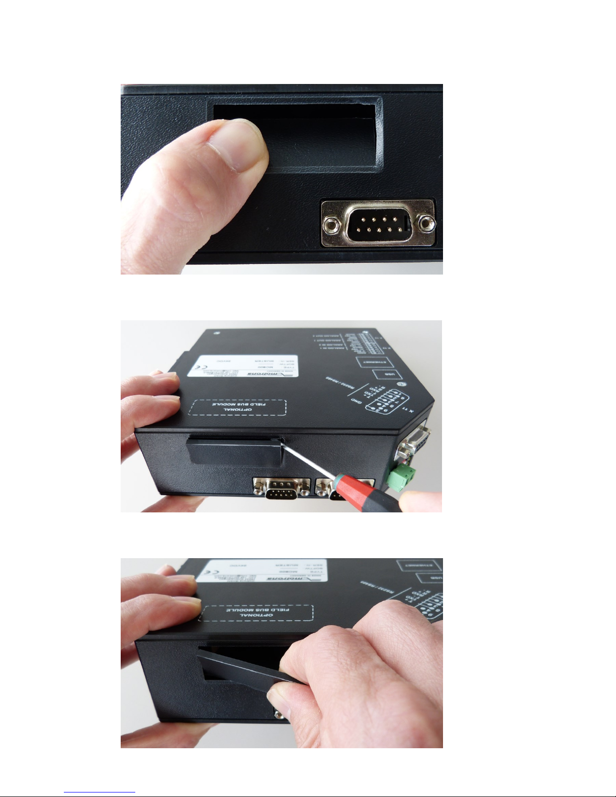
1.3 Installation
The device is only allowed to be installed and operated within the permissible temperature range.
Please ensure an adequate ventilation and avoid all direct contact between the device and hot or
aggressive gases and liquids.
Before installation or maintenance, the unit must be disconnected from all voltage-sources.
Further it must be ensured that no danger can arise by touching the disconnected voltage-
sources.
Devices which are supplied by AC voltages must be connected exclusively by switches,
respectively circuit-breakers with the low voltage network. The switch or circuit-breaker must be
placed as near as possible to the device and further indicated as separator.
Incoming as well as outgoing wires and wires for extra low voltages (ELV) must be separated
from dangerous electrical cables (SELV circuits) by using a double resp. increased isolation.
All selected wires and isolations must be compliant to the provided voltage- and temperature-
ranges. Further all country- and application-specific standards, which are relevant for structure,
form and quality of the wires, must be ensured. Indications about the permissible wire cross-
sections for wiring are described in the “Technical Specifications” chapter.
Before first start-up it must be ensured that all connections and wires are firmly seated and
secured in the screw terminals. All (inclusively unused) terminals must be fastened by turning the
relevant screws clockwise up to the stop.
Overvoltage at the connections must be limited to values in accordance to the overvoltage
category II.
For placement, wiring, environmental conditions as well as shielding and earthing/grounding of
the supply lines the general standards of industrial automation industry and the specific shielding
instructions of the manufacturer are valid. Please find all respective hints and rules on
www.motrona.com/download.html --> “[General EMC Rules for Wiring, Screening and Earthing]”.
1.4 Cleaning, Maintenance and Service Notes
To clean the front of the unit please use only a slightly damp (not wet!), soft cloth. For the rear no
cleaning is necessary. For an unscheduled, individual cleaning of the rear the maintenance staff
or assembler is self-responsible.
During normal operation no maintenance is necessary. In case of unexpected problems, failures
or malfunctions the device must be shipped for back to the manufacturer for checking, adjustment
and reparation (if necessary). Unauthorized opening and repairing can have negative effects or
failures to the protection-measures of the unit.

Ci800_01a_oi_e.doc / Jul-17 Page 6 / 18
2. General
The CI800 interface module provides instant CANopen connectivity of the MC800 universal
motion controller.
It is a standard CANopen Slave compliant to CiA DS301 V 4.02.
The CAN bus connection is galvanically isolated and supports all standard baud rates as well as
auto baudrate detection.
The interface module allows easy parameter access via SDO communication and process data
transfer with 4 Receive-PDOs and 4 Transmit-PDOs.
For the operation of the interface module and the understanding of this manual basic knowledge
in CANopen communication is presupposed.

Ci800_01a_oi_e.doc / Jul-17 Page 7 / 18
3. Connections and LEDs
Front view:
LED “RUN”: Indicates the actual CANopen state
LED state
Indication
Description
Off
No power
Green
Operational
The Module is in the CANopen state “Operational”
Green blinking
Pre-operational
The Module is in the CANopen state “Pre-Operational”
Green single flash
Stopped
The Module is in the CANopen state “Stopped”
Green flickering
Autobaud
Baud rate detection in progress
Red
Exception state
Fatal error
LED “ERR”: Indicates bus errors
LED state
Indication
Description
Off
No power or device is in working condition
Red single flash
Warning limit
reached
A bus error counter has reached or exceeded its warning
level
Red double flash
Error Control
Event
A guard event (NMT-Slave or NMT-Master) or heartbeat
event (Heartbeat consumer) has occurred
Red
Bus off
Bus off
CAN connector (D-Sub 9-pin male):
Pin
Signal
Comments
1, 4, 6, 8, 9
Unused
2
CAN_L
CAN_L bus line
3
CAN_GND
CAN ground
5
CAN_SHLD
CAN shield
7
CAN_H
CAN_H bus line
Housing
CAN_SHLD
CAN shield

Ci800_01a_oi_e.doc / Jul-17 Page 8 / 18
4. Mounting
If you want to mount the interface module for the very first time in your MC800 (cut-out at
housing still closed) please follow the steps below.
However, if the slot for the interface module is already available in your MC800’s housing, please
go on with step 6.
1. Press slightly with your thumbs to the housing as shown in the picture until you can see
the predetermined breaking edges of the cut-out

Ci800_01a_oi_e.doc / Jul-17 Page 9 / 18
2. Carefully press to the upper side of the predetermined cut-out until the edge breaks
3. Flap the cut-out piece to the exterior with a small screw driver.
4. Dismantle the cut-out piece

Ci800_01a_oi_e.doc / Jul-17 Page 10 / 18
5. The mounting slot for the interface module is now ready for use
6. Insert the interface module carefully.
Please make sure that the module properly fits to the sliding bars in the slot, otherwise
the connector pins can be damaged!

Ci800_01a_oi_e.doc / Jul-17 Page 11 / 18
7. Tighten the two locking screws with a TORX 8 screwdriver
8. If you remove the interface module and leave the mounting slot empty, please cover the
slot.
A suitable cover is available on request (motrona part no. 42160).

Ci800_01a_oi_e.doc / Jul-17 Page 12 / 18
5. Operation
5.1 Parameter setting in the MC800 firmware
In the MC800 firmware you will find the parameters for the interface module in parameter block
“Communication settings” on the right hand side of the according register card:
Fieldbus address
CANopen Node Address
Setting range 1…127
Fieldb. Baudrate
CAN transmission rate:
0: 10 kbps
1: 20 kbps
2: 50 kbps
3: 100 kbps
4: 125 kbps
5: 250 kbps
6: 500 kbps
7: 800 kbps
8: 1000 kbps
9: Auto (Automatic baud rate detection)
Fieldbus Mode
Not in use
Transmit Data 1
Mapping of the TPDO 1 (Transmit Process Data Object 1):
Register number of the MC800 parameter that is transmitted by TPDO 1.
See column “#” in MC800 firmware manual parameter tables for the required
number.
Example:
With Transmit Data 1 = 581 the Output Status is transmitted by TPDO 1
Please see below for details of the PDO communication.

Ci800_01a_oi_e.doc / Jul-17 Page 13 / 18
Transmit Data 2
As above, but for TPDO 2 (Transmit Process Data Object 2)
Transmit Data 3
As above, but for TPDO 3 (Transmit Process Data Object 3)
Transmit Data 4
As above, but for TPDO 4 (Transmit Process Data Object 4)
Receive Data 1
Mapping of the RPDO 1 (Receive Process Data Object 1):
Register number of the MC800 parameter that is received by TPDO 1.
See column “#” in MC800 firmware manual parameter tables for the required
number.
For unused PDOs please set the value to 0.
Example:
With Receive Data 1 = 579 the Bus Command Status (setting of commands via
fieldbus) is received by RPDO 1
Please see below for details of the PDO communication.
Receive Data 2
As above, but for RPDO 2 (Receive Process Data Object 2)
Receive Data 3
As above, but for RPDO 3 (Receive Process Data Object 3)
Receive Data 4
As above, but for RPDO 4 (Receive Process Data Object 4)
(Parameter 27…31)
Not in use
5.2 SDO communication
All parameters are accessible by SDO (Service Data Object) communication.
The Identifier for the SDOs are CANopen default:
Identifier of Receive SDO = 1536 (600 hex) + Node Address
Identifier of Transmit SDO = 1408 (580 hex) + Node Address
5.3 PDO communication
For fast process data exchange the interface module provides 4 Transmit PDOs (Process Data
Objects) and 4 Receive PDOs. The PDOs consist of 4 data byte and use the predefined CANopen
default identifiers. You can map one MC800 parameter to each PDO, therefore you can read up to
4 parameter values and write up to 4 parameter values by fast PDO transmission.
PDO
Identifier
Data Byte 0 … 3
Transmit PDO 1
180 hex + Node Address
Value of parameter defined in “Transmit Data 1”
Transmit PDO 2
280 hex + Node Address
Value of parameter defined in “Transmit Data 2”
Transmit PDO 3
380 hex + Node Address
Value of parameter defined in “Transmit Data 3”
Transmit PDO 4
480 hex + Node Address
Value of parameter defined in “Transmit Data 4”
Receive PDO 1
200 hex + Node Address
Value of parameter defined in “Receive Data 1”
Receive PDO 1
300 hex + Node Address
Value of parameter defined in “Receive Data 2”
Receive PDO 1
400 hex + Node Address
Value of parameter defined in “Receive Data 3”
Receive PDO 1
500 hex + Node Address
Value of parameter defined in “Receive Data 4”

Ci800_01a_oi_e.doc / Jul-17 Page 14 / 18
The PDO mapping can only be changed by MC800 parameters “Transmit Data 1” to “Receive Data
4”. Change of the mapping via CANopen is not supported, i. e. the corresponding CANopen
Objects (1600 … 1603 hex and 1A00 … 1A03 hex) are read only.
The default transmission type for the PDOs is asynchronous (event driven), i. e. the corresponding
Transmit PDO is sent whenever the value of the mapped MC800 parameter changes. Values
received by a Receive PDO are transferred immediately to the register of the mapped MC800
parameter. However, the transmission type of each PDO can be changed by the CANopen Master
in the corresponding CANopen Objects (1400 … 1403 hex and 1800 … 1803 hex) if required.
PDO transmission is only possible when the interface module is in the CANopen state
“Operational”. To start the PDO communication, the CANopen master device must send the NMT
(Network Management) message “Start Remote Node”.
5.4 Emergency Message
When an error occurs in the MC800 firmware and MC800 output “Error” is set, the interface
module transmits a CANopen EMCY Message (identifier 80 hex + Node Address) with the Error
Code “Generic Error”.
After all pending errors of the MC800 firmware have been cleared and MC800 output “Error” is
reset, an EMCY message with all data bytes set to 0 is sent.
5.5 Node Guarding
The interface module supports the standard CANopen node guarding function for supervision by
the CANopen master.
5.6 EDS
The corresponding CANopen EDS file (Electronic Data Sheet) “CI800.eds” is available for
download on the motrona homepage.

Ci800_01a_oi_e.doc / Jul-17 Page 15 / 18
6. Object Dictionary
6.1 CANopen Standard Objects (Communication Objects
Index
(hex)
Object
Type
Object Name
Data Type
Access*
Remarks
1000
VAR
Device Type
Unsigned32
RO
0000 0000 h (No profile)
1001
VAR
Error Register
Unsigned8
RO
1003
ARRAY
Pre-defined error field
Unsigned32
RO
1005
VAR
COB-ID Sync
Unsigned32
RW
Default: 0000 0080 h
1008
VAR
Manufacturer device name
Vis-String
Const
100A
VAR
Manufacturer softw. version
Vis-String
Const
100C
VAR
Guard time
Unsigned16
RW
100D
VAR
Life time factor
Unsigned8
RW
1010
ARRAY
Store parameters
Unsigned32
RW
For communication
parameters only
1011
ARRAY
Restore default parameters
Unsigned32
RW
1014
VAR
COB-ID EMCY
Unsigned32
RO
1015
VAR
Inhibit time EMCY
Unsigned16
RW
Default: 0000 h
1016
ARRAY
Consumer heartbeat time
Unsigned32
RW
1017
VAR
Producer heartbeat time
Unsigned16
RW
1018
RECORD
Identity object
Identity
RO
1400
RECORD
1. Receive PDO Parameter
PDO CommPar
RW
1401
RECORD
2. Receive PDO Parameter
PDO CommPar
RW
1402
RECORD
3. Receive PDO Parameter
PDO CommPar
RW
1403
RECORD
4. Receive PDO Parameter
PDO CommPar
RW
1600
RECORD
1. Receive PDO Mapping
PDO Mapping
RO
1601
RECORD
2. Receive PDO Mapping
PDO Mapping
RO
1602
RECORD
3. Receive PDO Mapping
PDO Mapping
RO
1603
RECORD
4. Receive PDO Mapping
PDO Mapping
RO
1800
RECORD
1. Transmit PDO Parameter
PDO CommPar
RW
1801
RECORD
2. Transmit PDO Parameter
PDO CommPar
RW
1802
RECORD
3. Transmit PDO Parameter
PDO CommPar
RW
1803
RECORD
4. Transmit PDO Parameter
PDO CommPar
RW
1A00
RECORD
1. Transmit PDO Mapping
PDO Mapping
RO
1A01
RECORD
2. Transmit PDO Mapping
PDO Mapping
RO
1A02
RECORD
3. Transmit PDO Mapping
PDO Mapping
RO
1A03
RECORD
4. Transmit PDO Mapping
PDO Mapping
RO
*) RO = Read only, RW = Read and write

Ci800_01a_oi_e.doc / Jul-17 Page 16 / 18
6.2 Manufacturer Specific Objects (MC800 firmware parameters)
Index = 2000 hex + MC800 register number (marked with “#” in MC800 parameter tables)
Object name (= Parameter name) is firmware specific, please refer to corresponding MC800
firmware manual parameter tables
Index
(hex)
Object Name
MC800
Register #
(dec.)
Data Type
Access
Remarks
2001
General Parameter 00
1
Integer32
RW
…
…
…
…
…
2020
General Parameter 31
32
Integer32
RW
2021
Block01 Parameter 00
33
Integer32
RW
…
…
…
…
…
2040
Block01 Parameter 31
64
Integer32
RW
2041
Block02 Parameter 00
65
Integer32
RW
…
…
…
…
…
2060
Block02 Parameter 31
96
Integer32
RW
2061
Block03 Parameter 00
97
Integer32
RW
…
…
…
…
…
2080
Block03 Parameter 31
128
Integer32
RW
2081
Block04 Parameter 00
129
Integer32
RW
…
…
…
…
…
20A0
Block04 Parameter 31
160
Integer32
RW
20A1
Block05 Parameter 00
161
Integer32
RW
…
…
…
…
…
20C0
Block05 Parameter 31
192
Integer32
RW
20C1
Block06 Parameter 00
193
Integer32
RW
…
…
…
…
…
20E0
Block06 Parameter 31
224
Integer32
RW
20E1
Block07 Parameter 00
225
Integer32
RW
…
…
…
…
…
2100
Block07 Parameter 31
256
Integer32
RW
2101
Block08 Parameter 00
257
Integer32
RW
…
…
…
…
…
2120
Block08 Parameter 31
288
Integer32
RW
2121
Block09 Parameter 00
289
Integer32
RW
…
…
…
…
…
2140
Block09 Parameter 31
320
Integer32
RW

Ci800_01a_oi_e.doc / Jul-17 Page 17 / 18
Index
(hex)
Object Name
MC800
Register #
(dec.)
Data type
Access
Remarks
2141
Block10 Parameter 00
321
Integer32
RW
…
…
…
…
…
2160
Block10 Parameter 31
352
Integer32
RW
2161
Block11 Parameter 00
353
Integer32
RW
…
…
…
…
…
2180
Block11 Parameter 31
384
Integer32
RW
2181
Block12 Parameter 00
385
Integer32
RW
…
…
…
…
…
21A0
Block12 Parameter 31
416
Integer32
RW
21A1
Counter Settings Par. 00
417
Integer32
RW
…
…
…
…
…
21C0
Counter Settings Par. 31
448
Integer32
RW
21C1
Encoder Settings Par. 00
449
Integer32
RW
…
…
…
…
…
21E0
Encoder Settings Par. 31
480
Integer32
RW
21E1
Communication Par. 00
481
Integer32
RW
…
…
…
…
…
2200
Communication Par. 31
512
Integer32
RW
2201
Set-up Settings Par. 00
513
Integer32
RW
…
…
…
…
…
2220
Set-up Settings Par. 31
544
Integer32
RW
2221
Actual Value 00
545
Integer32
RO
…
…
…
…
…
2240
Actual Value 31
576
Integer32
RO
2241
Status of Hardware Inputs
577
Unsigned32
RO
2242
Status of Serial Commands
578
Unsigned32
RO
2243
Status of Bus Commands
579
Unsigned32
RW
Use this register to set
commands via fieldbus
2244
Status of all Commands
580
Unsigned32
RO
2245
Status of Outputs
581
Unsigned32
RO
2246
Error Status
582
Unsigned32
RO
2247
Status 06 (reserved)
583
Unsigned32
RO
…
…
…
…
…
2250
Status 15 (reserved)
592
Unsigned32
RO
2251
MC800 firmware version
593
Unsigned32
RO
2252
MC800 serial number
594
Unsigned32
RO
Object type of all manufacturer specific objects is VAR

Ci800_01a_oi_e.doc / Jul-17 Page 18 / 18
7. Technical Data
Power supply:
Internal Power supply 3.3 V by MC800,
no external power supply via fieldbus required
Ambient Temperature:
Operating: 0 … +60 °C / 32 … 140 °F (not condensing)
Storage: -40 … +70 °C / -40 … 158 °F (not condensing)
Dimensions:
52 x 50 x 22 mm
Operating mode:
Designed for integration to MC800 motion controller
(no stand-alone operation possible)
CANopen function:
CANopen Slave compliant to CiA DS301 V 4.02
Acyclic communication with SDOs
Cyclic process data communication with 4 RPDOs and 4 TPDOs
CAN baud rates:
10, 20, 50, 100, 125, 250, 500, 800 and 1000 kbps
CAN connector:
D-Sub 9-pin male, galvanically isolated
Table of contents
Other Motrona Controllers manuals
Popular Controllers manuals by other brands

Roemheld
Roemheld RA 60 K operating manual

ACS contsys
ACS contsys MIR-491 operating manual

Mitsubishi Electric
Mitsubishi Electric Q Series user manual

IFM
IFM SmartPLC DataLine AC1423 Device manual

Mitsubishi Electric
Mitsubishi Electric MELSERVO MR-J4-B-LL Series instruction manual

Furman
Furman PWRPORT owner's manual