Motrona BY 125 User manual

control – motion – interface
BY12512d_e.doc / Mai-08 Page 1 / 52
BY 125
Low Cost Synchronous-Controller
Operating Instructions for Operator Software OS3.x
•80 kHz counting frequency
•Highly dynamic response (120 μsec)
•Positional synchronization and ratio control
•Marker pulse and print mark registration
•Speed transitions by S-shape profile
•TTL encoder inputs A,A, B,B, Z, Z( )
•Easy PC setting via serial link, data loading on the fly
•Simple to mount (rack or DIN rail)
•Standard version suitable for all 4-quadrant type drives with +/-10 V speed input
•Option UP125 especially suitable for 1-quadrant type inverter drives with positive
speed input only and digital direction select inputs
Operating Instructions
ELEKTRO-TRADING sp. z o.o
Tel. +48 (0-32) 734-55-72
Tel/Fax +48(0-32) 734-55-70
E- ail [email protected]
http://www.elektro-trading.com.pl

BY12512d_e.doc / Mai-08 Page 2 / 52
Safety Instructions
•This manual is an essential part of the unit and contains important hints about
function, correct handling and commissioning. Non-observance can result in
damage to the unit or the machine or even in injury to persons using the
equipment!
•The unit must only be installed, connected and activated by a qualified electrician
•It is a must to observe all general and also all country-specific and application-
specific safety standards
•When this unit is used with applications where failure or maloperation could cause
damage to a machine or hazard to the operating staff, it is indispensable to meet
effective precautions in order to avoid such consequences
•Regarding installation, wiring, environmental conditions, screening of cables and
earthing, you must follow the general standards of industrial automation industry
•- Errors and omissions excepted –
Version: Description:
BY12512P/ TJ/ Sept. 03/ Encoder input options HTLIN1 and HTLIN2 Page 12
Integrator must be switched off with index registration Page 18, 33
Only one LED on front side Page 23
Serial access codes in fig. 22+23 corrected Page 24
Serial access of control word and status word. Page 34
Encoder supply, input resistance, response time Page 36

BY12512d_e.doc / Mai-08 Page 3 / 52
Table of Contents
1. Introduction....................................................................................................................4
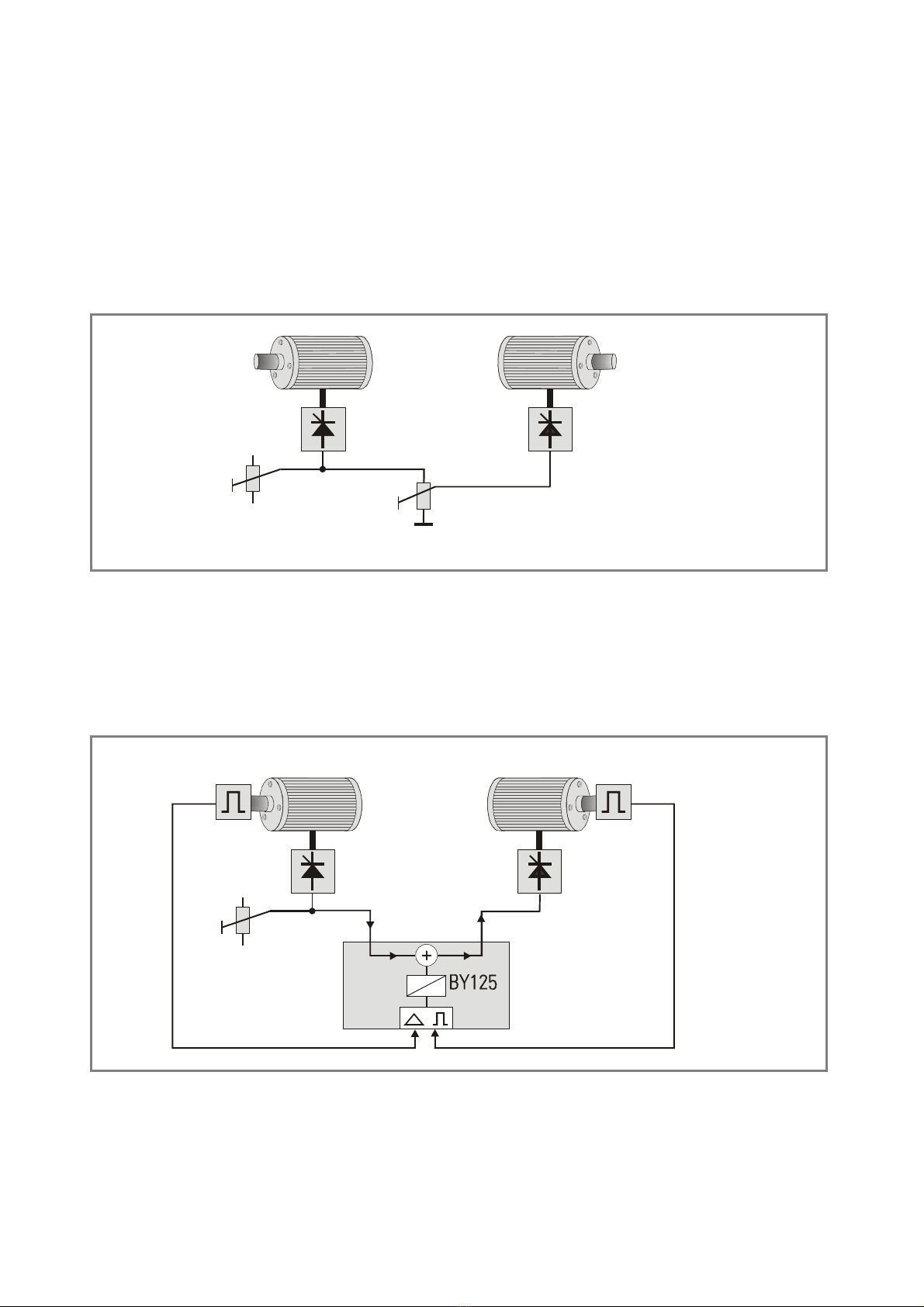
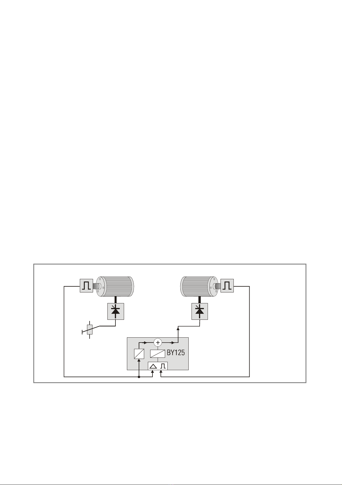
2. Principle of operation..................................................................................................... 6
3. Impulse Scaling.............................................................................................................. 9
4. Ratio Change during Operation.....................................................................................12
5. Change of Phase and Relative Position.........................................................................13
5.1. Timer Trimming (Modes 1 - 4 and 8)..........................................................................................13
5.2. Impulse Trimming (Modes 5 and 6)............................................................................................13
5.3. Phase Offset Operation (Mode3)................................................................................................13
6. Index Control (Modes 2, 6 and 8) ..................................................................................14
7. Connections and Hardware Settings.............................................................................16
7.1. Power Supply..............................................................................................................................17
7.2. Encoders......................................................................................................................................17
7.3. Analogue Input and Output ........................................................................................................19
7.4. The Serial Ports ..........................................................................................................................19
7.5. Control Inputs and Outputs ........................................................................................................21
8. Register List and Clarification.......................................................................................24
8.1. General Parameters....................................................................................................................25
8.2. Setup Registers ..........................................................................................................................29
9. The Front LED................................................................................................................33
10. Remarks about Drives, Encoders, Cables etc. ...............................................................34
10.1. Drives ..........................................................................................................................................34
10.2. Encoders......................................................................................................................................34
10.3. Screening....................................................................................................................................35
10.4. Cables .........................................................................................................................................37
10.5. Remote Signal Commutation .....................................................................................................37
11. Steps for Commissioning ..............................................................................................38
12. Hints for Final Operation...............................................................................................45
12.1. Integrator ....................................................................................................................................45
12.2. Correction Divider.......................................................................................................................45
12.3. Offset voltage .............................................................................................................................45
12.4. Other settings .............................................................................................................................46
12.5. Oscilloscope Function.................................................................................................................46
13. Serial Codes..................................................................................................................47
14. Master Reset and EEPROM Erasure..............................................................................48
15. Dimensions and Specifications.....................................................................................49
16. Appendix: Option UP125 ...............................................................................................50

BY12512d_e.doc / Mai-08 Page 4 / 52
1. Introduction
The BY 125 is a cost-effective synchronizer for high performance synchronization and
registration applications between two independent drives, with a convincing value for price
ratio. The units are suitable for any kind of drives (AC, DC, Servo etc.) that are variable in speed
under control of a 0-10 volts speed reference. The 80 kHz counting frequency allows use of
high-resolution encoders even with high operation speeds. Due to the very short response time
of 120 μsec only, the unit also provides a proper synchronization under highly dynamic
conditions with servo drives.
When on the slave site you use a 1-quadrant-type drive (speed reference always with positive
polarity 0...+10 volts), and your drive uses digital forward/reverse select inputs, please see
“Option UP125” and observe the special hints given in section 18 of this manual.
As a matter of course, full ratio control and other functions like index pulse tracking, print mark
registration and remote phase control are included in the wide set of standard functions.
All settings are fully digital and no potentiometer adjustments are necessary. Programming of
parameters is accomplished by PC/Laptop, using our operator software OS3.x (CD included in
delivery). Remote control is possible by serial communication, e.g. with use of one of our
operator terminals TX720 or BT348. PROFIBUS control is possible with use of the PB251
gateway (see “accessories”)
The mechanical construction uses a closed 19" steel cassette with all connections on its front.
Rack mounting of the cassette therefore does not require use of a swivel frame.
Use of our SM 150 back plane (option) also allows easy DIN rail mounting.
The BY 125 operates from an unstabilized 24 VDC supply (18 V... 30V).

BY12512d_e.doc / Mai-08 Page 5 / 52
(Up to 32 axis)
SlaveMaster
TX720
Operator
terminal
PROFIBUS
BT348
Miniterminal
PC
RS232/485
Possibilities for remote control
of a BY125 synchronizer
When on the slave site you intend to use a 1-quadrant-type drive
(speed reference always with positive polarity 0...+10 volts and digital
forward/reverse select inputs), please refer to “Option UP125” and observe the
special hints given in section 17 of this manual.

BY12512d_e.doc / Mai-08 Page 6 / 52
2. Principle of operation
All operation is based on setting an "analogue synchronization" between the drives first. This
can be achieved by feeding a common speed reference voltage to the drives and tuning the
drive speeds in order to get them into an approximate synchronism. A ratio adaptation may be
necessary for the Slave drive, as shown in figure 1. This analogue pre-synchronization can
match the two speeds within an error range of approx. 1%.
Ratio Adjust
Master
Drive
Speed Reference
Slave
Drive
P1 P2
Fig 1
The digital synchronization now has to compensate for the analogue speed errors in order to
get an absolute, angular and positional synchronization with no drift and no cumulative
displacement of the motor shafts. This needs a digital feedback of the angular shaft position of
the drives. In general, incremental shaft encoders or equivalent signals (e. g. encoder
simulation from a resolver system) are used.
Encoder
Speed Reference
P1
V in
Master Slave Encoder
0-10V 0-10V
V out
AD
E1 E2
Fig 2

BY12512d_e.doc / Mai-08 Page 7 / 52
The synchronizer continuously checks the two shaft positions and immediately responds by an
analogue correction signal when an angular error starts to appear. This analogue correction,
added to the slave’s reference with the correct polarity, will keep the shaft positions of Master
and Slave in line. As the synchronizer responds within only microseconds to each individual
encoder pulse, the slave will practically have no chance to drift away.
Fig. 2 shows that a feed forward signal ”Vin” is needed to run the drives, and a correction
voltage is added to receive the total slave speed reference ”Vout”. It is easy to understand that
the feed forward signal must be proportional to the master speed.
There are three ways to generate Vin:
a) Use of the master speed reference voltage, like shown in Fig. 2. This presumes the
master drive does not use any remarkable internal ramps, because otherwise Vin would
not represent the real master speed upon acceleration or deceleration. As a result,
procedure a) must only be used when the master speed reference already includes the
ramp (generated by a PLC output etc.) and the drive’s internal ramp is set to zero or it’s
minimum value. However, a real speed analogue signal from a tacho generator can be
used at any time.
Analogue feed forward should only be used when replacing older existing BY125 units
against a new one.
b) Use of the frequency- to- voltage converter installed in the BY125 units.
This procedure can be used with most of all applications.
Encoder
Speed Reference
P1 V in
Master Slave Encoder
0-10V 0-10V
V out
AD
E1 E2
Vf
Fig 3

BY12512d_e.doc / Mai-08 Page 8 / 52
The feed forward signal now is generated internally from the frequency of the master
encoder and no external voltage must be applied to the analogue input. This allows the
master drive to use internal ramps, because the encoder frequency always represents
the real actual speed of the master.
Also, procedure b) allows the ”Master” to be just a measuring wheel with encoder, and
not really a drive.
Digital feed forward like shown here requires encoder frequencies of at least 1 kHz at
maximum speed of the master drive. Where we cannot reach this frequency at
maximum speed, slight instability of the synchronization may be the result.
c) Use of an external voltage- to- frequency converter
This procedure is used only exceptionally.
Encoder
Vin
Maesuring
Wheel
Slave Encoder
0-10V 0-10V
Vout
AD
E2E1
Fig 4
With use of our ultra fast precision converter type FU252, also extremely low master
frequencies will be acceptable with no problem.
The mode of generating the feed forward signal can be selected by
register ”LV- Calculation”.

BY12512d_e.doc / Mai-08 Page 9 / 52
3. Impulse Scaling
Both, Master and Slave impulses can be scaled separately, for easy adaptation of the
synchronizer to existing conditions (gear ratios, encoder resolution, roll diameters etc.). The
scaling factor "Factor 1" provides impulse scaling for the Master channel and the scaling factor
"Factor 2" does the same for the slave. Both factors are 5 decade and operate in a range from
0.0001 to 9.9999. Setting them both to 1.0000 will result in a 1:1 speed and phase
synchronizations.
The factors can be set via serial link, using the RS232 or the optional RS485 interface
(ordering number SS124).
Independent of the way of factor setting, the slave always changes its shaft position with
respect to the master according to the following formula:
Slave
=
Factor 1
Factor 2 Master (Proportional - operation)
Slave
=
1
Factor 2 Master
1
Factor 2 (Reciprocal operation)
Proportional or reciprocal operation can be selected by the parameter "LV-Calc "
Remarks to previous formulae:
When positional and angular synchronization is required, we recommend to set SMaster and
SSlave to a number of encoder pulses as received from the encoders when both drives move a
defined synchronous distance or one machine cycle forward.
When only speed synchronization is needed (i.e. speed errors in a range of 0.01% can be
accepted), SMaster and SSlave can also be set to the encoder frequencies at synchronous speed.
For a normal, proportional operation, under consideration of all geometrical machine data, one
would try to fix up the value of Factor 2 in a way to receive a Fact1 scaling directly in
"User units". (Factor 1 is the parameter that would be changed during production, and Factor 2
is a "machine constant" containing all mechanical gearings, which normally would never
change).

BY12512d_e.doc / Mai-08 Page 10 / 52
The following example should explain the calculations for Factor 1 and Factor 2 with a feed roll
system, where the tension of the material should be varied remotely by adapting the slave
speed:
d=300
Master
1024 Imp./rev.
d=100
Slave
500 Imp./rev.
tension
control
Fig 5
With one full revolution of the master must roll, we receive 5 x 1024 = 5120 impulses from the
master encoder. If the material must pass the roll without any tension, the slave roll would
exactly need three revolutions at the same time. So we will get 3 x 2 x 500 = 3000 impulses
from the slave encoder. This means, we need 3000 slave pulses for every 5120 master pulses
to operate synchronously.
We subsequently have to set up Factor 1 and Factor 2 so, that the relation
becomes true. The simplest way to do this is by setting the factors exactly to the digital value
of the impulse numbers from the opposite side, i.e. Factor 1 = 0.3000 and Factor 2 = 0.5120.
Then, the synchronous condition will absolutely match the formula, but there could be little
comprehension from the operator, that he needs to set a value of 0.3000 on his terminal to
have tension-free synchronism. He would understand more clearly, if the setting was 1.0000.
So, we need to use the formula with different figures:
As a result we find that Factor 2 must be 5120 : 3000 = 1.7067. This setting calibrates the
Factor 1 to comprehensible "user units" (1.0000 = no tension, 1.0375 = 3,75% tension).
The same result can be achieved when using the parameter "F1-Scaling Factor" to scale the
values transmitted from the operator terminal (see chapter 8.1).

BY12512d_e.doc / Mai-08 Page 11 / 52
Hint 1:
It is best, whenever possible, to have Factor 1 and Factor 2 in a numeric range of
0.1000 - 2.0000. This allows the BY to use the full 12 Bit resolution of all D/A
converters. When, for example, the factor calculation results in figures like
4.5000 and 7.8000, it is better to set 0.4500 and 0.7800 (or 0.9000 and 1.5600 or
any other proportional values within the recommended range) to ensure best
operation.
Hint 2:
Whenever a positional synchronization is needed, cumulative errors must be
avoided by proper factor setting (factors can only be set with 4 digits to the right
of decimal point).
If, e.g. a ratio of 16 : 17 would be required, never use the decimal expression of
0.94117647...for Factor 1, because the non-entered digits will accumulate to give
positional errors after a short time. This can be completely avoided when using
factors like 1.6000 and 1.7000 (or also 0.8000 : 0.8500 etc.).
This hint needs not be observed with speed synchronization alone, because
speed errors will remain undetectable small.
Hint 3:
It is best to choose the ppr number of the encoders to receive frequencies in
approx. the same range on both sides. It can e.g. become difficult to synchronize
100 Hz on one side with 80 kHz on the other side.

BY12512d_e.doc / Mai-08 Page 12 / 52
4. Ratio Change during Operation
The speed ratio can be changed at any time by changing Factor 1 via serial link. Changing
Factor 1 from 1.0000 to 2.0000 will result in double slave speed. The speed transition can be
sudden or soft. The slave approaches its new speed via an adjustable sin² ramp. See parameter
"Ramp1".
When using operation mode 4, the speed ratio can also be changed via remote push buttons or
PLC signals. In this mode, any activation of the „Index Master“ and „Index Slave" hardware
inputs will cause Factor 1 to continuously increment or decrement. Upon release of the Trim
command, the latest scaling factor will be responsible for the speed ratio.
The speed of incrementing / decrementing can be set by the register "Trim Speed". At any time,
the operative scaling factor can be stored to the EEPROM by hardware signal or software
command. This facility ensures later use of the same speed ratio, also after power down.
To avoid wrong operator settings or exceeding of given limits, Factor 1 range can
be limited by the parameters Factor 1 Minimum and Factor 1 Maximum.

BY12512d_e.doc / Mai-08 Page 13 / 52
5. Change of Phase and Relative Position
The relative phase situation between Master and Slave is normally set by the state upon
power-up or with the last Reset signal (with index modes, the index edges and the programmed
phase displacement define the relative position, see chapter 6.)
During all the operation, this initial phase condition is held without any errors,
unless the operator uses one of the following facilities to change this condition
5.1. Timer Trimming (Modes 1 - 4 and 8)
This function, activated by the "Trim +" and "Trim -" inputs, provides a temporary higher or
lower slave speed which results in a phase displacement between the motor shafts. When
releasing the trim buttons, the drives will synchronize again in their new relative position. The
differential trim speed is generated by an internal timer and is adjustable. It operates as a
speed addition or a subtraction to the slave, without consideration of the actual absolute
speed. This is why the trim function can also be used at standstill, to move the slave into a
convenient start-up position.
5.2. Impulse Trimming (Modes 5 and 6)
The ”Trim +” and ”Trim -” inputs accept external pulses from a pulse generator, encoder or a
PLC. Every pulse applied to one of the Trim inputs will shift the phase exactly one encoder
increment forward or backward. This procedure provides repeatable changes and adjustments
of the phase situation between the drives, e.g. under control of an external impulse counter or
a PLC. Modes 5 and 6 can also be used to realize the function of a differential gearbox.
5.3. Phase Offset Operation (Mode3)
The unit provides an Offset register, which can be set to a desired number of encoder impulses.
Every rising edge at the ”Index Master” input will displace the actual phase forward by the
number of offset impulses, and every rising edge at the ”Index Slave” input will do the same to
the other direction. By this function, the phase situation can be stepped forward or reverse by
the pitch set to the offset register (e.g. in steps of one or several angular degrees).

BY12512d_e.doc / Mai-08 Page 14 / 52
6. Index Control (Modes 2, 6 and 8)
Index or marker pulses are used to automatically set the drives or the material into a correct
relative position. It is possible to either use the zero pulse inputs on the encoder terminals
(Z and /Z, 5 VTTL) or the index inputs on the screw terminals (10...30 V), and the parameter
”Index Mode” selects which inputs are in use.
It is possible to enter the phase displacement between the marker pulses by PC or host
computer, and to change it at any time, at standstill or on the fly (Register "Phase offset“).
Offset
K = impulses between two
master index
N = impulses between two
slave index
Master
Index
Slave
Index
Fig 6
The parameter Factor 1 is used to align different impulse numbers Kand Non both encoders.
The number of slave impulses N must be set to register ”Impulse Index”.
The formula Fig. 6 shows how to calculate Factor 1. The offset needs to be set directly as
"number of slave impulses" and has a setting range from -N to +N which means -360° to +360°
of displacement.
Between two marker signals, the drives operate in a normal digital synchronism. The master
impulses are scaled with Factor 1, but the slave impulses count with a fixed factor of 1,0000 in
all Index modes.
A positive edge on the slave index input starts a phase comparison with the previous master
index and a correction, if not coincident to the offset M. Additional phase adjustment, as
described under sections 5.1 and 5.2, is also possible in index mode. I. e., starting from an
initial phase position, the final phase can be easily tuned, by pushbuttons or PLC, if applicable.
The new phase can be restored to the phase offset register by a store command.

BY12512d_e.doc / Mai-08 Page 15 / 52
As a special, the BY 125 can even operate with different number of marker pulses on both
sides. This is possible due to the following features:
a. The master index input is equipped with a programmable index divider, which, for
example, allows sampling of only each fifth marker pulse.
b. The slave index input is locked in a way that it becomes active only once after each
valid master marker pulse.
This enables the user, in terms of one machine cycle, to have for example five master markers
and three slave markers. Upon start up, the BY 125 checks for the nearest marker couple and
sets them in line. Subsequently, each fifth master index will be checked with each third slave
index.
Operation mode 8 provides a fully unlocked function of the index inputs and every couple of
marker impulses will cause a correction, no matter if the master leads the slave index or vice-
versa.
This mode needs setting of a ”maximum index error” to the ”Impulse Index” register (setting in
slave encoder increments). Errors higher than the maximum index error setting will not be
corrected with this mode. The differential speed to correct for the index error can be set by
register ”Trim speed”.
Mode 8 is perfectly suitable for compensation of wheel slip with large cranes (reference marks
on the rails) and to equalize different distance between products when passing from one
conveyor to another.
Sensor “Edge of product” = Index Master
Sensor “Pitch of chain” = Index Slave
Master Slave
Application of mode 8 to control distance between products.
Fig.7

BY12512d_e.doc / Mai-08 Page 16 / 52
7. Connections and Hardware Settings
1 2 3 4
S1 (encoder settings)
S2 (RS 485 setting)
(optional)
Master encoder
(9-pos. male)
Slave encoder
(9-pos. male)
Serial port
(9-pos. female)
Screw
terminal
strip
LED
Fig 8
Fig. 8 shows the connectors available on the front plate, Fig. 9 shows the block diagram of the
unit with its minimum peripheral configuration and Fig. 10 shows the screw terminal
assignment.
A/A B/BZ/Z+-
3219 645
GND10V
Master
+
-
Analogue Master
Com +
Ready
+24V out
+ 5V out
Opto
Alarm
Out of sync
.
Index o.k.
Opto
Opto
Opto
A/A B/BZ/Z+-
3219 645
GND10V
Slave
+
-
Analogue Slave
Not necessary
when digital
feed forward
is selected
GND
Power supply24 VDC
Reset
Trim+
Trim-
IndexMaster
IndexSlave
StoreEEProm
GND
GND terminals
Serial
+24V
out
Control inputs
Control inputs
VCC
Bold printed numbers = screw terminal
77
Fig.9

BY12512d_e.doc / Mai-08 Page 17 / 52
7.1. Power Supply
The BY 125 operates from an unstabilized 24 VDC supply (+/- 25%); however, the voltage
including ripple should not exceed the following limits (18 V...30 V). The supply of the BY 125 is
electrically protected against wrong polarity misconnection by protection diodes.
GND
+ 24VDC (Power supply)
GND
VCC out (+5,5V)
Trimm +
Trimm -
Index Master
Index Slave
Reset
Store EEProm
+ 24VDC
GND
GND
GND
Analogue GND
LV IN (Analogue Feed Forward)
GND
LV OUT
+ 24VDC
Com +
Ready
Alarm
OUT Sync
Index o. k.
Do not connect when you use digital feed forward
signal from the internal f/V converter
Fig 10
7.2. Encoders
The unit only accepts 5V differential TTL signals or similar signals from an encoder simulation
of a drive. It is essential to connect the channels A, /A, B, /B at any time. The zero input
channels Z and /Z can be omitted, if not needed.
An auxiliary voltage of 5.5 V (max. 500 mA totally) is available on the connector plugs "Master"
and "Slave", for easy supply of the encoders. Both connectors on the unit are Sub-D-9 pin, male.
Where you find you are working with existing 10-30 Volt encoder signals that feature only A, B
and Z signals, the PU 202 converter should be used to gain full complementary signals in line
with RS422 standards. Against special order designation, BY125 units can also be delivered
with HTL encoder inputs: Option HTLIN1 provides inputs A, B, Z with 24V level (inverted
channels not connected) and option HTLIN2 provides all six channels including the inverted
ones with 24V level. With these options, the 24V power supply of the unit is connected to
master and slave encoder connectors to supply the encoders.

BY12512d_e.doc / Mai-08 Page 18 / 52
Fig. 10 and Fig. 11 show the encoder connections and the principle of the input circuit.
When connecting the encoders it is not important to wire the A and B signals to produce the
correct counting direction. The direction can be determined in the setup menu.
/Z
S1 DIL
Z/B
12345
9867
4
3
2
1
B/AA
/Z Z /B
12345
9867
B/AA
GND
VCC
Fig. 11
A
1K
33R
1K
VCC
/A
5
GND int.
4
VCC
Input circuit (principle)
Input current 6 mA
33R
Fig. 12
For screening, please refer to section 12.3
The 4-position DIL switch S1 allows the desired encoder voltages to be set.
Correct switch settings are essential for proper function. See Fig. 8.
•With encoders, supplied by the BY 125:
Set positions 1 and 3 to "ON" (Master)
Set positions 2 and 4 to "ON" (Slave)
Connector pins 4 and 5 provide the encoder supply.
•With encoders supplied by external source, or with encoder simulation from the drive:
Set position 1 to "OFF" and position 3 to "ON" (Master)
Set position 2 to "OFF" and position 4 to "ON" (Slave)
Use connector pin 5 as common GND potential.

BY12512d_e.doc / Mai-08 Page 19 / 52
•For fully differential operation (RS422):
Set positions 1 and 3 OFF (Master)
Set positions 2 and 4 OFF (Slave)
The inputs then operate in differential mode, which is best in terms of noise immunity.
However, the impulse source must be of line driver type with external supply, when this input
mode is used.
When switch positions 1 and 2 are "ON", you must ensure that no supply is
applied to pins 4 and 5, as this will cause serious damage within the unit.
7.3. Analogue Input and Output
The analogue input and output signals can be found on screw terminals 16 and 18.
The Analogue common GND is internally connected to the minus of the 24 VDC supply.
All analogue levels are in range +/- 10 Volts.
LVin (Terminal 16) :
Receives a voltage proportional to the master speed e.g. master
reference voltage or line tacho signal (+/- 10 V range), when you use
analogue feed forward.
Remains unconnected when you select digital feed forward
LVout (Terminal 18) : This output supplies the slave with its speed output reference
voltage. When the "Gain Corr" is set to any value except 0, the digital
correction voltage is superimposed to this output.
7.4. The Serial Ports
Delivery always includes a RS232 interface. Also an additional RS485 interface is available
(option SS 124). Both serial links use the same connector for wiring. Serial communication is
possible with both interfaces at a time in an alternating sequence (dialogues must not overlap).
+5V
12345
98 67
GND ext.
GND
int.
TxD RxD
T+ T- R+ R-
Serial interface connector
Fig. 13
The serial link must be used for PC set-up of the registers upon commissioning, with use of the
operator software OS3.x

BY12512d_e.doc / Mai-08 Page 20 / 52
It can be used for on-line operation with a master computer, a PLC or an operator terminal
(e.g. BT348 or TX720 or other), accessing all registers and control functions.
The serial communication protocol uses the Drivecom standard (ISO 1745), which is wide-
spread in drive industry.
Before running the BY125 with an RS 485 bus, some adjustments are necessary. Open the right
hand side plate. The optional RS 485 interface card with the 8-position DIL switch S2 is located
at the right-hand side of the main board (see Fig. 8).
The desired bus type and potentials can be set there.
12345678
Computer
12345678
Computer
12345678
Computer
R
R
T
T
R
R
R
R
T
T
Table of contents
Other Motrona Recording Equipment manuals
Popular Recording Equipment manuals by other brands

TTS
TTS Talk-Tracker user guide

SoundCraft
SoundCraft 1624 Series user guide

Focusrite
Focusrite Scarlett 2i4 user manual

F-Pedals
F-Pedals DARKLIGHT user guide

Flamco Meibes
Flamco Meibes Logotherm Logo Basic 30 kW Technical information for installation and operation

Sound Devices
Sound Devices 788T User guide and technical information