Motrona ZU 251 Series User manual

control – motion – interface
ZU25102A_e.DOC / Mrz-08 Page 1 / 26
ZU 251
Incremental Counter Module
With Analogue Output and Serial Interface
•Counter suitable for quadrature signals (A/B, 90º) as well as single channel inputs
•Counting inputs selectable to TTL/ RS422 format or to HTL / 10-30 volts format
•Maximum counting frequency 500 kHz
•Analogue outputs +/-10 V, 0-20 mA and 4-20 mA, polarity following the sign of the
internal counter
•Analogue conversion time 1 msec only
•RS 232 and RS 485 interfaces for serial readout of the counter
•Also suitable for conversion of the sum or the difference of two separate counts
•Facility for free linearization of the analogue output by 16 interpolation points
•Easy to set up by TEACH procedure, or by PC and Windows software
Operating Instructions
ELEKTRO-TRADING sp. z o.o
Tel. +48 (0-32) 734-55-72
Tel/Fax +48(0-32) 734-55-70
E- ail [email protected]
http://www.elektro-trading.com.pl

ZU25102A_e.DOC / Mrz-08 Page 2 / 26
Safety Instructions
•This manual is an essential part of the unit and contains important hints about
function, correct handling and commissioning. Non-observance can result in
damage to the unit or the machine or even in injury to persons using the
equipment!
•The unit must only be installed, connected and activated by a qualified electrician
•It is a must to observe all general and also all country-specific and application-
specific safety standards
•When this unit is used with applications where failure or maloperation could cause
damage to a machine or hazard to the operating staff, it is indispensable to meet
effective precautions in order to avoid such consequences
•Regarding installation, wiring, environmental conditions, screening of cables and
earthing, you must follow the general standards of industrial automation industry
•- Errors and omissions excepted –
Version: Description:
ZU25101B/ HK/AF/ Nov.01 Original version
ZU25102A/ HK/AF/ Mar04 New parameters: Power-up-Mode, Protocol setting

ZU25102A_e.DOC / Mrz-08 Page 3 / 26
Table of Contents
1. Introduction....................................................................................................4
2. Applicable encoders and sensors ..................................................................5
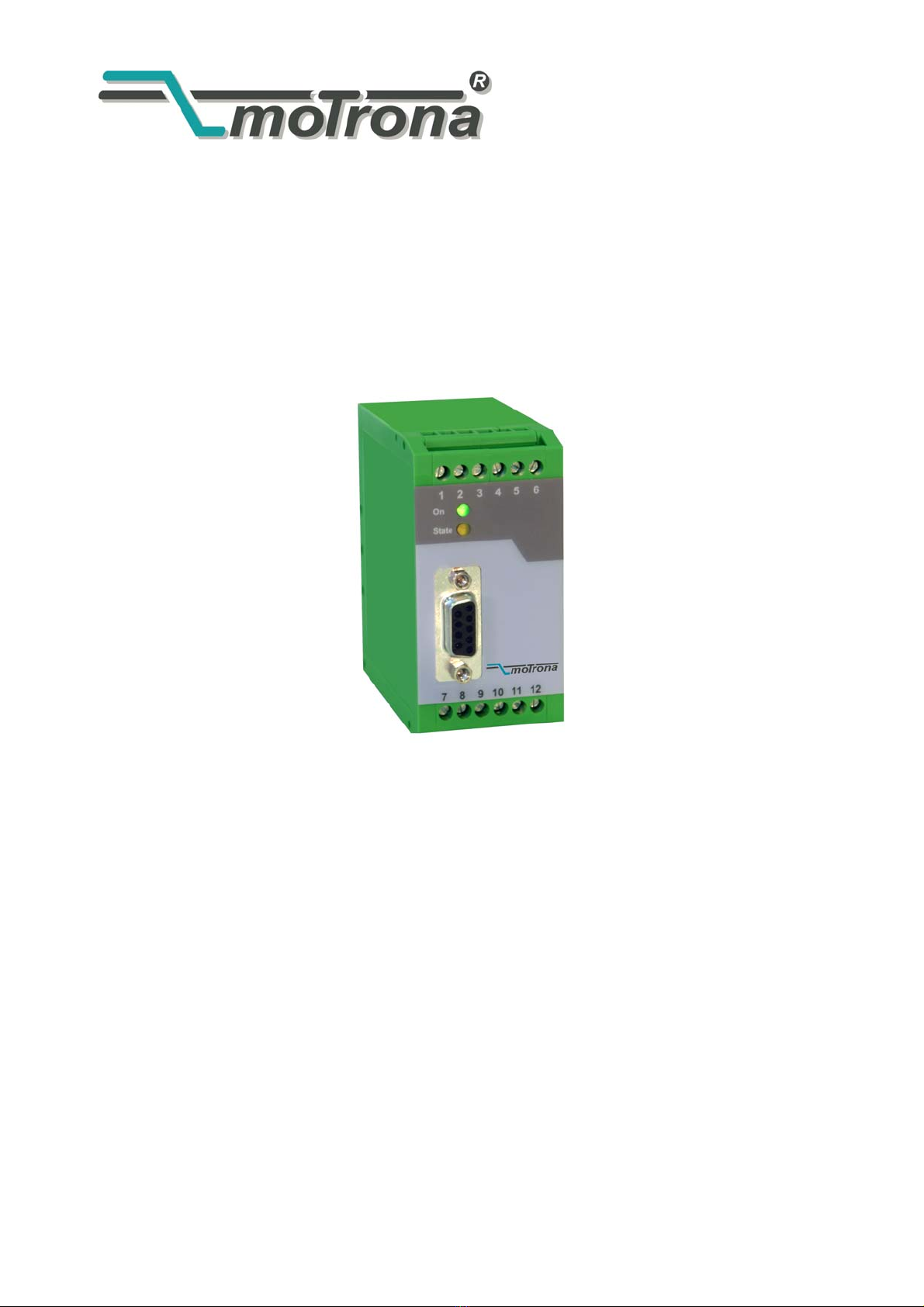
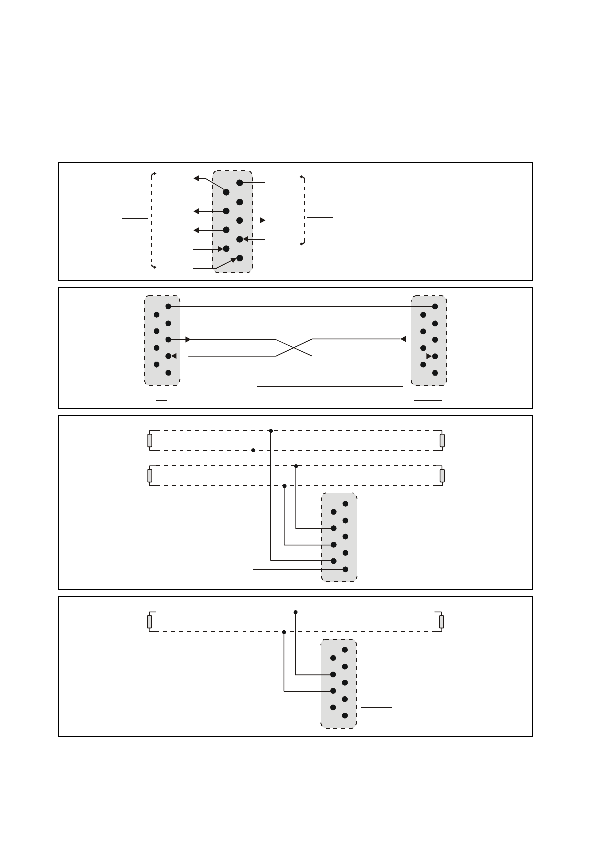
3. Terminal Assignment .....................................................................................6
3.1. Incremental encoders TTL / RS 422 ......................................................................6
3.2. Incremental encoder HTL / 12-30V .......................................................................7
3.3. Proximity switches, photocells etc........................................................................7
3.4. Analogue outputs ..................................................................................................7
3.5. Serial interfaces ....................................................................................................8
4. DIL switch settings.........................................................................................9
5. Setup Procedure........................................................................................... 11
5.1. Operation as single channel counter (without direction signal)
or as positional counter (with direction signal)...................................................12
5.2. Operation as a summing or differential counter with
two independent impulse inputs (A+B, A-B).......................................................12
6. Readout of the actual counter state by serial communication ..................13
7. PC setup with use of the operator software OS3.x.....................................14
8. Displays and Softkeys..................................................................................15
9. Parameter Settings ......................................................................................16
10. Free Programmable Linearization.................................................................21
11. Test Functions.............................................................................................. 23
12. Dimensions .................................................................................................. 24
13. Technical Specifications ..............................................................................25
14. Parameter List.............................................................................................. 26

ZU25102A_e.DOC / Mrz-08 Page 4 / 26
1. Introduction
ZU 251 represents a small and low-cost, but highly performing converter for industrial
applications, where incremental counting of positions or events must be converted to either
analogue format or serial data. The unit has been designed as a compact module with 12 screw
terminals and a 9-position SUB-D connector (female). The housing is suitable for standard DIN
rail mounting.
The impulse input side provides channels A, B and also the inverted lines /A, /B which must be
used with TTL/ RS422 input signals. The unit can count and convert the following formats to
analogue and serial:
a. Up/down count with quadrature input (A/B, 90°).
The polarity of the analogue output and the sign of the serial data depend on the sign of
the actual counting result
b. Single channel impulses on channel A.
Input B sets the counting direction and therefore also the polarity of the output
(LOW = negative, HIGH = positive).
Please observe:
•Open NPN inputs are HIGH
•Open PNP inputs are LOW
•Open RS422 inputs are HIGH
c. Dual count of fully independent events on channels A and B, where the output signal
represents the sum or the difference of both counts.
A
B
A
B
A
B
A and B, quadrature 90° A=impulse, B=static direction signal A and B: independant counting events
a
.
b
.
c
.
+
-
The definitions for “zero analogue output” and “full scale analogue output” definition can be
set over the full counting range of +/-8 decades (-99 999 999 to +99 999 999)

ZU25102A_e.DOC / Mrz-08 Page 5 / 26
2. Applicable encoders and sensors
The converter can accept the following impulse sources:
•Encoders with HTL level output (12–30V) and either PNP or NPN or Push-Pull or NAMUR
characteristics, using quadrature output signals A and B
•TTL / RS422 encoders providing the output lines A, /A ,B and /B
•Single channel sources like proximities or photocells, providing HTL output and PNP or
NPN or NAMUR characteristics
•Single channel sources with TTL/ RS422 output, providing both, signal and inverted
signal (differential operation)
In general, HTL encoders will be supplied from the same source as the converter itself.
For supply of TTL encoders, the unit provides an auxiliary output of 5.5 volts stabilized,
(150 mA max.)
For applications using single-ended TTL signals A, B only (i.e. without
associated inverted signals /A, /B) : See successor model ZU252

ZU25102A_e.DOC / Mrz-08 Page 6 / 26
3. Terminal Assignment
We recommend connecting the Minus wire of the power supply to earth potential.
Please observe that, under poor earthing and grounding conditions, multiple earth connections
of screens and GND terminals may cause severe problems. In such cases it may be better to
have only one central earthing point for the whole system.
GND terminals 4, 6 and 12 are connected internally. Depending on input voltage and load of the
auxiliary voltage output, the total power consumption of the unit is approx. 150 mA
(see specifications).
123456
789101112
Analogue out +/-10V
TTL: Input /B HTL: n.c.
TTL: Input B HTL: Input B
Analogue GND ( - )
+18...30 VDC (typ. 200 mA)
GND ( - )
0-20mA / 4-20mA out
TTL: Input /A HTL: n.c.
TTL: Input A HTL: Input A
Reset
Aux. 5.5V out (max. 150 mA)
GND ( - )
POWER
3.1. Incremental encoders TTL / RS 422
If applicable, the encoder can be supplied from the ZU251 converter. Where the encoder is
already supplied from a remote source, we recommend fully differential operation, with no
GND connection between encoder and converter (see figures a. and b.)
8
9
2
3
11 (+5.5V)
12 (GND)
+
-
TTL encoder ZU 251 converter
Screen
A
A
B
B
A
A
B
B
a)
8
9
2
3
11 (+5.5V)
12 (GND)
+
-
TTL encoder ZU 251 converter
Screen
A
A
B
B
A
A
B
B
b)
+ext
-ext

ZU25102A_e.DOC / Mrz-08 Page 7 / 26
3.2. Incremental encoder HTL / 12-30V
The encoder may be supplied from the same source as the converter, or from another source.
9
3
12 (GND)
GND
HTL encoder
ZU 251 converter
Screen
+24V
+
A
B
3.3. Proximity switches, photocells etc.
This connection is fully similar to a HTL incremental encoder. With single-channel operation,
input B remains unconnected or can be used to select the output polarity. With use of two
independent counting events for forming the sum or the difference, input B operates as the
second counting input.
For use of sensors providing 2-wire NAMUR characteristics:
•Set the inputs to HTL and NPN
•Connect the positive wire of the sensor to the corresponding input and the negative
wire to GND.
3.4. Analogue outputs
The unit provides a +/-10V voltage output and a 0-20 mA / 4-20 mA current output at a
resolution of 14 bits, i.e. the voltage output operates in steps of 1.25 mV and the current output
operates in steps of 2.5 μA. The nominal load of the voltage output is 2 mA, the current output
accepts loads between 0 Ohms and 270 Ohms.
The analogue ground uses a separate terminal, which however internally is connected to the
GND potential of the power supply.
GND
4
1
7
+/- 10V
20 mA
(R = 0 - 270 Ohms)
(Imax = 2 mA)
Screen
Vout
Iout

ZU25102A_e.DOC / Mrz-08 Page 8 / 26
3.5. Serial interfaces
The unit provides a RS232 interface and a RS485 interface, however only one of the two can be
used at a time. Serial communication allows to read out the counting result and to set
parameters and variables by PC, according to need.
54321
9876
GND int.
TxD
RxD
RS232
+5V
T+
T-
R+
R-
RS485 Sub-D-9 (female on unit site)
54321
9876
54321
9876
54321
9876
54321
9876
GND
TxD
RxD
PC ZU 251
RS232: Please connect only pins 2, 3 and 5 !
54321
9876
54321
9876
T+
T-
120 Ohms 120 Ohms
RS485- Bus
( 4- wire )
ZU 251
120 Ohms 120 Ohms
R+
R-
T+
T-
R+
R-
54321
9876
54321
9876
T+
T-
120 Ohms 120 Ohms
RS485- Bus
( 2- wire )
ZU 251

ZU25102A_e.DOC / Mrz-08 Page 9 / 26
4. DIL switch settings
The DIL switch located on the top site of the unit provides customer-specific settings of the
desired operation modes.
Changes of the switch settings will become active only after the next
power-up cycle!

ZU25102A_e.DOC / Mrz-08 Page 10 / 26
Quadrature A/B, 2x90°
A + B
A = impulse, B = direction
Unit loads default settings with every power up cycle
No loading of default settings upon power-up
Push button and LED operating in Teach mode
Teach function disabled, LED testing inputs A and B
NPN (switch to -)
PNP (switch to +)
VALUE" after power down Counter sets to “RESET”
Counter stores actual data upon power down
HTL ( 12 - 30 V )
TTL / RS 422
RS 232
RS 485
12345678
The switch settings shown in the example are suitable for a quadrature encoder with HTL- and
NPN characteristics. The power-down memory is switched off and the serial link is set to
RS232 communication.
After setup and commissioning, please set DIL switch position 6 to ON.
If set to OFF, any inadvertently touch of the „Teach“ button would overwrite
your previous scaling input !
*) These settings refer to the impulse inputs A/B only. The RESET input (terminal 10) however always uses
HTL and PNP characteristics and you must apply a voltage of 12 to 30 volts to activate the Reset function.

ZU25102A_e.DOC / Mrz-08 Page 11 / 26
5. Setup Procedure
For all basic applications you can use the Teach feature for commissioning of the unit.
Extended functions need a PC for setup and are described under section 7.
As a first step it is advisable to check the input pulses by means of the LED marked “Status”.
DIL switch 6 must be set to ON for this test.
When you press the TEACH button one time, the yellow LED will be lit after the unit detected a
pulse on input A. The LED will be OFF when no input pulse has been detected.
When you press the TEACH button once more, you can also check input B (if applicable). With
use of mode A+B and two independent impulse sources, again the yellow LED will be lit after a
pulse has been detected on input B.
With operation modes using input B to define the direction and polarity (quadrature or static),
the yellow LED will indicate that the actual input signals provide a positive signal on the
analogue output (LED on) or a negative signal (LED off). Where you like to get the other polarity,
you must change the information of direction on A/B inputs

ZU25102A_e.DOC / Mrz-08 Page 12 / 26
5.1. Operation as single channel counter (without direction signal)
or as positional counter (with direction signal)
•Settings: Make sure that the DIL switch is set according to the encoder in use, and that
DIL switch position 6 is OFF (Teach function active).
•Self test: Upon power up, both front LED’s must be lit first, and the yellow status LED
must switch off after the self-test has been concluded successfully (approx.1 sec.).
•Scaling of the analogue output with use of the Teach function:
Press the Teach button one time. The status LED will blink in a slow sequence now
while the unit waits for setting of the minimum counter state, this is the state where
later you expect the analogue output to be zero (in general, this will be with counter=0).
Please set the counter to the desired state or move the encoder to the desired position
and reset the counter to zero. Then press the Teach button again. This stores your
minimum counter definition.
The LED will blink in a fast sequence now and the unit waits for setting of the maximum
counter state, this is the state where later you expect full scale analogue output.
Please get the counter to the desired state or move your encoder to the desired position.
Then press the teach button once more. This stores your maximum counter definition
and the LED will switch off.
After this Teach procedure, your analogue output is set to 0–10 volts swing between the
minimum and the maximum counter state.
5.2. Operation as a summing or differential counter with
two independent impulse inputs (A+B, A-B)
In principle, the Teach procedure is exactly the same as shown under 5.1, but the minimum and
maximum counter states already refer to the sum or the difference of the count on both inputs.

ZU25102A_e.DOC / Mrz-08 Page 13 / 26
6. Readout of the actual counter state by
serial communication
At any time you can read out the actual counter state and more values via serial link. For
setting of serial communication parameters etc., you must however apply PC setup anyway, as
shown later.
ZU 251 uses the DRIVECOM communication protocol according to the ISO 1745 standard.
Details about the protocol can be found in our document “SERPRO.doc”, available for download
under
www.motrona.com
The following register codes are available for readout:
C1 C2 Description
: 8 Actual conversion result, scaled as % of full scale output, format xxx.xxx % *)
: 9 Actual counting result
; 3 Actual output voltage of the analogue output, scaling 0 – 10 000 millivolts
*) under consideration of the scaling operands as shown in section 9.
+/-Operand
Readout from <:8>
=
Counter result in % of full scale
x
xOperand
/Operand
+

ZU25102A_e.DOC / Mrz-08 Page 14 / 26
7. PC setup with use of the operator software
OS3.x
You can apply the full set of functions when you use a PC and our operator software OS3.x for
setup of the unit (actual software version is OS3.2).
You can download this software and more instructions from our homepage
www.motrona.com
Connect your PC to the converter, using a serial RS232 cable like shown in section 3.5 of this
manual. Make sure the cable only uses pins 2, 3 and 5. Pins 2 and 3 must be crossed.
Run the OS3.x software and you will see the following screen:
If your text and color fields remain empty and the headline says „OFFLINE“, you must verify
your serial settings and the DIL switch setting. To do this, select „Comms“ from the menu bar.
•Ex factory, all motrona units use the following serial standard settings:
Unit No. 11, Baud rate 9600, 1 start/ 7 data/ parity even/ 1 stop bit
•If the serial settings of your unit should be unknown, you can run the
„SCAN“ function from the „TOOLS“ menu to find out.

ZU25102A_e.DOC / Mrz-08 Page 15 / 26
8. Displays and Softkeys
The edit window for all unit parameters can be found on the left side of the screen.
The INPUTS field shows the softkeys to switch the control commands on or off. Display boxes
in the RS column indicate when the corresponding command is set to ON by PC. Display boxes
in the PI/O column indicate that the corresponding command is ON by external hardware.
The boxes in the OUTPUTS field provide information about the state of the unit, where “Status
A” and “Status B” are especially useful to check the counting inputs:
•Status A is lit when a counting pulse is detected on input A
•Status B is lit when a counting pulse is detected on input B
•For input modes using direction information, Status B is lit when the actual direction of
the input corresponds to forward count in the positive sense.
The color bar graph displays the actual output state in a range of +/- 100 % of full scale.
Control keys are available for readout, transmission and storage of parameters.

ZU25102A_e.DOC / Mrz-08 Page 16 / 26
9. Parameter Settings
Parameter Description
Display Setting:
x Operand
/ Operand
+/- Operand
These operands allow to convert the result to the desired engineering units.
The conversion affects the numeric value for serial read out from register
<:8> only, but not the scaling of the analogue output.
With settings x operand = 1.0000
/ operand = 1.0000
+/- operand = 0.0000
the readout from register < :8 > equals to the percentage result (xxx.xxx%) ,
where 100,000% has been defined by the TEACH minimum and TEACH
maximum settings
+/-Operand
Readout from <:8>
=
M ea s ur in g re s ult i n % of f ul l s cal e
x
xOperand
/Operand +
General Setting
Teach Minimum
Teach Maximum
This couple of settings define your minimum and maximum count for input
A and input B (if applicable), where your analogue output moves from 0 V
to 10 V.
You can enter your minimum and maximum settings as follows:
•either by operating the Teach pushbutton
(like described already under 5.1)
•or by entering the counter settings directly by keyboard to the
parameter field of your screen, without using the TEACH function.
When using summary or differential counting modes (A+B, A-B), these
settings already refer to the sum or the difference of the counter.

ZU25102A_e.DOC / Mrz-08 Page 17 / 26
Parameter Description
Output Mode: Selects the output format of the analogue outputs as shown:
V
Encoder
Min.
Max.
Output Mode = 0
-10V ... 0 ... +10V
Encoder
Min. Max.
V
Output Mode = 1
0 ... +10V
Min. Max.
mA
Encoder
Output Mode = 2
4 ... 20 mA
mA
Encoder
Max.
Min.
Output Mode = 3
0 ... 20 mA
Linearization
Mode:
Sets the mode of linearization.
0: Linearization off, registers P1 to P16 do not affect the output
characteristics.
1: Linearization in a range of 0 – 100%
2: Linearization over full range –100% to +100%
See example under section „Linearization“
Factor A
Factor B:
Impulse scaling factors for the two counter inputs.
Setting 1.0000 results in one increment with every input pulse, whereas
setting 0.5000 would need 10 input pulses to increment by 5 etc.
1/4 Edge Mode:
This setting, with use of quadrature A/B input, allows simple count (x1) or
full quadrature count (x4), by either accepting rising edges from input A
only, or all rising and falling edges from inputs A and B
0 = simple count (x1)
1 = quadrature count (x4)
AB Mode:
Sets the counting mode with two independent single-channel inputs
0 = no combination
1 = sum A + B
2 = difference A – B
DIL switch positions 2 and 3 must be set correspondingly.
Reset Mode:
Sets the behavior of the Reset input:
0 = static reset with “high” level
1 = dynamic reset by rising edge *)
2 = dynamic reset by falling edge *)
3 = dynamic reset by rising edge **)
4 = dynamic reset by falling edge **)
Settings 1 and 3:
Settings 2 and 4:.
*) The duration between the active edge and the zero state of the analogue output is 5 msec.
During this internal processing period the analogue output may make undefined jumps
**) The duration between the active edge and the zero state of the analogue output is 10 msec,
but there will be a defined zero approach with no jumps

ZU25102A_e.DOC / Mrz-08 Page 18 / 26
Parameter Description
Reset Value:
With every reset command, the counter presets to the datum set here
(e.g. 000 000) and the analogue output follows the new counter state
according to its output scaling.
Round Loop:
This register limits the counting range to a repeating loop. With setting of
1000, in upwards direction 999 is followed by to 000, and in downwards
direction the counter sets to 1000 when reaching zero.
Setting this register to 000 000 provides counting over the full range.
Power up Mode:
Sets the action of the counter upon power up:
0 = Loads the previous value from power down memory
1 = sets counter to zero
Set-Up-Settings:
Analogue Offset:
Allows adjusting the analogue zero output in a range of approx. +/- 100mV
(respectively +/- 200 μA) if necessary.
Analogue Gain:
Sets the maximum output swing of the analogue output. Setting of 1000
results in a 10 volts respectively 20 milliamps output swing.
Direction:
Can be used to invert the polarity of the analogue output signal when
converting quadrature A/B input signals or A=impulse and B=direction.
0 = no inversion of the polarity
1 = inversion of the polarity

ZU25102A_e.DOC / Mrz-08 Page 19 / 26
Parameter Description
RS232 / RS485
Setting:
Unit Number:
Especially with RS 485 applications it is necessary to attach a specific
address to each unit, since up to 32 units can be connected to the same
bus. You can choose any address number between 11 and 99.
Factory setting = 11
The address must not contain a “0“ because these numbers are reserved for
collective addressing.
Setting Baud
0* 9600
1 4800
2 2400
3 1200
4 600
5 19 200
6 38 00
Serial Baud
Rate:
* = Factory setting
Setting Data bits Parity Stop bits
0* 7 even 1
1 7 even 2
2 7 odd 1
3 7 odd 2
4 7 none 1
5 7 none 2
6 8 even 1
7 8 odd 1
8 8 none 1
9 8 none 2
Serial Format:
* = Factory setting
Protocol Setting:
The serial port of the unit can operate in either “PC-Mode“ or in “Printer
Mode“.
With “PC-Mode“, the unit waits for a request string and responds with a
corresponding data string. For details of the protocol see description
“SERPRO“.
With “Printer Mode“ the unit sends data without any request and under
Timer control as described subsequently.
As soon as the unit receives a character, it automatically switches to PC
Mode and operates according to protocol. When for a period of 20 sec. no
character has been received, the unit switches automatically to “Printer
Mode“ and starts cyclic data transmission.

ZU25102A_e.DOC / Mrz-08 Page 20 / 26
The following register settings control the automatic cyclic transmission of internal register
values by serial interface to peripherals like printers or displays.
Parameter Description
Serial Protocol: This register selects the serial protocol for the cyclic transmission.
When set to 0, the string starts with the serial address of the unit (“Unit
Number”), followed by a space and the value of the register to be read out.
The string ends with a “Line Feed” character and a “Carriage Return”
character.
When set to 1, the unit number is omitted and the string starts with the
register value directly. This allows a little faster transmission because of
the shorter transmission time.
Unit No.
Serial Protocol = 0 : 1 1 +/-
X X X X X X LF CR
Serial Protocol = 1 : +/-
X X X X X X LF CR
Serial Timer:
This register determines the cycle time in seconds for the cyclic
transmission. E. g. with a setting of 0.100 the selected register value will be
transmitted every 100 ms. The Accuracy of the timer is +/-500 μs.
Register Code:
Selects the register to be transmitted cyclically.
Setting of 00 selects register code :0,
setting of 01 selects register code :1 etc.
Backup Value:
Upon power down, this register stores the last actual count. When the unit
is powered up again, the counter re-loads this register value, provided the
storage function has been enabled by parameter ”Power up”.
This manual suits for next models
2
Table of contents
Other Motrona Recording Equipment manuals