10182022 / MFG-13265 • MFG-13280
Our Service Department will gladly answer any questions you have.
www.moultriefeeders.com/support
CONFIGURING AND TESTING FEEDER
E
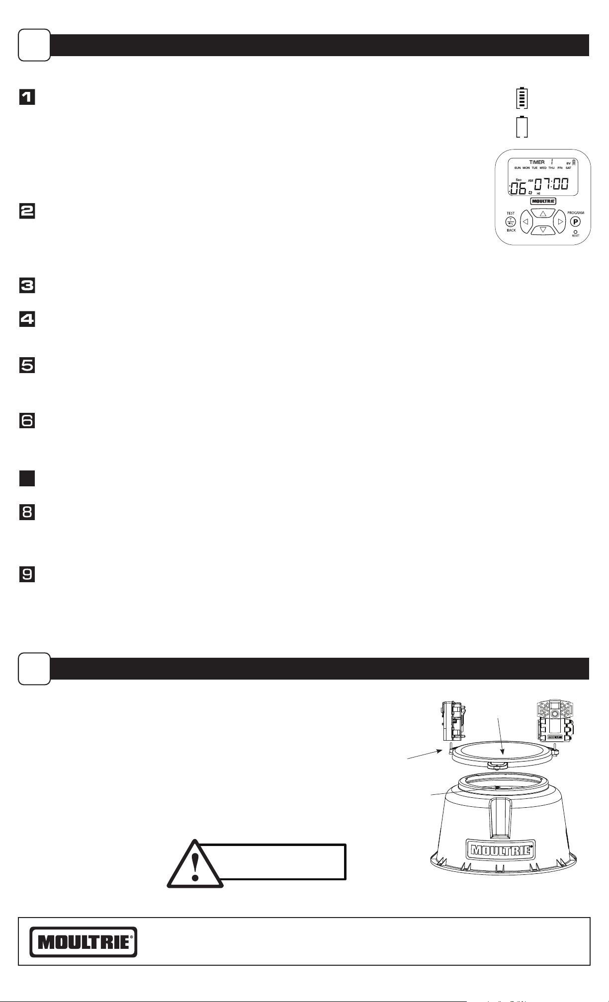
INSTALL BATTERY: Open Kit by removing wingnut located on the bottom and remove outer case. Install a 6-Volt Alkaline
(ex. Energizer™) or Moultrie rechargeable battery (MFHP12406) by attaching the Red Alligator Clip to the positive terminal (+)
and the Black Alligator Clip to the negative (-) terminal, making sure that the leads do not touch. Note: Make sure the
rubber protectors are around the gator clips after installation onto the battery. This helps protect the gator clips
from touching which can cause damage. We recommend using our Moultrie MFHP12406 6V 5ah battery.
CAUTION: DO NOT REVERSE POLARITY OF THE BATTERY LEADS. DO NOT LET THE BATTERY LEADS COME IN CONTACT WITH ONE ANOTHER WHILE CONNECTED
TO
A BATTERY. THIS CAN CAUSE PERSONAL INJURY OR PROPERTY DAMAGE. IN NO EVENT SHALL PRADCO BE LIABLE FOR ANY DIRECT, INDIRECT, PUNITIVE,
INCIDENTAL,
SPECIAL CONSEQUENTIAL DAMAGES, TO PROPERTY OR LIFE, WHATSOEVER ARISING OUT OF OR CONNECTED WITH THE USE OR MISUSE OF
THIS PRODUCT. YOUR USE OF THIS PRODUCT IS AT YOUR OWN RISK.
SET CURRENT TIME: Press the PROGRAM button and SET CURRENT TIME will appear. Press UP or DOWN to set the
hour, then press RIGHT to go to the minutes. Press UP or DOWN to set the minutes. Press the BACK button to return
to the Main Menu , or press PROGRAM to proceed through the settings.
NOTE: The timer is capable up to 10 feed times, each 1-60 seconds each, and each can operate on
any day of the week where each day can be toggled ON/OFF.
SET CURRENT DAY: Press the PROGRAM button until the Set Current Day screen appears. Press LEFT or RIGHT to select the
current day. Press BACK to return to the Main Menu, or press PROGRAM to proceed through the settings.
SET EST. FEED REMAINING: Press the PROGRAM button until the Est. Feed Remaining screen appears. Press UP or DOWN
to select the amount of feed you have in the feeder. Press BACK to return to the Main Menu, or press PROGRAM to proceed
through the settings.
SET FEED TIME: Press the PROGRAM button until the desired Feed Timer appears at the top of the screen. Press the DOWN
button until the feed time is ashing. Press PROGRAM to enter edit mode. Press UP or DOWN to set the hour. Press the
RIGHT button to go over to the minutes. Press UP or DOWN to set the minutes. Press PROGRAM or BACK to return to the
Feed Timer. The factory settings include two feeder times 7am and 6pm, each for 6 seconds.
SET DAYS OF THE WEEK: After setting the feed time, press UP so the days of the week start ashing. Press PROGRAM
to
enter edit mode. By default all days should be enabled. Press LEFT or RIGHT to highlight the desired day. Press DOWN to
disable the selected day. Press UP to re-enable the selected day. Once all desired days are selected, press PROGRAM or
BACK to return to the Feed Timer.
SET RUN DURATION: Press DOWN and LEFT until the RUN DURATION seconds are ashing. Press PROGRAM to enter edit
mode. Press UP or DOWN to set desired feed duration. Press PROGRAM or BACK to return to the Feed Timer.
SET MOTOR SPEED: Press UP or DOWN until the motor speed setting is ashing at the bottom of the screen. Press PROGRAM
to enter edit mode. Press RIGHT or LEFT to select the desired motor setting. Press PROGRAM or BACK to return to the Feed Timer.
When the Feed Timer is blinking at the top of the screen, press PROGRAM or RIGHT to advance to the next feed timer.
Repeat for all required feed times.
TEST FEEDER: Press the BACK button to reach the Main Menu. Press the TEST button to enter the Test Mode. The Test
Duration will appear (this will be the same as the duration as Feed Timer 1). Press UP or DOWN to set the Test Duration.
Press PROGRAM. Press RIGHT or LEFT to select desired motor speed. Press PROGRAM to perform test.
After a 5 second countdown, the test will commence.
Full Battery
Empty Battery
77
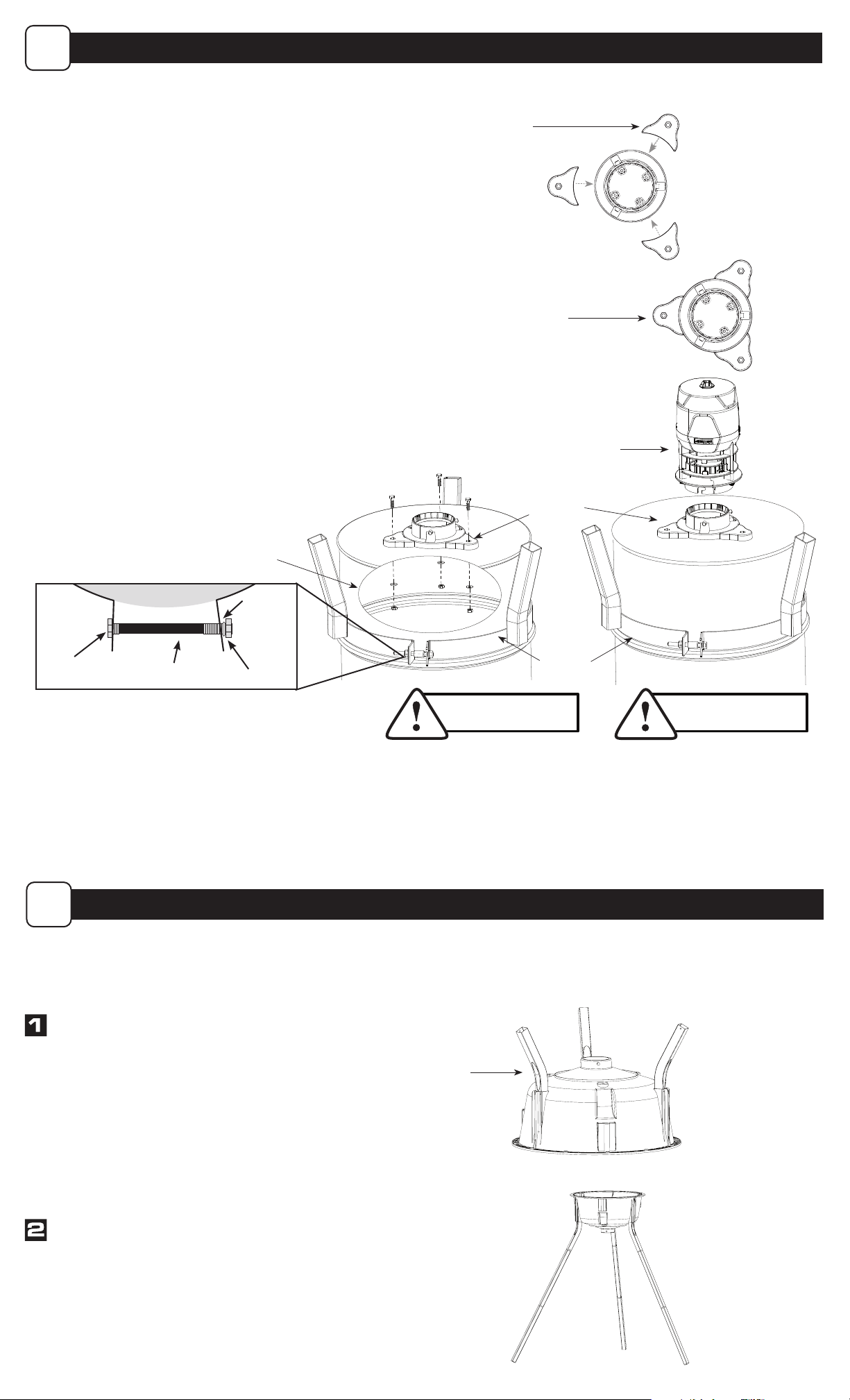
Lid
DO NOT EXCEED
200 LBS OF FEED
Lid Stop
1/4”-20 x 1”
Phillips-head
Bolt
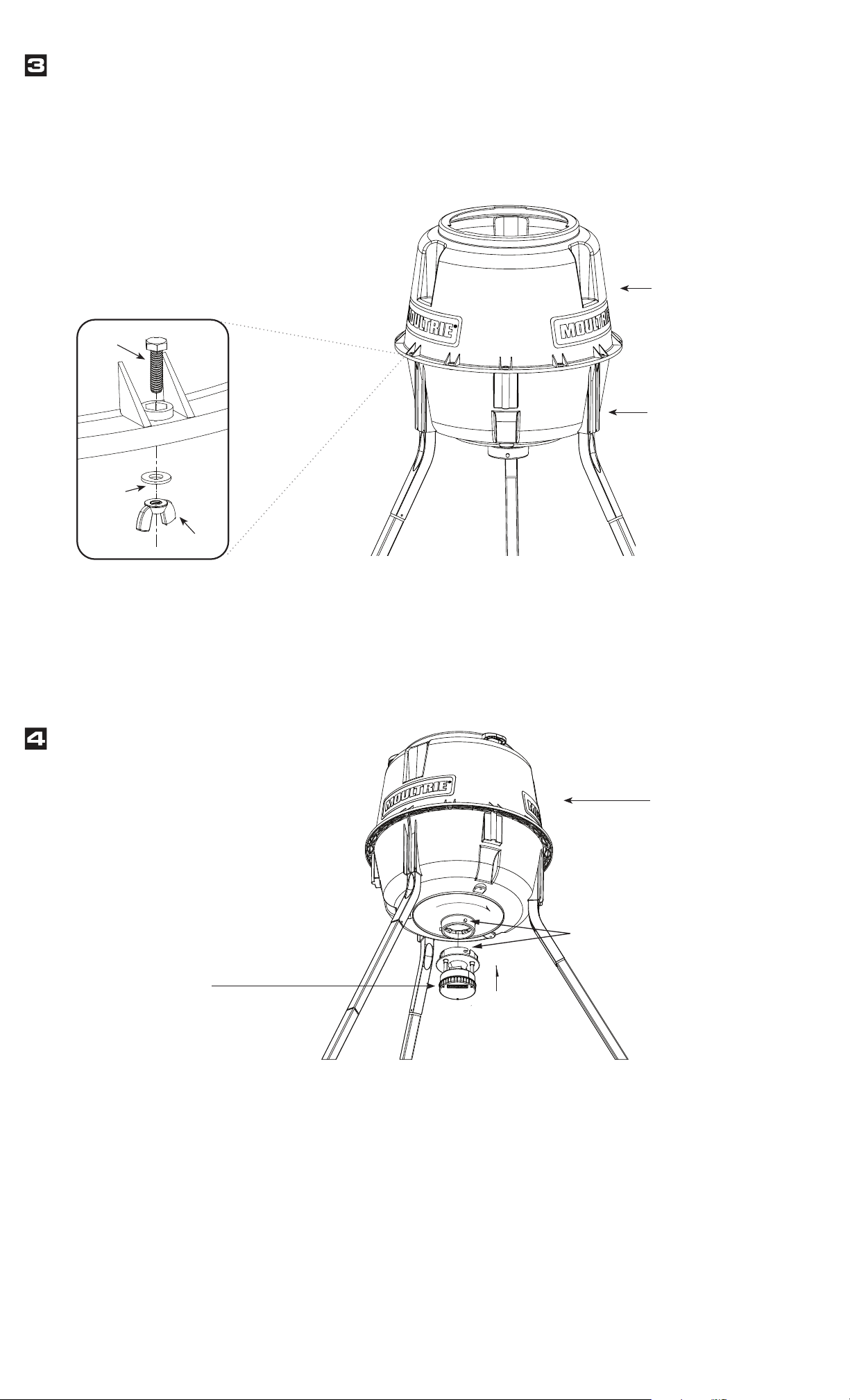
Fill with corn/feed. Do not exceed 200 lbs.
Install lid by aligning handles with notches in hopper top. Twist until
lid rests ush against lid stop.
To install a Moultrie game camera or Feeder Power Panel (sold separately),
thread included 1/4”-20 x 1” Phillips-head bolt upward through hole in
lid handle and tighten bolt. Lid will hold up to 3 devices.
FILLING FEEDER
F