Mountfield IBIZA User manual

IBIZA
Circular and oval swimming pools
INSTALLATION GUIDE
Montageanleitung
für runde und ovale Swimmingpools
IBIZA
Инструкция по монтажу
для круглых и овальных бассейнов
IBIZA
1
IBIZA
Circular and oval swimming pools
INSTALLATION GUIDE
Safety Information
Please read the complete Installation Guide including Safety Guidelines first
and follow them during swimming pool construction and use.
Use appropriate safety devices to prevent uncontrolled access into the pool,
specifically by children under 5 years of age, thereby preventing their
drowning or severe injury.
Non-swimmers and children must be under constant supervision by an experienced person.
Remember that safety guidelines and safety devices cannot substitute personal supervision
by a skilled person, they can only support it.
Read more detailed information starting on page 30.
© 2019 – Mountfield a.s. –05/2019 No. 733B
EN

2
Contents
1 Important comments......................................................................................................................................3
1.1 Swimming pool earthing.........................................................................................................................3
2 Introductory information ...............................................................................................................................3
2.1 Swimming pool parts..............................................................................................................................3
2.2 Swimming pool siting .............................................................................................................................4
2.3 Filter location..........................................................................................................................................4
2.4 Spatial arrangement options ..................................................................................................................4
2.5 Bed preparation......................................................................................................................................5
2.6 Pool liner.................................................................................................................................................5
3 Construction preparation ...............................................................................................................................6
3.1 Pit for a circular swimming pool.............................................................................................................6
3.2 Base slab.................................................................................................................................................6
3.3 Pit for an oval swimming pool................................................................................................................7
4 Swimming pool installation ..........................................................................................................................10
4.1 Circular swimming pool installation .....................................................................................................10
4.2 installation of an oval swimming pool..................................................................................................11
4.3 Steel wall installation............................................................................................................................12
4.4 Processing of the bottom wall edge trims and joining the wall ends with a sliding-in section ...........13
4.5 Preparation of openings for the accessories........................................................................................15
4.6 Laying protective geotextile padding ...................................................................................................19
4.7 Hanging the pool liner and installing the top wall edge trim...............................................................20
4.8 Installing the parts to be built in ..........................................................................................................24
4.9 Complete the technology installation procedures...............................................................................26
5 Dry concrete around the swimming pool.....................................................................................................27
6 Miscellaneous...............................................................................................................................................28
6.1 Water level and skimmer flap ..............................................................................................................28
6.2 Entering the swimming pool.................................................................................................................28
6.3 Advice for using the swimming pool ....................................................................................................29
6.4 Liner repair ...........................................................................................................................................29
6.5 Maintenance.........................................................................................................................................29
6.6 Preparing for the winter season...........................................................................................................30
7 Safety rules ...................................................................................................................................................30
3
1 Important comments
Read all sections of this document
carefully and strictly follow all
instructions.
Illustrations and pictures in this document are partly
symbolic and typical presentations to give the reader
a general idea of the topics described.
Inspect the package(s) delivered before starting the
assembly to make sure that all parts of the swimming
pool have been provided. Inspect all parts to detect
any defect. Mountfield shall not be liable for any
damage arising during the shipment if claimed after
assembling the parts. Mountfield reserves the right to
make changes resulting from technological progress.
Make sure that the steel wall will come in
contact with suitable building materials
only.
For instance, if you intend to use silicone, make
sure that this material contains no acids that may
damage the steel wall's protective coating and
potentially result in corrosion. It may be
necessary to determine if the materials planned
are appropriate with respect to the intended use.
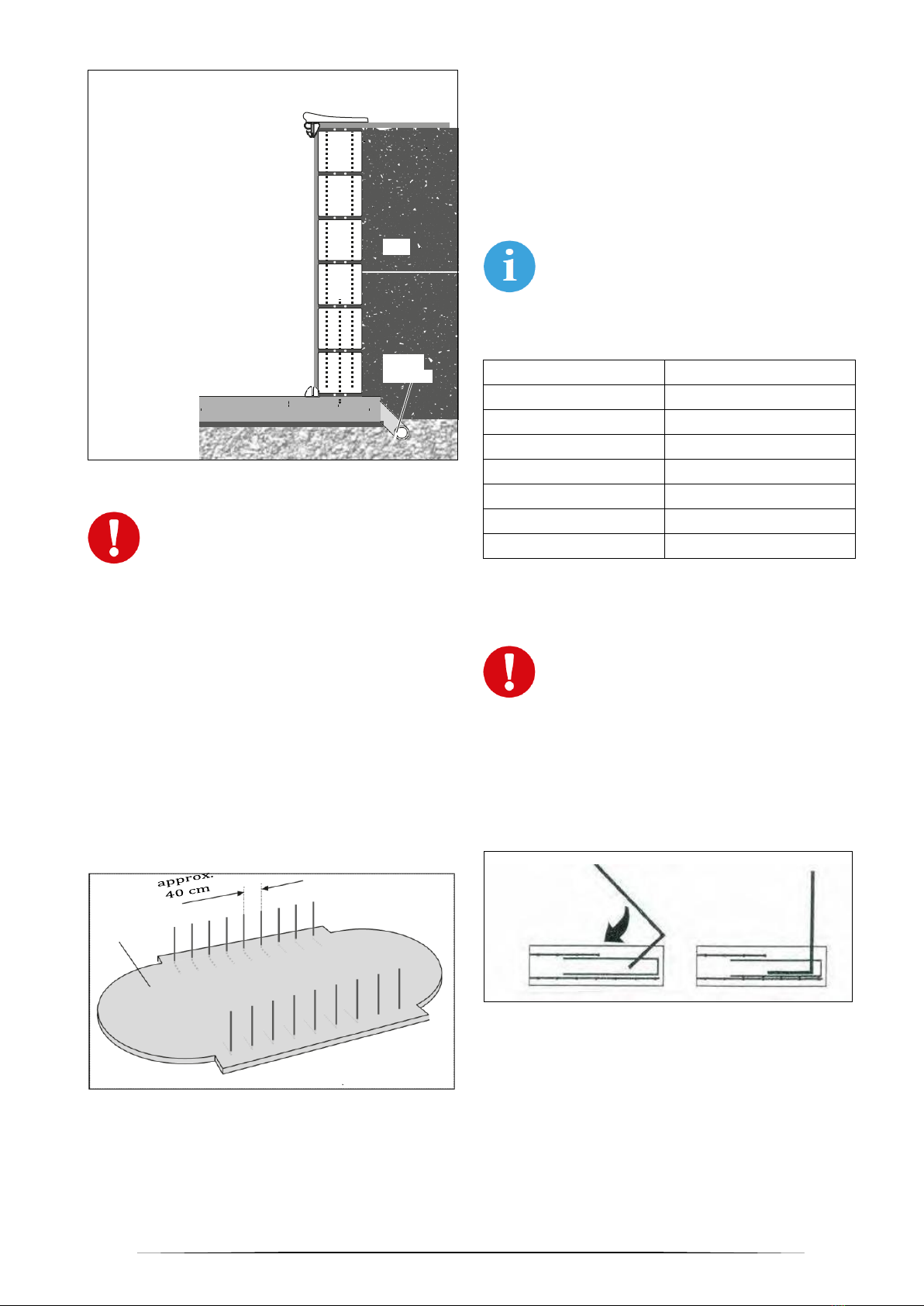
1.1 Swimming pool earthing
The swimming pool wall and all large-area metallic
parts must be bonded in compliance with applicable
local regulations. This is a job for a qualified
electrician.
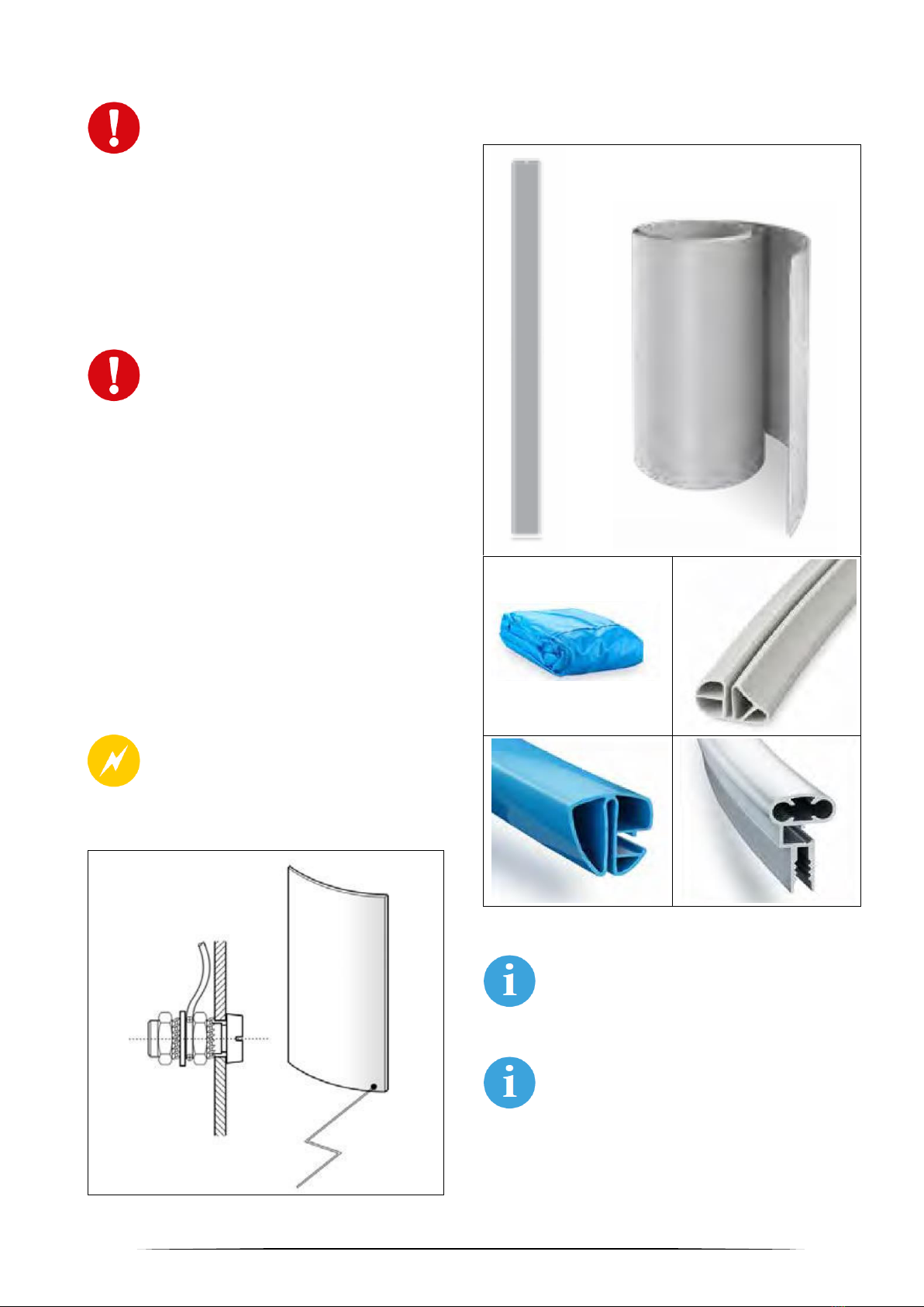
For this, the steel wall may be drilled through in the
lower part (and then treated with a zinc spray or a
plastic paint) and the earthing cable connected to a
metallic bolt (Fig. 1). The cable is routed from the bolt
to an earthing pole.
Warning: All electrician's work must be
done by a qualified company and in
compliance with applicable electrical
standards (such as DIN VDE 0100 Part
702).
Fig. 1
2 Introductory information
2.1 Swimming pool parts
Fig. 2
The picture above does not show all parts
delivered. The design and colour of the
parts delivered may differ from what is
shown.
The illustrations and pictures reproduced
here may differ from the product actually
delivered. They are only meant to help the
reader understand the text herein.
The manufacturer reserves the right to
make changes without prior notice.
Sliding-in section
for joining the
vertical steel wall
edges
Steel wall
Pool liner
Aluminium top
wall rail
Bottom wall edge
trim
Top wall edge
trim
4
2.2 Swimming pool siting
The swimming pool should stand on a sunny place if
available, not very far from the house. The skimmer
(collecting foreign matter from the pool water surface)
should be located downwind, so any foreign mater
floating on the surface is pushed by wind to the
skimmer. What is more important, however, is that
the skimmer should be installed on the side that is
closer to the filter.
2.3 Filter location
Install the filter system as close to the swimming pool
as possible. Preferably the suction piping (skimmer
piping) should be shorter that the return piping
(nozzle piping).
The filter system can be installed in a shaft, in the
house, in a garden house, etc. If installation in the
house and in a shaft is selected, the floor must be
provided with a drain (sink) in case of water leak.
Water from the back flushing must also be drained,
roughly 200 litres every 1-2 weeks. This can be done
by means of fixed piping or a hose ending in a drain.
If the filter system lies higher that the water level, a
return valve must be installed on the suction side,
that is, on the skimmer piping. This must be installed
1–1.5 m far from the sand filter system and must be
accessible at all times.
The planned water heating method is also an
important factor when selecting the place for the filter
system. If the swimming pool is to be heated by a
dedicated solar system, the filter system should be
installed as close to the solar absorber as feasible.
Even if an air-water heat pump is planned for outdoor
installation, the filter system should preferably also be
installed in the garden. However, if the heat
exchanger is connected to the central heating
system, installation of the filter in the house is virtually
inevitable.
2.4 Spatial arrangement options
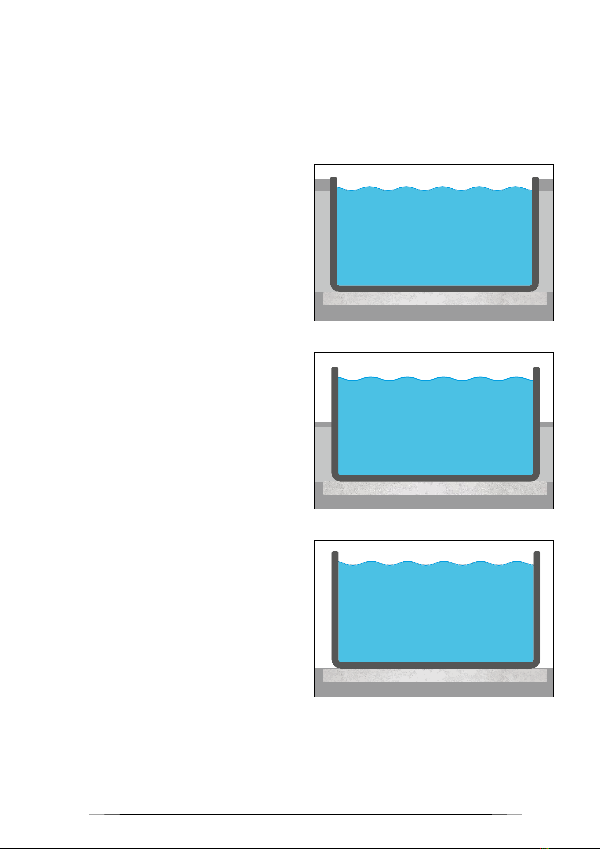
2.4.1 Spatial arrangement options –circular
swimming pool
Three different options exist for the installation of a
circular swimming pool irrespective of its depth and
size:
Inground swimming pool
Fig. 3
Semi-inground swimming pool
Fig. 4
Above-ground freestanding swimming pool
Fig. 5
Swimming pools 150 cm deep must always be at
least 60 cm sunk in the ground.
For such swimming pools and for inground and semi-
inground swimming pools the area around the
inground part must always be backfilled with lean
concrete.

5
2.4.2 Spatial arrangement options –oval
swimming pool
Oval swimming pools cannot be installed arbitrarily
and their inground part must encompass least 2/3 of
their total height. The installation site must be
provided with a concrete base slab and with retaining
walls on the long sides, which must be joined with the
base slab by means of steel reinforcement.
Once the construction is complete, the area around
the front sides to the oval swimming pool must be
backfilled with lean concrete or bricked in.
Fig. 6
1) The skimmer/nozzle side
2) Pool stairs
3) Pool lights shedding light away from the
installation site (if any)
4) Pool liner
5) Steel wall
6) Construction sheets + polystyrene
7) Steel wall joining section
8) Retaining wall (reinforced)
9) Reinforced concrete base slab
10) Water draining
11) Gravel (subbase)
2.5 Bed preparation
The swimming pool ground must meet appropriate
static strength requirements and must be solid and
compact. Any inclined surfaces must be eliminated.
Never create any backfill on the slopes! Any slopes
must be supported by retaining walls. Never support
a slope by the swimming pool wall!
The ground for the swimming pool must be natural, it
should not consist of infilling. Any filled-in earth
should be compacted so that the swimming pool
should not sink or else more efforts must be made
when constructing the foundations. If in doubt,
contact a specialized civil engineer or a structural
engineer.
Important when installing the pool into
earth: The swimming pool must not get
into a groundwater area! If groundwater
is encountered during the excavation
work, a civil engineer-specialist must be
contacted and an acceptable solution
must be found!
A reinforced concrete base slab must be used. A
gravel layer is normally used as the subbase. Water
draining piping is generally recommended for
inground swimming pools.
2.6 Pool liner
The pool liner is made of a thermoplastic material.
So, the swimming pool must be mounted at outdoor
temperatures between +15°C and +25°C. Do not
install the liner under strong sunlight, it is better to
wait till the evening.
Because of its material properties, if exposed to low
temperatures, the liner may by about 50 cm shorter
than as required for the swimming pool.
Prevent the swimming pool liner from
getting in contact with any material that
is incompatible with PVC. To this end the
use of protective geotextile padding is
recommended.
6
3 Construction preparation
3.1 Pit for a circular swimming pool
When digging out the ditch for a (nearly)
inground swimming pool, a working area
50 cm wide or wider must be left for later
installation of the swimming pool
structure parts and their connection to
the piping.
If the inground height does not exceed one-half of the
total pool height and the piping should not be buried,
an area 20–30 cm wide will be sufficient.
Remember that the lean concrete backfilling of the
area immediately after the steel walls must be 15–30
cm thick. More information can be found on page 27.
Recommended pit dimensions:
Swimming pool
Pit dimensions
Width x length [m]
Width x length [m]
3.60 diam.
4.60 diam.
4.00 diam.
5.00 diam.
4.60 diam.
5.60 diam.
5.00 diam.
6.00 diam.
6.00 diam.
7.00 diam.
For the sake of simplicity the pit has normally a
rectangular shape, although it can, of course, also be
circular or oval as appropriate, with the required
dimension margins.
The dug-out depth depends on the base slab and
gravel layer thickness as well as on the depth and
height of the swimming pool.
The rule of thumb is:
The base slab is typically 15 cm thick, the gravel
layer is typically about 5 cm thick (the precise
thickness will be determined by the installing
company depending on the bedrock).
Important: If the filter system is not
located immediately at the swimming
pool and the piping is planned to be
buried, then the trenches for the piping
must be excavated simultaneously with
the pit for the pool.
The trenches for the piping must be excavated
simultaneously with the pool pit. They should be
approximately 40–50 cm wide and about 80 cm deep.
If the possibility to completely drain the piping before
the winter season exists, the pipes can be laid higher,
inclined downwards to the (lowest-lying) draining
point.
For this we recommend preparing a large (160 mm in
diameter or larger) plastic or similar pipe at the
appropriate site.
If required, trenches can also be excavated for piping
from the filter system to a solar heating system and
for power supply cables.
3.2 Base slab
Once the pit is dug out and a water draining system
prepared, the concrete base slab (C16/20) reinforced
with a Q 188A construction steel mesh is fabricated.
The recommended base slab thickness is about 15
cm: the actual thickness (and the gravel layer
thickness) should be specified by a specialized civil
engineer.
The base slab should be laid precisely
horizontally, with no gradient, and its
edges should overreach the swimming
pool edges by some 10 cm.
Once again, the base slab can be rectangular or
circular/oval (copying the swimming pool contours).
Warning: Respect the concrete setting
time (typically 28 days). Only a civil
engineer-specialist may decide (on
his/her own responsibility) that this time
can be shortened .
Gravel layer thickness
+concrete slab thickness
+ swimming pool (inground) depth
= digging depth

7
3.3 Pit for an oval swimming pool
3.3.1 Ground plan and size: swimming pool and
retaining wall
Fig. 7
Swimming pool
Retaining wall
Width x
length [m]
A [m]
R [m]
MB [m]
M [m]
3.20 × 5.25
2.05
1.60
3.24
2.25
3.20 × 6.00
2.80
1.60
3.24
3.00
3.50 × 7.00
3.50
1.75
3.54
3.70
4.16 × 8.00
3.84
2.08
4.20
4.04
4.16 × 10.00
5.84
2.08
4.20
6.04
6.00 × 12.00
6.00
3.00
6.04
6.20
3.3.2 The pit
A margin of a minimum of 50 cm must
remain in the rounded swimming pool
segment where the skimmer and nozzles
are to be mounted, to allow the parts to be
built in and interconnected with the piping at
a later stage.
Margins of 30 cm are sufficient on the opposite side
and on the longitudinal sides.
Remember that the space immediately behind the
steel walls (except for the retaining wall segments)
must be backfilled with lean concrete at a 15–30 cm
thickness of bricked in.
Recommended pit dimensions:
Swimming pool
Pit dimensions
Width x length [m]
Width x length [m]
3.20 × 5.25
4.30 × 6.25
3.20 × 6.00
4.30 × 7.00
3.50 × 7.00
4.60 × 8.00
4.16 × 8.00
5.25 × 9.00
4.16 × 10.00
5.25 × 11.00
6.00 × 12.00
7.10 × 13.00
For the sake of simplicity the pit has normally a
rectangular shape, although, of course, it can also be
circular or oval as appropriate, with the required
dimension margins.
The dug-out depth depends on the base slab and
gravel layer thickness as well as on the swimming
pool depth.
The rule of thumb is:
The base slab is typically 15 cm thick, the gravel
layer is typically about 5 cm thick (the precise
thickness will be determined by the installing
company depending on the bedrock).
The above-ground swimming pool height must not
exceed 1/3 of the total swimming pool height.
Typically the swimming pool's top edge is made flush
with the ground and then covered with a rim.
L = Swimming pool length
A
= Swimming pool straight
segment length
MB
= Retaining wall distance
(polystyrene not included)
B = Swimming pool width
R = Swimming pool radius
M = Retaining wall length
Swimming pool contours
L
A
M
MB
B
Gravel layer thickness
+concrete slab thickness
+ swimming pool depth
= digging depth
8
Fig. 8
Important: If the filter system is not
located immediately at the swimming
pool, trenches for the piping must be
excavated simultaneously. The trenches
should be about 40–50 cm wide and
about 100 cm deep. If the option to
completely drain the piping before the
winter season exists, the pipes can be
laid higher, inclined downwards to the
(lowest-lying) draining point.
For this we recommend preparing a large (160 mm in
diameter or larger) plastic or similar pipe at the
appropriate site.
If required, trenches can also be excavated for piping
from the filter system to a solar heating system and
for power supply cables.
3.3.2 Base slab
Fig. 9
Once the earth excavating and water draining (after
gravel layer laying if necessary) operations have
been completed, the concrete base slab (C16/20)
with reinforcement (Q188A construction steel mesh)
is fabricated. The recommended base slab thickness
is about 15 cm: the actual thickness (and the gravel
layer thickness) should be determined by a
specialized civil engineer.
The base slab should be laid precisely
horizontally, with no gradient, and its edges
should overreach the swimming pool edges
by some 10 cm.
Base slab dimensions
Swimming pool
Base slab (minimum)
Width x length [m]
Width x length [m]
3.20 × 5.25
3.90 × 5.50
3.20 × 6.00
3.90 × 6.25
3.50 × 7.00
4.20 × 7.25
4.16 × 8.00
4.86 × 8.25
4.16 × 10.00
4.86 × 10.25
6.00 × 12.00
6.70 × 12.25
Once again, the base slab can be rectangular or
circular/oval (copying the swimming pool shape).
Important: Embedding the steel
reinforcement immediately into the wet
base slab is recommended. The
reinforcement consists of 8mm
construction steel bars with bends, laid
at a spacing of approximately 25 x 50 cm.
Best take one of the hollow blocks to be used for the
retaining wall and imprint the patterns of the later wall
into the wet concrete. Put a bent steel rebar centrally
into each of the now visible internal chambers of the
imprints (Fig. 10).
Fig. 10
Base slab
Gravel layer
Water
draining
Pit
Soil
Wall
Ground level
Swimming pool rim
Mortar / adhesive for tiles
Base slab
Iron rebars
(diam. 8 mm, 25 × 50
cm)

9
3.3.3 Building the retaining walls
Once the base slab can be walked on, the two side
retaining walls should be built. Fill each row of hollow
blocks with concrete (C16/20) and reinforce both
vertically and horizontally with construction steel
rebars (8 mm diam.). While bricklaying, avoid shifting
the joints or disturbing the verticals and straight lines
or the precise parallel orientation of the two retaining
walls.
The retaining wall height depends on the swimming
pool height –see the sketches.
For a safe fastening of the steel wall to the retaining
wall, best make the top 1 to 2 rows by using full
blocks, such as bricks, because (as experience
shows) such blocks will hold the installation screws
better than hollow bocks do. If fastening into filled
hollow blocks is planned, best use very long screws
that will reach the concrete core.
Warning: Consult a civil engineer-
specialist. Mountfield will take no
responsibility for installation errors or
damage resulting from a poorly
constructed retaining wall!
Fig. 11
Fig. 12
Warning: Respect the concrete setting
time (typically 28 days). Only a civil
engineer-specialist may decide (on
his/her own responsibility) that this time
can be shortened .
The wall height (measured from the top edge of the
base slab) must NOT exceed 115 cm / 145 cm for
swimming pool height 120 cm / 150 cm, respectively,
or the top edge trim cannot be installed properly.
Brick
Polystyrene
board 2 cm thick
Hollow block
24 cm high
Vertical and horizontal
steel rebars
Base slab
Brick
Polystyrene board
2 cm thick
Hollow block
24 cm high
Vertical and horizontal
steel rebars
Base slab
112–115 cm
120 cm
142-145 cm
150 cm
Bushing for
technologies
≥80 mm diam.
Bushing for
technologies
≥80 mm diam.

10
Fix the polystyrene boards 20 mm thick to the internal
side of the retaining walls by using an adhesive for
polystyrene. A 25 mm offset above the base slab
must be left free for the bottom edge trims (Fig. 13).
Fig. 13
1) Polystyrene board
2) Bottom edge trim
3) Base slab
Important: If swimming pool lights are
planned to be installed, openings for this
installation must be made/prepared
during the retaining wall building
process. Follow manufacturer's
instructions.
4 Swimming pool installation
4.1 Circular swimming pool installation
Depending on the swimming pool size, its installation
is a job for 3–4 persons and should be made in
windless conditions. The use of gloves during the
steel wall construction is recommended.
First, draw the swimming pool contour on the ground.
This will immensely facilitate the swimming pool siting
and installation procedures . For this, fasten a string
to a nail driven into the centre of the future pool and
measure the radius (= one-half of the diameter). Use
a piece of chalk or a bricklayer's pencil to mark the
radius measured with the string –see Figs. 14 and15:
The bottom and top wall edge trims are provided. You
will find them inside the coiled steel wall.
Fig. 14
Fig. 15
4.1.1 Installation of the bottom wall edge trims
Combine the bottom edge trim segments (approx. 20
mm wide) into one unit by means of the joining tubes
and put the closed swimming pool contours on the
ground. Proceed by following the ground plan.
Check precisely the dimensions and symmetry.
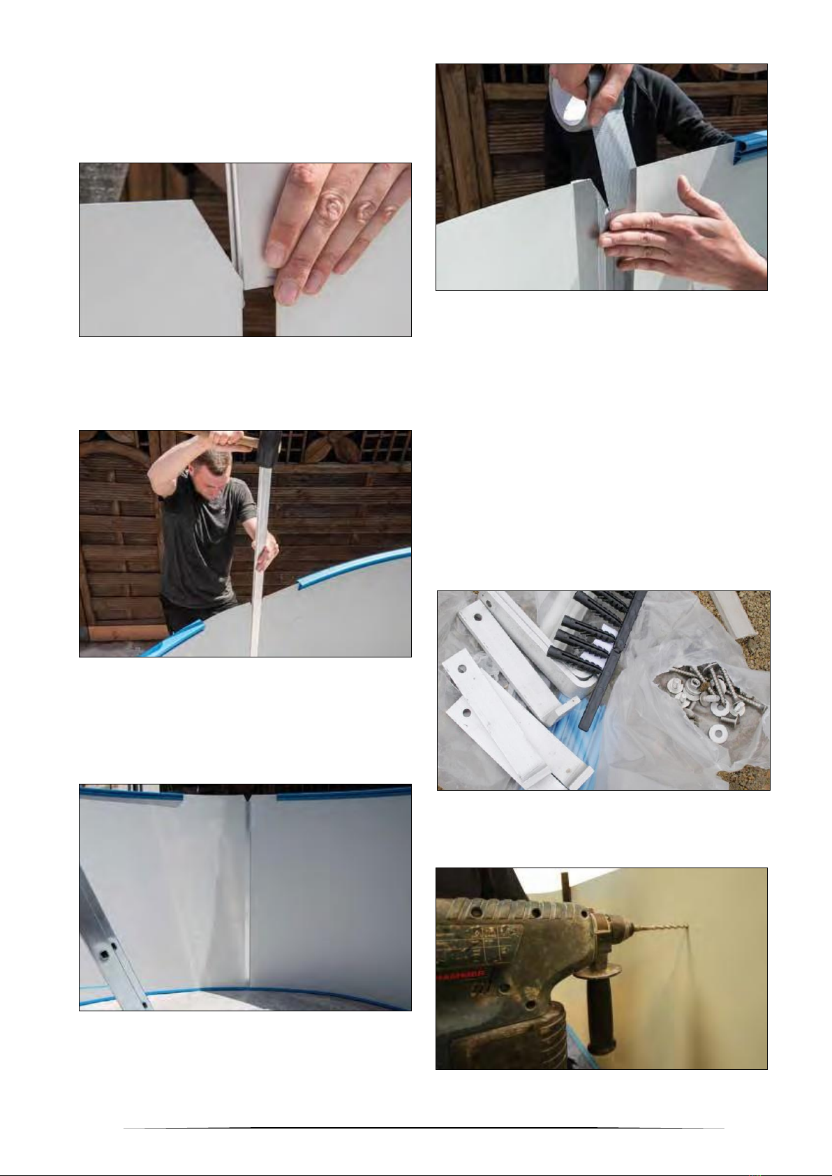
Professional hint for the installation of the
bottom edge trims (and later also the top
edge trims): Combination of the segments
into one unit will be much easier if the pins
are greased.
For this, insert a pin into one segment, grease the still
protruding side (see Fig. 16) and combine the edge
trims (Fig. 17).

11
Professional hint for shortening the bottom
edge trims: First combine all the edge trims
into one and align as appropriate according
to the ground plan. Any overhanging ends
should be shortened only when building the
steel wall because only then the differences
in the dimensions are apparent and can be
trimmed as appropriate.
The precise procedure is shown in Figs. 28-30 on
page 13.
Fig. 16
Fig. 17
Fig. 18
4.2 installation of an oval swimming
pool
First, draw the swimming pool contour on the ground.
The semi-circles of the rounding can be best marked
by means of a string fixed with the nail in the centre
of the future pool. Mark the lines with a bricklayer's
pencil or chalk. The swimming pool dimensions,
including the radius, are shown in Fig. 7 on page 7.
4.2.1 Installation of the bottom edge trims
First slide the straight bottom edge trim segments
(width approx. 20 mm) into one another. Lay the
straight parts of the bottom wall edge trim directly in
front of the brick wall, into the space in the
polystyrene, and centre the edge trims against the
brick wall length. The wall is very slightly longer.
Professional hint for laying the straight edge
trims symmetrically: Measure diagonally the
end points of the edge trims. The
dimensions will be identical if the edge trims
have been laid symmetrically. See
dimension “a” in Fig. 19.
Join the bent bottom edge trim pieces and use them
to fill the rounded segments on the front sides.
Proceed by following the ground plan.
Check precisely the dimensions and symmetry.
Professional hint for shortening the bottom
wall edge trims: First combine all the edge
trims into one and align as appropriate
according to the ground plan. Any
overhanging ends should be shortened only
when building the steel wall because only
then the differences in the dimensions are
apparent and can be trimmed as
appropriate. See section 4.4.
Fig. 19

12
4.3 Steel wall installation
If you want to be able to get into the swimming pool,
you will need swimming pool steps/stairs or a ladder.
Later, when installing the liner, be cautious for the
construction ladder not to damage the liner.
Furthermore, bring the coiled steel wall into the
swimming pool before installing it.
With the assistance of your helpers move the steel
wall roughly to the point where the skimmer (surface
impurity collector) should be installed and put it onto
thick boards and cartons to facilitate its uncoiling (see
Fig. 20). When uncoiling the steel wall, do NOT drag
it over the concrete foundation, it might get damaged.
Fig. 20
The steel wall is coiled inwards in the
factory so the outer side is visible on the
coiled steel wall.
So, uncoil the steel wall in the direction in which it has
been coiled.
In order to prevent injury, wear gloves when uncoiling
and mounting the steel wall and use straps to control
the uncoiling process. (see Fig. 21).
Fig. 21
The recess for the skimmer is normally located at the
beginning of the uncoiling steel wall (approx. 1–2 m
from the front end). If the steel wall is packed in more
than one package, it is shown on the boxes which
steel wall parts (with which recesses for the structure
parts) are included.
Fig. 22
Fig. 23
Uncoil the steel wall and slide it into the edge trims
(see Figs. 22–23). The skimmer recess must be
positioned as required (as close to the filter system
as possible).
The return nozzle is located left of the skimmer
(viewed from outside).
If a joining section is present on one side of the steel
wall, it must be slid out.
Where large swimming pools are concerned, the
steel wall is divided into 2 parts and the joining
procedure using the sliding-in section is performed
twice.

13
Important hint: Some segments of the top
edge trim may be put on for the steel wall to
provisionally keep its shape (see Fig. 24).
Fig. 24
The steel wall of an oval swimming pool may be
provisionally fixed to the retaining walls by using
screw clamps.
Fig. 25
Fig. 26
Always see to it that the steel wall should stand firmly
in the bottom edge trim.
4.4 Processing of the bottom wall edge
trims and joining the wall ends with a
sliding-in section
The gap between the two steel wall ends should be
about 5 mm to enable the sliding-in section to join the
steel wall ends together. This must be taken into
account when shortening the bottom edge trim.
Fig. 27
Shortening the bottom wall edge trim
Uncoil the steel wall and measure any overhang of
the bottom edge trim. Now draw the steel wall by
some 50 cm out of the bottom edge trims and shorten
the bottom edge trim appropriately (remember that a
5mm gap should be left between the steel wall ends
for the sliding-in section –see above).
Important hint: Always shorten the wall edge
trim in the arched segment. If it is shortened
more than 5 cm, then shortening 2 edge
trims is recommended for the sake of arch
symmetry –each arch by one-half of the
total overhang.
Now put the whole steel wall again on and slide the
sliding-in section over (see Figs. 28–30).
Fig. 28
Fig. 29
14
Depending on the swimming pool type the sliding-on
section may have a side bevelled. If this is the case,
put the sliding-in section with the bevelled side
directed inside and upwards. If none of the sides is
bevelled, there is no difference between the
top/bottom sides.
Fig. 30
Facilitate the section installation by moving it slightly
up and down periodically. The use of a rubber
hammer can also be convenient.
Fig. 31
However, if the section is put on incorrectly and/or
driven down with too much force, the steel wall may
get damaged (and the validity of the warranty may be
limited) and the swimming pool stability may be
compromised.
Fig. 32
Fig. 33
Covering the internal sliding-in section surface with
an adhesive tape is recommended in order to protect
the swimming pool liner from damage.
Additional information regarding oval swimming
pools: Steel wall attachment
It is assumed in this explanation that the retaining
wall height is as described on page 9.
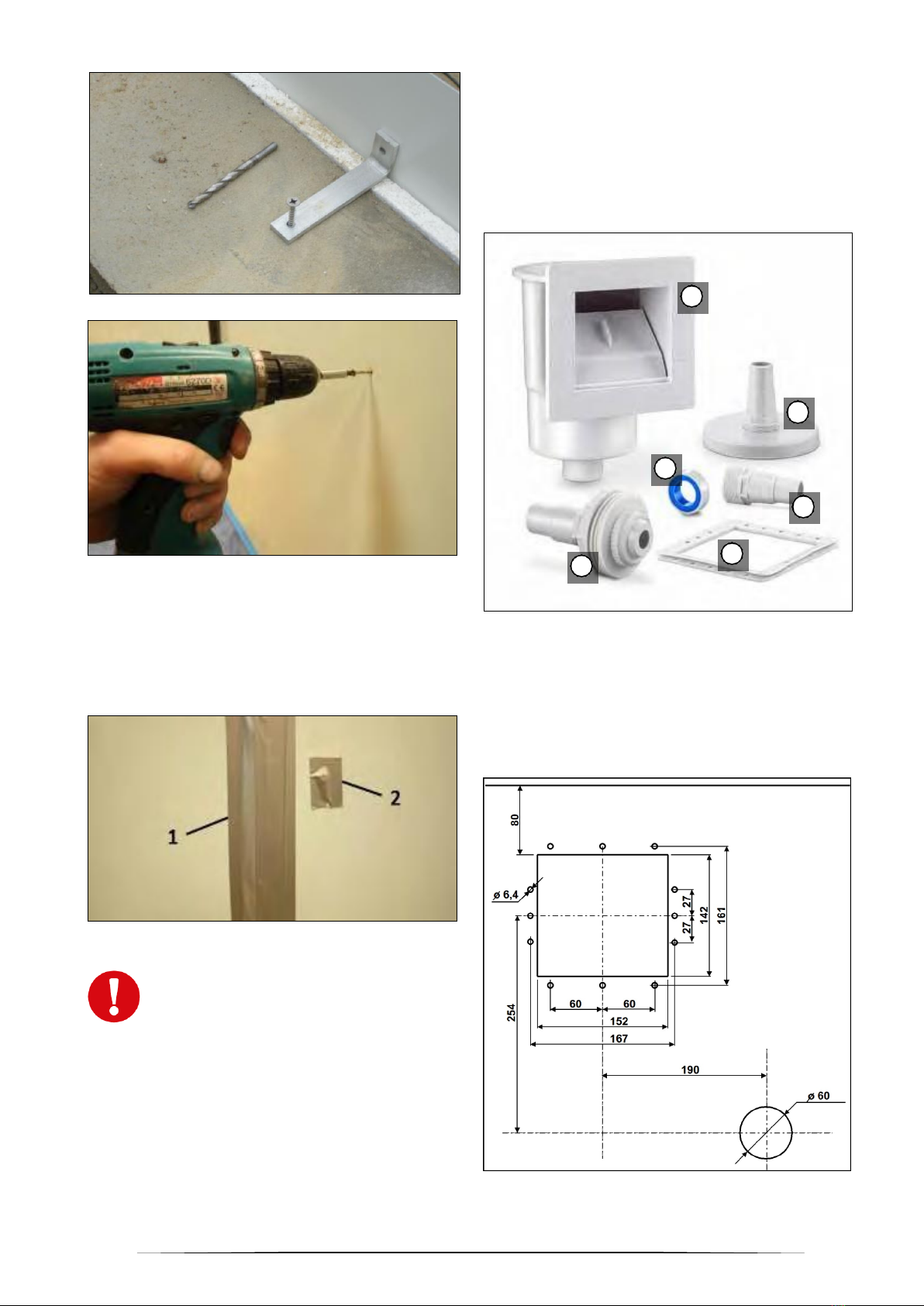
In the area of the retaining walls the steel wall must
be fastened to the retaining wall edge with screws (at
a height of 110 cm or 140 cm from the ground for a
swimming pool 120 cm or 150 cm high, respectively).
The fastening must be in a horizontal line. Use the
screws, wall plugs and try squares provided for this
operation (see Fig. 34).
Fig. 34
Drill the holes in the steel wall. Grind the hole edges
smooth and coat with an anticorrosion paint.
Fig. 35
15
Fig. 36
Fig. 37
In this manner the steel wall is fastened directly onto
the retaining wall.
In order to protect the swimming pool liner, cover the
screw heads with an adhesive tape that will not
damage the PVC (with a packaging tape for
instance).
Fig. 38
Caution: Make sure that the swimming
pool stands perfectly horizontally.
Manufacturer's warranty becomes void
and null it the height difference is larger
than 2 cm. If this is the case, identify the
cause a eliminate the problem, e.g. by
improving the base.
4.5 Preparation of openings for the
accessories
Important: Follow also the accessory manufacturers'
guidelines if attached to the products. If in doubt,
contact your seller.
4.5.1 Skimmer (to collect any foreign matter
from the water surface)
Fig. 39
1) Skimmer body 2) Vacuum plate
3) Teflon tape 4) Hose adaptor
5) Double gasket 6) Nozzle
Openings in the swimming pool steel wall for the
skimmer may be present from the factory. If not, they
must be cut out/drilled.
Fig. 40
6
5
4
3
2
1
16
The sketch above shows the dimensions of a
standard skimmer for attachment by using swimming
pool hoses 38 mm in diameter. If a different skimmer
is to be used, an appropriate template / correct
dimensions and spacing must be used.
We recommend that the cutting edges be ground
smooth and treated with an anticorrosion product or
plastic paint prior to the installation.
Fig. 41
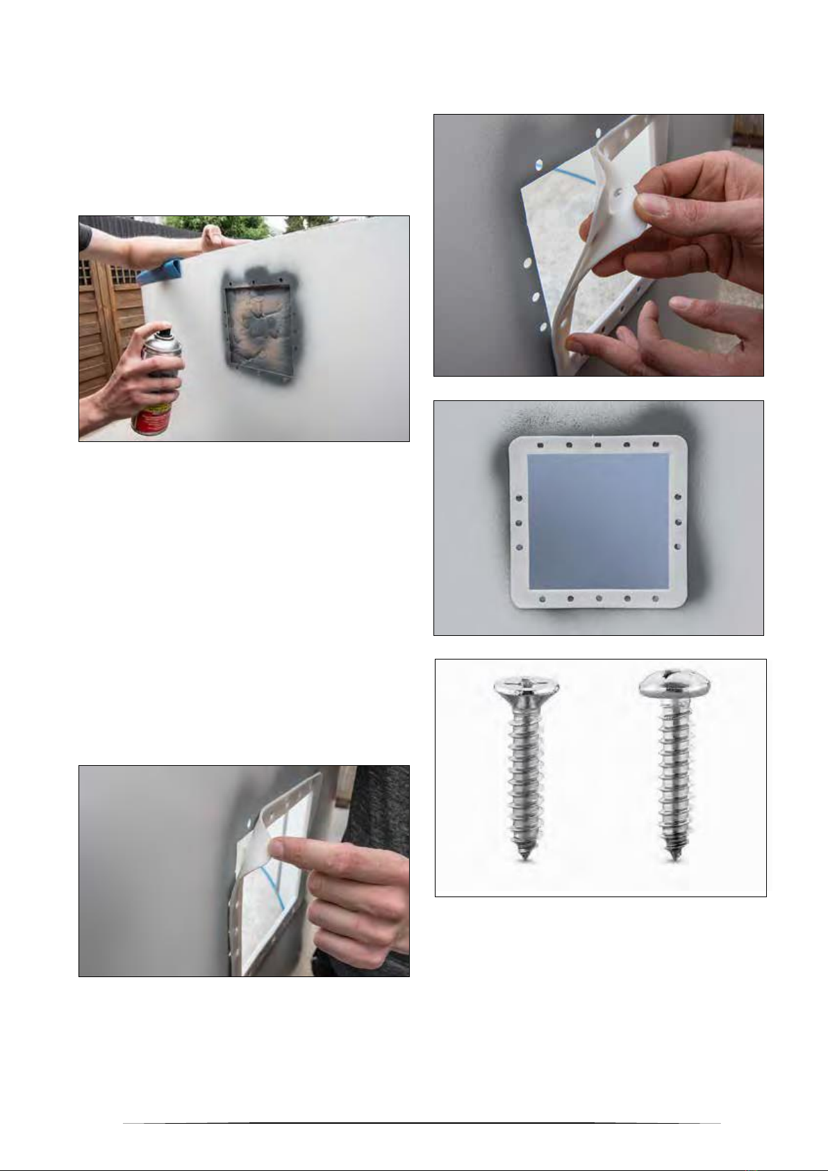
If the piping is to be mounted now, installation of the
skimmer at this stage is recommended. For this, put
the double gasket over the steel wall (see Fig. 43),
hold the skimmer at the opening from the outside and
fix it from the inside with rounded head safety screws
(see Fig. 45). If 2 individual gaskets have been
provided in place of the conventional skimmer double
gasket, they must be put on in order: skimmer body –
gasket –steel wall –gasket (–pool liner –skimmer
flange).
This also applies to the return nozzle gasket(s) (for
more information please read page 24, “Internal parts
installation”).
In certain circumstances it may be necessary to
prepare additional holes in the steel wall (and coat
them with an anticorrosion paint) because not always
are the holes for the screws ready.
Fig. 42
If installing the piping later is feasible, the skimmer
can also be installed later along with the installation
of the liner (see page 20).
Fig. 43
Fig. 44
Fig. 45
Flange screw Safety screw
17
Fig. 46
4.5.2 Return nozzle
The IBIZA swimming pools use normally 1 return
nozzle, located next to the skimmer. Here also the
cutting edges should be treated with anticorrosion
coating.
Fig. 47
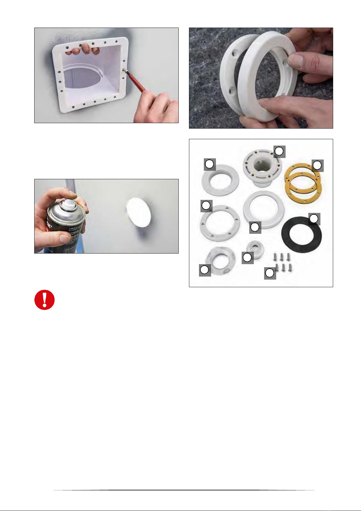
4.5.2.1 Return nozzles for fixed (buried) piping
Important! The nozzle bodies must be
used now, prior to the installation of the
liner, because they are specific high-
quality return nozzles with a flange on
the swimming pool side, which –in
contrast to conventional nozzles –
facilitate appreciably any later liner
replacement.
The flange is needed for the final nozzle
installation. If the nozzle flange cannot be found
promptly, it is probably inserted into the cover .
Compress/bend the cover slightly to separate the
flange and mount the flange (see Fig. 48).
Fig. 48
Fig. 49
1) Adjusting ring 2) Nozzle eye
3) Nozzle body 4) Safety nut
5) Screws 6) Cover
7) Flange 8) Gasket
9) Hole-less gasket
If the return nozzle is completed with an additional
hole-less gasket , this gasket is not used for
swimming pool with steel walls.
5
1
2
6
9
7
8
4
3

18
Fig. 50
Fix one of the self-sticking gaskets onto the nozzle
body flange frame.
Fig. 51
Fig. 52
Put the nozzle body through the opening in the steel
wall from the inside.
Now put on the safety nut on the nozzle thread from
the back (outer swimming pool side) and screw it on.
Fig. 53
Return nozzles with hose couplings 32/38
mm are installed only simultaneously with
the liner (see page 24).

19
4.6 Laying protective geotextile
padding
The swimming pool should be installed in time or it
may collapse. If fast installation is impossible, e.g.
because of bad weather, we recommend that the
padding should not be used for the time being and
the swimming pool wall should be mechanically
secured against any strong wind.
The use of protective geotextile padding or a
protective paulin is recommended to protect the pool
liner against direct contact with the substrate and any
materials in it that might potentially damage the PVC.
Remember, however, that a protective geotextile pad
can only protect but not make for any surface
unevenness.
The substrate must be cleaned thoroughly before
laying the padding.
In some cases the padding has been cut already to
match that of the swimming pool. If the padding was
delivered in rolls, lay it in strips and fix with an
adhesive tape.
Fig. 54
Fig. 55
Cut the padding approximately 10 longer than the
swimming pool dimension and let it overreach around
the swimming pool wall to a height of some 5 cm.
Cuttings can be used for minor side areas. Draw the
overhanging edges over the bottom wall edge trims
and fix to the steel wall with an adhesive tape.
Fig. 56
Fig. 57
Smooth the padding and join the adjacent strip edges
together also with an adhesive tape.
Table of contents
Languages:
Popular Swimming Pool manuals by other brands

Endless Pools
Endless Pools FASTLANE PRO owner's manual

Doughboy
Doughboy CENTURY Assembly instructions

Outside Living Industries
Outside Living Industries ubbink Ocea 355x550 - H120 cm Note of assembly

Bestway
Bestway FAST SET 257002000451 quick start guide

Bestway
Bestway Hydrium 56586 owner's manual

GRE
GRE PEOV9159 instructions


