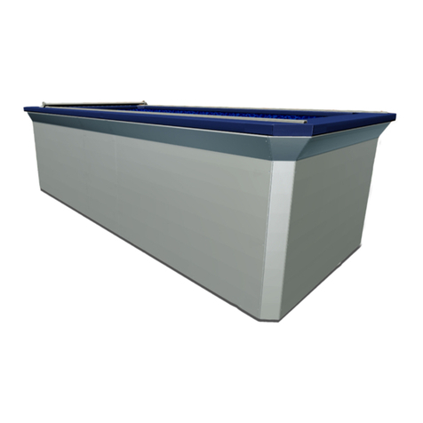
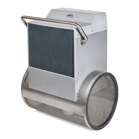
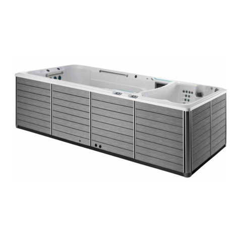
Endless Pools FASTLANE PRO User manual

FASTLANE®PRO
By Endless Pools®
OWNER’S MANUAL

Fastlane®Pro Swim Unit Installation
IMPORTANT SAFETY INSTRUCTIONS
CONSIGNES DE SÉCURITÉ IMPORTANTES
READ, FOLLOW, AND UNDERSTAND
ALL INSTRUCTIONS AND WARNINGS
LIRE, SUIVRE ET COMPRENDRE TOUTES LES INSTRUCTIONS
Manufacturers Safety Instructions
DANGER: BEFORE INSTALLING OR USING THIS PRODUCT, READ, FOLLOW, AND UNDERSTAND
ALL SAFETY INFORMATION. FAILURE TO DO SO CAN RESULT IN DAMAGE, INJURY,
OR DEATH.
DANGER: SERIOUS BODILY INJURY OR DEATH CAN RESULT IF THIS PRODUCT IS NOT
INSTALLED OR USED CORRECTLY.
WARNING: This unit should be installed only per the manufacturer’s instructions.
WARNING: This product must be installed in accordance with any applicable state and local code.
Consult the local building and health code for more information.
WARNING: Before each use, examine the unit for damage or signs of wear. Do not use the product if
found in this condition. Contact Endless Pools Customer Service.
WARNING: Never operate the unit without reading and completely understanding the results of any
operational change you request from the controller.
WARNING: Never use this product alone.
WARNING: Keep all breakables, especially glass, away from this product.
WARNING: Never insert any objects into any openings.
WARNING: Wear appropriate hearing and eye protection while installing this product.
WARNING: Consult a physician before using this product. Stop exercising if you feel pain or tightness
in your chest, become short of breath, or feel faint. Contact your doctor before using this
product again.
WARNING: The appliance is not to be used by persons (including children) with reduced physical, sen-
sory or mental capabilities, or lack of experience and knowledge, unless they have been
given supervision or instruction.
1

Fastlane®Pro Swim Unit Installation Fastlane®Pro Swim Unit Installation
Other Important Safety Instructions
WARNING: To reduce the risk of injury, do not permit children to use this product unless they are closely
supervised at all times.
AVERTISSEMENT: Pour réduire le risque de blessure, ne permettez pas aux enfants d’utiliser ce produit à moins
qu’ils ne soient surveillés de près en tout temps.
WARNING: To reduce the risk of injury. AVERTISSEMENT: Pour réduire le risque de blessure:
a) The water in a spa should never exceed 104 °F (40 °C). Water temperatures between
100 °F (38 °C) and 104 °F (40 °C) are considered safe for a healthy adult. Lower water
temperatures are recommended for young children and when spa use exceeds 10 minutes.
L’eau dans un spa ne doit jamais dépasser 40 °C (104 °F). Les températures de l’eau
comprises entre 38 °C (100 °F) et 40 °C (104 °F) sont considérées comme sûres pour un
adulte en bonne santé. Des températures d’eau plus basses sont recommandées pour les
jeunes enfants et lorsque l’utilisation du spa dépasse 10 minutes.
b) Since excessive water temperatures have a high potential for causing fetal damage during
the early months of pregnancy, pregnant or possibly pregnant women should limit spa water
temperatures to 100 °F (38 °C). Étant donné que les températures excessives de l’eau ont
un potentiel élevé de causer des dommages au fœtus pendant les premiers mois de la gros-
sesse, les femmes enceintes ou éventuellement enceintes devraient limiter la température de
l’eau du spa à 38 °C (100 °F).
c) Before entering a spa, the user should measure the water temperature since the tolerance
of water temperature-regulating devices varies. Avant d’entrer dans un spa, l’utilisateur
doit mesurer la température de l’eau car la tolérance des dispositifs de régulation de la
température de l’eau varie.
d) The use of alcohol, drugs, or medication before or during spa use may lead to uncon-
sciousness with the possibility of drowning. La consommation d’alcool, de drogues ou de
médicaments avant ou pendant l’utilisation du spa peut entraîner une perte de conscience
avec possibilité de noyade.
e) Obese persons and persons with a history of heart disease, low or high blood pressure,
circulatory system problems, or diabetes should consult a physician before using a spa. Les
personnes obèses et les personnes ayant des antécédents de maladie cardiaque, d’hypo-
tension ou d’hypertension artérielle, des problèmes de système circulatoire ou de diabète
devraient consulter un médecin avant d’utiliser un spa.
f) Persons using medication should consult a physician before using a spa since some
medication may induce drowsiness while other medication may affect heart rate, blood
pressure, and circulation. Les personnes qui prennent des médicaments devraient consulter
un médecin avant d’utiliser un spa, car certains médicaments peuvent provoquer de la
somnolence tandis que d’autres médicaments peuvent affecter la fréquence cardiaque, la
pression artérielle et la circulation.
DANGER: RISK OF INJURY: The suction fittings in this spa are sized to match the specific water flow
created by the pump. Should the need arise to replace the suction fittings or the pump, be
sure that the flow rates are compatible. Never operate spa if the suction fittings are broken or
missing. Never replace a suction fitting with one rated less than the flow rate marked on the
original suction fitting.
DANGER: RISQUE DE BLESSURE: Les raccords d’aspiration de ce spa sont dimensionnés pour corre-
spondre au débit d’eau spécifique créé par la pompe. En cas de besoin de remplacement des
raccords d’aspiration ou de la pompe, assurez-vous que les débits sont compatibles. N’utili-
sez jamais le spa si les raccords d’aspiration sont cassés ou manquants. Ne remplacez jamais
un raccord d’aspiration par un autre de moins que le débit indiqué sur le raccord d’aspiration
d’origine.
2
Fastlane®Pro Swim Unit Installation
DANGER: RISK OF ACCIDENTAL DROWNING: Extreme caution must be exercised to prevent
unauthorized access by children. To avoid accidents, ensure that children cannot use this spa
unless they are supervised at all times.
DANGER: RISQUE DE NOYADE ACCIDENTELLE: Une extrême prudence doit être exercée pour
empêcher tout accès non autorisé aux enfants. Pour éviter les accidents, assurez-vous que les
enfants ne peuvent pas utiliser ce spa à moins qu’ils ne soient surveillés en tout temps.
DANGER: RISK OF ELECTRIC SHOCK: Install at least 5 feet (1,5 m) from all metal surfaces. As an al-
ternative, a spa may be installed within 5 feet (1,5 m) of metal surfaces if each metal surface
is permanently connected by a minimum 8 AWG (8,4 mm2) solid copper conductor to the
wire connector on the terminal box that is provided for this purpose.
DANGER: RISQUE DE CHOC ÉLECTRIQUE: Installez à au moins 1,5 m (5 pieds) de toutes les sur-
faces métalliques. Comme alternative, un spa peut être installé à moins de 1,5 m (5 pieds)
des surfaces métalliques si chaque surface métallique est connectée en permanence par un
conducteur en cuivre massif d’au moins 8,4 mm2 (8 AWG) au connecteur de fil sur la boîte à
bornes qui est fourni à cet effet.
A wire connector is provided on this unit to connect a minimum 8 AWG (8,4 mm2) solid
copper conductor between this unit and any metal equipment, metal enclosures of electrical
equipment, metal water pipe, or conduit within 5 feet (1,5 m) of the unit. Un connecteur de fil
est fourni sur cette unité pour connecter un conducteur en cuivre solide d’au moins 8,4 mm2
(8 AWG) entre cette unité et tout équipement métallique, les boîtiers métalliques de l’équi-
pement électrique, la conduite d’eau métallique ou le conduit à moins de 1,5 m (5 pieds) de
l’unité.
DANGER: RISK OF ELECTRIC SHOCK: Do not permit any electric appliance, such as a light, tele-
phone, radio, or television, within 5 feet (1,5 m) of a spa.
DANGER: RISQUE DE CHOC ÉLECTRIQUE: Ne laissez aucun appareil électrique, comme une
lampe, un téléphone, une radio ou une télévision, à moins de 1,5 m (5 pieds) d’un spa.
WARNING: CHILDREN SHOULD NOT USE SPAS OR HOT TUBS WITHOUT ADULT SUPERVISION.
AVERTISSEMENT: NE PAS LAISSER LES ENFANTS UTILISER UNE CUVE DE RELAXATION SANS SURVEIL-
LANCE.
WARNING: DO NOT USE SPAS OR HOT TUBS UNLESS ALL SUCTION GUARDS ARE INSTALLED TO
PREVENT BODY AND HAIR ENTRAPMENT.
AVERTISSEMENT: POUR ÉVITER QUE LES CHEVEUX OU UNE PARTIE DU CORPS PUISSENT ÊTRE ASPIRÉS,
NE PAS UTILISER UNE CUVE DE RELAXATION SI LES GRILLES DE PRISE D’ASPIRATION NE
SONT PAS TOUTES EN PLACE.
WARNING: PEOPLE USING MEDICATIONS AND/OR HAVING AN ADVERSE MEDICAL HISTORY
SHOULD CONSULT A PHYSICIAN BEFORE USING A SPA OR HOT TUB.
AVERTISSEMENT: LES PERSONNES QUI PRENNENT DES MÉDICAMENTS ET (OU) ONT DES PROBLÈMES
DE SANTÉ DEVRAIENT CONSULTER UN MÉDECIN AVANT D’UTILISER UNE CUVE DE
RELAXATION.
WARNING: PEOPLE WITH INFECTIOUS DISEASES SHOULD NOT USE A SPA OR HOT TUB.
AVERTISSEMENT: LES PERSONNES ATTEINTES DE MALADIES INFECTIEUSES NE DEVRAIENT PAS UTILISER
UNE CUVE DE RELAXATION.
3

Fastlane®Pro Swim Unit Installation Fastlane®Pro Swim Unit Installation
WARNING: TO AVOID INJURY, EXERCISE CARE WHEN ENTERING OR EXITING THE SPA OR HOT
TUB.
AVERTISSEMENT: POUR ÉVITER DES BLESSURES, USER DE PRUDENCE EN ENTRANT DANS UNE CUVE DE
RELAXATION ET EN SORTANT.
WARNING: DO NOT USE DRUGS OR ALCOHOL BEFORE OR DURING THE USE OF A SPA OR HOT
TUB TO AVOID UNCONSCIOUSNESS AND POSSIBLE DROWNING.
AVERTISSEMENT: POUR ÉVITER L’ÉVANOUISSEMENT ET LA NOYADE ÉVENTUELLE, NE PRENDRE NI
DROGUE NI ALCOOL AVANT D’UTILISER UNE CUVE DE RELAXATION NI QUAND ON
S’Y TROUVE.
WARNING: THE USE OF ALCOHOL OR DRUGS CAN GREATLY INCREASE THE RISK OF FATAL HYPER-
THERMIA IN HOT TUBS AND SPAS.
AVERTISSEMENT: LA CONSOMMATION D’ALCOOL OU DE DROGUE AUGMENTE CONSIDÉRABLEMENT
LES RISQUES D’HYPERTHERMIE MORTELLE DANS UNE CUVE DE RELAXATION.
WARNING: PREGNANT OR POSSIBLY PREGNANT WOMEN SHOULD CONSULT A PHYSICIAN
BEFORE USING A SPA OR HOT TUB.
AVERTISSEMENT: LES FEMMES ENCEINTES, QUE LEUR GROSSESSE SOIT CONFIRMÉE OU NON,
DEVRAIENT CONSULTER UN MÉDECIN AVANT D’UTILISER UNE CUVE DE RELAXATION.
WARNING: WATER TEMPERATURE IN EXCESS OF 100 °F (38 °C) CAN BE INJURIOUS TO YOUR
HEALTH.
AVERTISSEMENT: IL PEUT ÊTRE DANGEREUX POUR LA SANTÉ DE SE PLONGER DANS DE L’EAU À PLUS DE
38 °C (100 °F).
WARNING: BEFORE ENTERING THE SPA OR HOT TUB, MEASURE THE WATER TEMPERATURE WITH
AN ACCURATE THERMOMETER.
AVERTISSEMENT: AVANT D’UTILISER UNE CUVE DE RELAXATION, MESURER LA TEMPÉRATURE DE L’EAU À
L’AIDE D’UN THERMOMÈTRE PRÉCIS.
WARNING: DO NOT USE A SPA OR HOT TUB IMMEDIATELY FOLLOWING STRENUOUS EXERCISE.
AVERTISSEMENT: NE PAS UTILISER UNE CUVE DE RELAXATION IMMÉDIATEMENT APRÈS UN EXERCICE
FATIGANT.
WARNING: PROLONGED IMMERSION IN A SPA OR HOT TUB CAN BE INJURIOUS TO YOUR
HEALTH.
AVERTISSEMENT: L’UTILISATION PROLONGÉE D’UNE CUVE DE RELAXATION PEUT ÊTRE DANGEREUSE
POUR LA SANTÉ.
WARNING: DO NOT PERMIT ELECTRIC APPLIANCES (SUCH AS A LIGHT, TELEPHONE, RADIO, OR
TELEVISION) WITHIN 5 FEET (1,5 M) OF THIS SPA OR HOT TUB.
AVERTISSEMENT: NE PAS PLACER D’APPAREIL ÉLECTRIQUE (LUMINAIRE, TÉLÉPHONE, RADIO, TÉLÉVISEUR,
ETC) À MOINS DE 1,5 M (5 PIEDS) DE CETTE CUVE DE RELAXATION.
CAUTION: MAINTAIN WATER CHEMISTRY IN ACCORDANCE WITH MANUFACTURER’S
INSTRUCTIONS.
ATTENTION: LA TENEUR DE L’EAU EN MATIÈRES DISSOUTES DOIT ÊTRE CONFORME AUX DIREC-
TIVES DU FABRICANT.
4

Fastlane®Pro Swim Unit Installation
Hyperthermia occurs when the internal temperature of the body reaches a level several degrees above the normal
body temperature of 98.6 °F (37 °C). The symptoms of hyperthermia include drowsiness, lethargy, and an increase
in the internal temperature of the body. The effects of hyperthermia include. L’hyperthermie se produit lorsque la
température interne du corps atteint un niveau supérieur de plusieurs degrés à la température corporelle normale de
37 °C (98.6 °F). Les symptômes de l’hyperthermie comprennent la somnolence, la léthargie et une augmentation de
la température interne du corps. Les effets de l’hyperthermie comprennent.
a) unawareness of impending hazard/ méconnaissance d’un danger imminent.
b) failure to perceive heat/ incapacité à percevoir la chaleur.
c) failure to recognize the need to exit spa/ incapacité à reconnaître la nécessité de quitter le spa.
d) physical inability to exit spa/ incapacité physique de quitter le spa.
e) fetal damage in pregnant women/ dommages foetaux chez les femmes enceintes.
f) unconsciousness and danger of drowning/ inconscience et danger de noyade.
Suction Outlet Fitting Assembly (SOFA) Safety Instructions
When installing and using this equipment, basic safety precautions shall always be followed including the following
IMPORTANT SAFETY INSTRUCTIONS.
WARNING: Any modification that increases the flow rate of the circulation system shall require re-evaluation of the
cover/grate and sump to ensure that the flow rating of the suction outlet fitting assembly (SOFA) is not
exceeded.
WARNING: Missing, broken, or cracked cover/grates, sumps, mud frames, or any other SOFA Component shall be
replaced before bathers are allowed to use the pool.
WARNING: Loose cover/grates shall be reattached before bathers are allowed to use the pool.
Suction Outlet Fitting Assembly (SOFA) User Maintenance Instructions
Field Modifications:
Any field modification made to the SOFA not authorized by Endless Pools installation instructions shall void the SOFA
certification.
Configuration Modifications:
No modification shall be made to a SOFA structure or flow path unless the new configuration has been certified as a
new SOFA.
Service Life:
The SOFA is constructed of 316L perforated stainless steel. It shall be replaced after 25 years of use using a #2 Phillips
head screwdriver. The SOFA shall be replaced at or before the end of the service life. The service life of the SOFA
begins the month and year in which the SOFA is installed with or without water.
Service Instructions:
If service is required to inspect, repair, or replace the SOFA, it shall be done so with a #2 Phillips head screwdriver.
DO NOT USE POWER TOOLS TO INSTALL FASTENERS. Start installation of screws by hand to ensure proper thread
engagement and to prevent cross threading. REFER TO “SUCTION OUTLET FITTING SERVICE INSTRUCTIONS” FOR
ANY SERVICE REQUIRED TO REPAIR OR REPLACE ANY SOFA COMPONENT OR FASTENER.
1. Hand check the SOFA after installation to verify that it’s snug.
2. Before each use, verify the SOFA including the fasteners, are undamaged and have not been tampered with.
3. Any missing, broken, or cracked SOFA shall be replaced before using.
4. A loose SOFA and associated components shall be reattached before using.
5. The SOFA components and fastener receptacles shall be clean and free of debris or obstructions during the
installation.
SAVE THESE INSTRUCTIONS
CONSERVEZ CES INSTRUCTIONS
5

Fastlane®Pro Swim Unit Installation Fastlane®Pro Swim Unit Installation
Fastlane Pro Information
The Endless Pool Fastlane Pro is ETL listed, Ref. # 2001779 and is evaluated to UL 1563 and CSA 22.2 NO. 218.1-13.
Individually, all electrical components of the Endless Pool are UL and/or CSA approved.
All electrical connections should be made by a licensed electrician in accordance with the current national
and local electrical codes.
Please read this Owner’s Manual prior to beginning your project.
Installation Instructions Table of Contents
General Overview Of Fastlane Pro ....................7
Choosing A Location For Your Fastlane Pro ............8
Receiving Your Fastlane Pro ........................8
Wall Mount Bracket Installation .....................9
Gunite Pool ......................................9
Steel/Polymer Pool with Vinyl Liner .................13
Gunite Pool with Vinyl Liner .......................18
Fiberglass Pool ..................................23
Junction Box And 1/2” Run Hoses ..................27
Assembly Of The Fastlane Pro Swim Unit ............28
Wall Mount Fastlane Pro Installation .................30
Deck Mount Fastlane Pro Deck Plate Installation .......31
Deck Mount Fastlane Pro Installation ................32
Installation Of The Hydraulic Power Unit .............35
Electrical Requirements for the United States ..........36
Electrical Requirements for the UK ..................37
Equipment Startup ...............................38
Bonding The Fastlane Pro..........................39
Wall Mount Fastlane Pro Bonding ...................40
Deck Mount Fastlane Pro Bonding...................41
Using Your Fastlane Pro ...........................43
Product Installation Information ....................43
General Information ..............................43
Scheduled Maintenance ...........................44
Suction Outlet Fitting Service Instructions ............45
6

Fastlane®Pro Swim Unit Installation
Section 1 GENERAL OVERVIEW OF FASTLANE PRO
The Fastlane Pro swimming machine by Endless Pools is a hydraulically-powered system that creates a
smooth, adjustable-speed swim current in a conventional pool. The Fastlane Pro has been fabricated with
the nest, most durable materials and designed to meet the most stringent safety standards including VGB
2017. The swim current produced is wider than your body and deeper than your stroke — far superior to
currents created by one or more jets. Two 3/8" (9,5mm) hydraulic hoses carrying a non-food grade,
biodegradable vegetable oil run between the Hydraulic Power Unit and the Fastlane Pro Swim Unit, thus
eliminating the need for electricity poolside. When pumped at high pressure, this hydraulic uid creates a
swim current by turning the shaft of a submerged stainless steel hydraulic motor in the Fastlane Pro Swim
Unit, which in turn rotates a 16" (40,6cm) diameter propeller. The Power Unit is activated using a 3-button
radio frequency wireless transmitter that can turn the unit on and o and adjust the speed. It is best if the
Power Unit is within 25' (7,6m) of the Swim Unit to minimize pressure loss. An optional 6" (15,2cm) LED
Swim Pace Display is available to monitor the speed of the swim current.
Note: All of the 316L stainless steel screws provided for the assembly of this unit should be tightened to
the recommended 25 in-lbs of torque.
W= Wall Mount Fastlane Pro D= Deck Mount Fastlane Pro
The Fastlane Pro can be mounted one of two ways:
The Wall Mount Fastlane Pro fastens to the wall of the pool using the bracket provided. Two 1-1/2"
(38mm) PVC pipes which serve as conduits for the hydraulic hoses run under the pool deck to a remotely
located Hydraulic Power Unit, as shown in Figure 1.1.
Fig. 1.1
The Deck Mount Fastlane Pro fastens to the pool deck using a Deck Plate and Hanging Bracket. The two
hydraulic lines then run back to the remotely located Hydraulic Power Unit. The hydraulic hoses can
be run through a conduit or run aboveground, as shown in Figure 1.2.
Fig. 1.2
7
W
D

Fastlane®Pro Swim Unit Installation Fastlane®Pro Swim Unit Installation
Section 2 CHOOSING A LOCATION FOR YOUR FASTLANE PRO
The Fastlane Pro can t in virtually any swimming pool. For optimal water ow, we recommend that you
allow at least 12 feet (3,7m) between the wall on which the Fastlane Pro is installed and the opposing
wall in line with the Swim Unit. The Fastlane Pro has more than 9 square feet (.83m2) of water intake to
eliminate any entrapment hazards. The water depth where the Fastlane Pro is installed must be at least 39"
(99cm) deep. In addition, the Fastlane Pro must be installed no closer than 18" (46cm) from any adjacent
wall as shown in Figure 2.1, Minimum Clearance Guidelines.
When choosing a location for your Fastlane Pro, you should also consider the route for the hydraulic hoses
to run back to the Power Unit. The Power Unit needs to sit on a solid, level surface, preferably not on wet
ground, and requires a 30-amp, 220-volt GFCI electric service. For UK and international electrical require-
ments, please refer to Section 11. The optional Outdoor Power Unit with Weather Guard may be located
outside, but should not be subject to driving rain. Typically, the Power Unit is located with the other pool
equipment and, if possible, long hydraulic runs should be avoided because of pressure loss. If you wish to
have a run greater than 25' (7,6m), you must transition from 3/8" (9,5mm) hydraulic hoses to 1/2" (13mm)
run hoses with the addition of a junction box as reviewed in Section 5.
Section 3 RECEIVING YOUR FASTLANE PRO
The Endless Pools Fastlane Pro arrives in a 49" x 41" x 37" (124cm x 104cm x 94cm) wooden crate.
Upon arrival, the crate should be inspected for external damage. Should there be visible damage, you
must complete a damage-claim report provided by the truck driver. Please call the Endless Pools shipping
department immediately at (800-732-8660.The Fastlane Pro shipment is comprised of the following.
Additional components may be included depending on the options ordered.
(1) Fastlane Pro Housing Assembly
(1) Hydraulic Power Unit
(1) Hydraulic Fluid (5 Gallon container)
(1) Accessory Kit for Fastlane Pro
Wall Mount Fastlane Pro
(1) Wall Mount Fastlane Pro Mounting Kit
Deck Mount Fastlane Pro
(1) Bracket Kit for Deck Mount Fastlane Pro
Fig. 2.1 Minimum Clearance Guide
8
WD
WD
W
D

Fastlane®Pro Swim Unit Installation
Section 4 WALL MOUNT BRACKET INSTALLATION
The following sections provide detailed instructions for installing the Wall Mount Fastlane Pro
Mounting bracket. The instructions vary depending on the type of pool (gunite, steel panel/vinyl
liner, gunite/vinyl liner, berglass) the unit is being installed in. Refer to the appropriate section.
4.A GUNITE POOL
If the pool being constructed is gunite, please follow the instructions below.
The Mounting Kit for Gunite pools includes:
(1) PVC Wall Bracket
(2) Bonding Clamp
(2) 3/8" (9,5mm) Stainless Steel Threaded Mounting Rod
(6) 3/8" (9,5mm) Stainless Steel Jam Nut
(6) 3/8" (9,5mm) Stainless Steel Flat Washer
(2) 3/8" (9,5mm) Stainless Steel Lock Washer
(2) 1-1/2" (38mm) Thru-Wall Fitting
(2) 1-1/2" (38mm) MPT x 1” (25mm) FPT Bushing Reducer
(2) 1" (25mm) Liquid Tight Fitting
Secure the thru-wall ttings to the wall bracket as shown in Figure 4.1. The rubber gasket should be
between the thru-wall and the bracket on the poolside of the bracket and the cork gasket between the
bracket and the lock nut on the outside. Tighten the lock nut with a pair of channel locks or strap wrench.
1" (25mm)
Liquid Tight Fitting
1-1/2" (38mm) x 1" (25mm)
Bushing Reducer
Thru-Wall Fitting
Rubber Gasket
Threaded Rod
1-1/2" (38mm) PVC Flex
(Supplied By Others)
Thru-Wall Fitting
Lock Nut
Cork Gasket
Bonding Clamp
Wall Bracket
Jam Nut
Lock Washer
Flat Washer
Flat Washer/Jam Nut
(Back Of Bracket)
Flat Washer/Jam Nut
(Front Of Bracket)
Fig. 4.1
9
W

Fastlane®Pro Swim Unit Installation Fastlane®Pro Swim Unit Installation
The bracket is to be installed into the pool wall as shown in Figure 4.2 so that the two threaded mounting
rods are 1-1/2" (38mm) above the intended waterline of the pool, which is typically halfway up the skim-
mer. The "Waterline" mark on the bracket will sit along the intended waterline.
Level and position the bracket so that the PVC surface of the bracket will be ush with the nished surface
of the pool wall as shown in Figures 4.2. and 4.5. The area below the bracket should be no more than 5
degrees less than the vertical down to at least 39" (99cm) below the waterline. The Fastlane Pro is 21"
(53,3cm) wide. Consequently, the 21" (53,3cm) section of wall where the bracket is located should be
straight or near straight.
The threaded rods attached to the bracket MUST be tied back to the rebar of the pool with rebar wire. Once
encased in concrete, these rods will serve as a suitable hanger. The threaded rods must penetrate 1-1/4" to
1-1/2" (31,8mm x 38mm) into the nished pool and will be used to hang the Fastlane Pro.
Fig. 4.2
10

Fastlane®Pro Swim Unit Installation
The location of the Hydraulic Power Unit should be determined at this point in the installation. Unroll
lengths of 1-1/2" (38mm) exible PVC pipe from the back of the wall mount bracket to the Power Unit.
Any bends in the exible pipe MUST be gradual sweeps and not sharp to allow the hydraulic hoses to
easily be fed through each conduit.
If the Hydraulic Power Unit is within 25' (7,6m) of the pool: Each length of exible pipe should exit the
ground within 4' (1,2m) of the Power Unit. Approximately 4' (1,2m) of hydraulic hose is required to make
the hydraulic connections at the Power Unit.
If the Hydraulic Power Unit is more than 25' (7,6m) away from pool: 25' (7,6m) of exible pipe, a
junction box, and an additional length of exible pipe MUST be employed. It is at the junction box where
a step up to a larger diameter hydraulic hose occurs to reduce pressure loss and a potential reduction in per-
formance. In this case, the length of exible pipe between the wall mount bracket and junction box MUST
be 24' 6" (7,5m). This will allow the hydraulic hoses to terminate just inside the junction box. An additional
length of exible pipe coming out of the junction box should exit the ground within 4' (1,2m) of the Power
Unit. See Section 5: Junction Box for detailed information.
Glue the exible pipe into the thru-wall ttings on the backside of the wall mount bracket (Fig. 4.3).
Fig. 4.3
11

Fastlane®Pro Swim Unit Installation Fastlane®Pro Swim Unit Installation
The threaded rods MUST be tied into the pools bonding grid. Secure a bonding clamp to each threaded
rod. Attach a #8 solid copper wire to each bonding clamp. These wires MUST be attached to a bonding
connection that’s incorporated into the pool's bonding grid. In most cases this will be a connection at the
rebar. Verify ALL bonding connections are tight before shooting gunite (Fig. 4.4).
Fig. 4.4
Prior to shooting gunite, it is critical that the opening of each thru-wall and the threaded rods that extend
into the nished pool be covered. No gunite can be embedded in these areas.
After verifying the bracket is positioned, bonding connections are secure, and thru-wall openings/threaded
rods are covered, gunite can be shot (Fig. 4.5).
Fig. 4.5
.
12

Fastlane®Pro Swim Unit Installation
4.B. STEEL/POLYMER POOL WITH VINYL LINER
If the pool being constructed is a steel or polymer pool with a vinyl liner, please follow the instructions
below.
The Mounting Kit for Steel/Polymer pools with vinyl liner includes:
(1) PVC Wall Bracket
(2) Bonding Clamp
(2) 3/8" (9,5mm) Stainless Steel Threaded Mounting Rod
(2) 3/8" (9,5mm) Stainless Steel Coupler
(2) 3/8" (9,5mm) Stainless Steel Threaded Stud
(4) 3/8" (9,5mm) Stainless Steel Jam Nut
(2) 3/8" (9,5mm) Stainless Steel Flat Washer
(2) 3/8" (9,5mm) Stainless Steel Lock Washer
(2) 3/8" (9,5mm) Rubber Washer
(2) 3/8" (9,5mm) Stainless Steel with Neoprene (Sacricial Washer)
(2) 3/8" (9,5mm) Stainless Steel Hex Head Bolt (Sacricial Bolt)
(2) 1-1/2" (38mm) Star Thru-Wall Fitting
(2) 1-1/2" (38mm) MPT x FSlip Adapter
(2) 1-1/2" (38mm) MPT x 1” (25mm) FPT Bushing Reducer
(2) 1" (25mm) Liquid Tight Fitting
(1) Clear Silicone
Position the PVC template where the Fastlane Pro will attach to the pool wall and align the bottom of the
template with the expected water level in the pool (which will typically be located at the centerline of the
skimmer) as shown in Figure 4.6. Use duct tape to temporarily adhere the PVC template to the pool wall.
Be certain that the PVC template is level in the pool. Trace the outline of the star thru-wall ttings and
threaded rod hole penetrations that are cut in the PVC template onto the pool wall. Remove the PVC tem-
plate from the pool wall. Cut or punch the openings for the star thru-wall ttings and threaded rod holes.
Fig. 4.6
13

Fastlane®Pro Swim Unit Installation Fastlane®Pro Swim Unit Installation
Install the star thru-wall ttings with the holes for the cover at 12, 3, 6, and 9 (clock positions) as shown in
Figure 4.7
Fig. 4.7
Thread the 3/8" (9,5mm) jam nut onto the threaded rod. Thread the hex coupling onto the threaded rod so
that half of the hex coupling is threaded onto the rod and the other half that’s facing the pool is protruding
o the threaded rod. Tighten the jam nut so that its ush with the hex coupling to prevent the hex coupling
from threading further onto the rod. On the outside of the pool (backside of the pool wall), position each
rod and hex coupling to align with the 3/8" (9,5mm) holes drilled (Fig. 4.8).
Fig. 4.8
14

Fastlane®Pro Swim Unit Installation
On the inside of the pool, thread the sacricial 3/8" (9,5mm) steel (with rubber washer) and bolt into the
hex coupling through the hole that was previously drilled in the steel wall. Tighten the bolt to secure the
assembly (Fig. 4.9).
Fig. 4.9
The location of the Hydraulic Power Unit should be determined at this point in the installation. Unroll
lengths of 1-1/2" (38mm) exible PVC pipe from the back of the wall mount bracket to the Power Unit.
Any bends in the exible pipe MUST be gradual sweeps and not sharp to allow the hydraulic hoses to
easily be fed through each conduit.
If the Hydraulic Power Unit is within 25' (7,6m) of the pool: Each length of exible pipe should exit the
ground within 4' (1,2m) of the Power Unit. Approximately 4' (1,2m) of hydraulic hose is required to make
the hydraulic connections at the Power Unit.
If the Hydraulic Power Unit is more than 25' (7,6m) away from pool: 25' (7,6m) of exible pipe, a
junction box, and an additional length of exible pipe MUST be employed. It is at the junction box where
a step up to a larger diameter hydraulic hose occurs to reduce pressure loss and a potential reduction in per-
formance. In this case, the length of exible pipe between the wall mount bracket and junction box MUST
be 24' 6" (7,5m). This will allow the hydraulic hoses to terminate just inside the junction box. An additional
length of exible pipe coming out of the junction box should exit the ground within 4' (1,2m) of the Power
Unit. See Section 5: Junction Box for detailed information.
Apply Teon thread sealant to the threads of the 1-1/2" (38mm) MPT x FSLIP adapters and thread them
into the thru-wall ttings on the backside of the wall mount bracket. Glue the lengths of exible pipe into
the adapters (Fig. 4.10).
Fig. 4.10
15

Fastlane®Pro Swim Unit Installation Fastlane®Pro Swim Unit Installation
The threaded rods MUST be tied into the pools bonding grid. If using rebar in the pools concrete collar,
tie the threaded rods to the rebar using rebar wire. Secure a bonding clamp to each threaded rod. Attach
a #8 solid copper wire to each bonding clamp. These wires MUST be attached to a bonding connection
that’s incorporated into the pools bonding grid. In most cases this connection will be at the pools existing
equipment (heater, pump, etc.) that’s presumably already tied into the bonding grid of the pool. Verify these
connections are tight before pouring concrete (Fig. 4.11)
Fig. 4.11
Prior to pouring concrete, it is critical that the opening of each thru-wall and the sacricial bolt be covered.
No concrete can be embedded in these areas. Pour the concrete collar around the top ange of the pool
encasing the threaded rods and conduit in place. This encasement will help secure the Fastlane Pro (Fig.
4.12).
Fig. 4.12
16

Fastlane®Pro Swim Unit Installation
After the concrete has cured remove the sacricial 3/8” (9,5mm) washers and bolts and install the pool
liner. Before beginning the liner installation, be sure to note the orientation of the star thru-wall holes at the
12, 3, 6, and 9 (clock positions) as they will be hidden once the liner is installed. After the liner is installed,
add water to the pool to weigh the liner down pulling it tight. When the liner is tight, cut the holes for each
thru-wall tting and threaded rod hole using a sharp utility knife. Cut the holes as small as possible for the
threaded rods (Fig. 4.13).
Fig. 4.13
Using a scratch awl, poke the holes out in each star thru-wall tting (holes located in 12, 3, 6, 9 clock
positions) and install the thru-wall faceplates using the screws provided. Tighten the screws with a hand
screwdriver to avoid cracking the faceplates. Apply RTV or a similar caulk to the threaded stud and rubber
washer and thread each stud into the 3/8" (9,5mm) holes in the liner/pool wall making sure the rubber
washer is ush against pool liner (Fig. 4.14).
Pool Liner
Threaded Stud &
Thru-Wall Faceplates
(See Detail A)
Thru-Wall
Faceplate
Faceplate
Screw
Rubber Washer
Threaded
Stud
DETAIL A
Fig. 4.14
17

Fastlane®Pro Swim Unit Installation Fastlane®Pro Swim Unit Installation
4.C. GUNITE POOL WITH VINYL LINER
If the pool being constructed is gunite with a vinyl liner, please follow the instructions below.
The Mounting Kit for Steel/Polymer pools with vinyl liner includes:
(1) PVC Wall Bracket
(2) Bonding Clamp
(2) 3/8” (9,5mm) Stainless Steel Threaded Mounting Rod
(2) 3/8” (9,5mm) Stainless Steel Coupler
(2) 3/8” (9,5mm) Stainless Steel Threaded Stud
(4) 3/8” (9,5mm) Stainless Steel Jam Nut
(2) 3/8” (9,5mm) Stainless Steel Flat Washer
(2) 3/8” (9,5mm) Stainless Steel Lock Washer
(2) 3/8” (9,5mm) Rubber Washer
(2) 3/8” (9,5mm) Stainless Steel with Neoprene (Sacricial Washer)
(2) 3/8” (9,5mm) Stainless Steel Hex Head Bolt (Sacricial Bolt)
(2) 1-1/2” (38mm) Star Thru-Wall Fitting
(2) 1-1/2” (38mm) MPT x FSlip Adapter
(2) 1-1/2” (38mm) MPT x 1” (25mm) FPT Bushing Reducer
(2) 1” (25mm) Liquid Tight Fitting
(1) Clear Silicone
Install the star thru-wall ttings in the cutouts of the wall mount bracket making sure the holes in the t-
tings are oriented in the 12, 3, 6, and 9 (clock positions) as shown in Figure 4.15.
Fig. 4.15
18

Fastlane®Pro Swim Unit Installation
Thread the 3/8” (9,5mm) jam nut onto the threaded rod. Thread the hex coupling onto the threaded rod so
that half of the hex coupling is threaded onto the rod and the other half that’s facing the pool is protruding
o the threaded rod. Tighten the jam nut so that its ush with the hex coupling to prevent the hex coupling
from threading further onto the rod (Fig. 4.16).
Fig. 4.16
On the backside of the bracket, position each threaded rod with the hex coupling to align with the 3/8"
(9,5mm) holes. On the front of the bracket, thread the sacricial 3/8" (9,5mm) steel with rubber washers
and bolts into the hex couplings (Fig. 4.17).
Sacrificial Bolt
Threaded Rod
Assembly
Sacrificial Washer
Fig. 4.17
19
Other manuals for FASTLANE PRO
2
Table of contents
Other Endless Pools Swimming Pool manuals

Endless Pools
Endless Pools RECSPORT R200 User manual

Endless Pools
Endless Pools 2001779 User manual

Endless Pools
Endless Pools Streamline User manual

Endless Pools
Endless Pools SwimCross User manual

Endless Pools
Endless Pools Streamline User manual

Endless Pools
Endless Pools Winterizing Pool Series Original operating manual

Endless Pools
Endless Pools FastLane Assembly instructions

Endless Pools
Endless Pools FASTLANE SPORT User manual

Endless Pools
Endless Pools SwimCross X500 User manual

Endless Pools
Endless Pools FastLane User manual