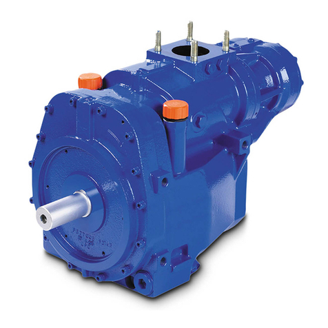
Mouvex B200 User manual

Quick Start Guide
SCREW COMPRESSORS –
B200
Thoroughly review the manual, all instructions, and hazard warnings BEFORE installing, using, and performing
any maintenance on the equipment.
Manuals are available for download using the QR code and at mouvex.com.
Attempting installation, operation, and disassembling/reassembling of the equipment without reading and
following
manual instructions could lead to SAFETY risks and irreparable DAMAGES to the equipment.
Lisez attentivement le manuel, toutes les instructions et les avertissements de danger AVANT l’installation, l’utilisation et
l’entretien du matériel .
Les notices sont disponibles par téléchargement , Utilisez le QR code et dans le site internet mouvex.com.
Tenter d’installer, d’utiliser et de démonter/remonter le matériel sans lire et suivre les recommandations de la notice peut conduire à des
risques en termes de SECURITE et des DOMMAGES IRRÉVERSIBLES sur le matériel.
Lesen Sie das Handbuch mit allen Anweisungen und Gefahrenhinweisen VOR der Installation, der Nutzung und der Durchführung
von Wartungsarbeiten an das gerät gründlich durch.
Handbücher stehen zum Download über den QR-Code und unter mouvex.com zur Verfügung.
Die Installation, der Betrieb, die Demontage bzw. Montage das gerät ohne vorheriges gründliches Lesen und das Befolgen der
Anweisungen des Handbuches kann zu SICHERHEITSRISIKEN und irreparablen SCHÄDEN an das gerät führen.
Revise a fondo el manual, todas las instrucciones y advertencias de peligro ANTES de instalar, de utilizar o de realizar cualquier
mantenimiento en el equipo.
Los manuales se pueden descargar usando el código QR y en mouvex.com.
Intentar instalar, hacer funcionar o desmontar / remontar el equipo sin leer y seguir las instrucciones de los manuales podría generar
riesgos de SEGURIDAD y DAÑOS irreparables para el equipo.
Revisionare attentamente il manuale, tutte le istruzioni e gli avvisi di pericolo PRIMA installazione, uso ed esecuzione di qualsiasi
intervento di manutenzione il materiale.
I manuali sono disponibili per il download utilizzando il codice QR e su mouvex.com.
Il tentativo di installazione, funzionamento e smontaggio / rimontaggio il materiale senza lettura e seguendo le istruzioni manuali
potrebbe portare a rischi di SICUREZZA e danni irreparabili il materiale.
IMPORTANT! |IMPORTANT! |WICHTIG! | ¡IMPORTANTE! | IMPORTANTE!
EN
FR
DE
ES
IT
EN
FR
DE
ES
IT
Date : | Date : | Marke : | Fecha : | Data : Serial number : | N° série : | Serial-Nummer : | Número de serie : | Numero di serie :
Type : | Type : | Typ : | Tipo : | Tipo : o12R PF o12R PS o12R HY
o10L PF o10L PS o10L HY
TRUCK | VEHICULE | FAHRZEUG | VEHICULO | VEICOLO
Brand : | Marque : | Marke : | Marca : | Marchio : Type : | Type : | Typ : | Tipo : | Tipo :
Gear Box : | Boîte de vitesse : | Schaltgetriebe : | Caja de cambios : | Cambio : PTO : | Prise de force : | Zapfwelle : | Toma de fuerza : | Presa di forza :
Filter : | Installateur : | Installierer : | Instalador : | Installatore : User : | Utilisateur : | Anwenders : | Usuario : | Utilizzatore :
CONTROL CHECK LIST Installation Of The Compressor B200 Flow control
This document does not take the place of the recommendations of the instructions with which we
recommend you very deeply to acquaint.
CHECK LIST DE CONTROLE Installation Compresseur B200 Flow control
Ce document ne se substitue pas aux recommandations de la Notice d’instructions
dont nous vous recommandons très vivement de prendre connaissance.
KONTROLL-CHECKLISTE Installation Kompressor B200 Flow control
Diese Unterlage ersetzt nicht die Empfehlungen der Bedienungsanleitung,
die wir Ihnen nachdrücklich empfehlen, aufmerksam durchzulesen.
LISTA DE CONTROL Instalación Compresor B200 Flow control
Este documento no sustituye las recomendaciones del Manual de Instrucciones,
las cuales le recomendamos encarecidamente que lea con atención.
CHECK LIST DI CONTROLLO Installazione Compressore B200 Flow control
Tale documento non sostituisce le raccomandazioni contenute nel manuale d’uso
al quale si prega vivamente di fare riferimento.

32
EN
A. Fixation of the compressor B200 version PF
o1Using of the kit delivered by MOUVEX Integrating the metallic
gasket, the 4 Nord Lock washers and the 4 nuts.
o2Nuts tightened to 37 Nm.
o3Dripstone turned down.
o4Screws tightened at 13 Nm.
Quick Start Guide |SCREW COMPRESSORS – B200
CONTROL CHECK LIST
Installation Of The Compressor B200 Flow control
B. Suction
1Air Filter
o•Rain cap in place.
o•Clogging indicator visible.
o•Cartridge in place and clean.
2Hose (supplied with the compressor) :
o•1. Hose adjusted to the installation. Clean inside.
o•2. & 3. Nipples in place on the hose.
o•4. Heat shrinkable sleeves in place.
o•5. & 6. Clamps in place and tightened.
B. Discharge
o1The graphite ange gasket MOUVEX (REF 228065) is in place.
o2Screws tightened at 44 Nm.
o3A 90° elbow is tted on the ange.
o4PF version: the discharge hose delivered is tted on that elbow. If arrow presence, turn the hose in the good direction.
o5Other versions (PS et HY): the piping tted on the elbow has a downward slope.
o6All the connections must be welded.
o7Silencer (option)
o8Rigid pipe Ø 1" ½
o9Check Relief valve MOUVEX
o10 There is a plug at the end of the pipe.
o11 The waterproofness of the whole piping has to be checked.
5 3 4 1 4 2 6

Conform Conform
D3 C10
32
D. Compressor B200
o1Maximum slope is 10°.
o2Oil BSC2 inside at the right level.
o3Breather tted at the upper point if the compressor is sloped.
o4The breather hose is not shortened, not folded and with an upward slope.
o5The breather hose is xed with collars.
o6The breather is not plugged and is xed.
o7There is a torque limiter set to 400 Nm on the PS version.
EN
E. Test of the Compressor B200
o1Make sure the compressor rotates in the right direction (see the Instructions).
o2Speed control (recommended : 1 only point matching with the maximum speed) :
oLeft Screw N mini N maxi
oRight Screw N mini N maxi
WARNING : Consult the Instructions 1401-X00 regarding the speed range.
o3Gear box split position : oLow oHigh
o4The split selected is locked.
o5The speed range used is locked.
o6Relief valve pressure : o2 bar o2,3 bar o2,5 bar
o7Control of the opening of the relief valve.
WARNING : Ban to insert a dumping valve on the pipe linking the compressor to the tank hose connector 10.
10°
10°

54
A. Fixation Compresseur B200Version PF
o1Usage du kit livré par MOUVEX incluant le joint métallique, les
4 rondelles Nord Lock et les 4 écrous.
o2Ecrous serrés à 37 Nm.
o3Larmier orienté vers le bas.
o4Vis serrées à 13 Nm.
Quick Start Guide |SCREW COMPRESSORS – B200
CHECK LIST DE CONTROLE
Installation Compresseur B200 Flow Control
B. Aspiration
1Filtre
o•Chapeau pare pluie en place.
o•Indicateur de colmatage visible.
o•Cartouche en place et propre.
2Flexible (fourni avec le compresseur) :
o•1. Flexible ajusté à l’installation. Propre à l’intérieur.
o•2. & 3. Manchons en place sur exible.
o•4. Gaines thermo rétractables en place.
o•5. & 6. Colliers en place et serrés.
B. Refoulement
o1Présence du joint de bride MOUVEX en graphite REF 228065.
o2Vis serrées à 44 Nm.
o3Usage d’un coude à 90° sur la bride.
o4Version PF : le exible livré est monté sur ce coude. Si présence èche, orienter le exible dans la bonne direction.
o5Autres versions (PS et HY) : la tuyauterie montée sur le coude présente une contre pente.
o6Tous les raccords doivent être soudés.
o7Silencieux (option).
o8Tuyauterie rigide Ø 1" ½
o9Combiné clapet / soupape MOUVEX
o10 Présence d’un bouchon sur la boîte symétrique.
o11 Contrôle de l’étanchéité de la ligne complète.
FR
5 3 4 1 4 2 6

Conforme Conforme
D3 C10
54
D. Compresseur B200
o1Inclinaison maximale de 10°.
o2Présence d’huile BSC2 et niveau correct.
o3Reniard monté en point haut si le compresseur est incliné.
o4Flexible non raccourci, non plié et en pente ascendante.
o5Flexible maintenu par des colliers.
o6Reniard xé et non obstrué.
o7Présence limiteur de couple taré à 400 Nm sur version PS.
E. Test du Compresseur B200
o1Respect du sens de rotation (schéma Notice d’instructions).
o2Contrôle des vitesses (recommandé : un seul point correspondant à la vitesse maxi) :
oVis gauche : N mini N maxi
oVis droite : N mini N maxi
Attention : Consulter la Notice d’instructions 1401-X00 concernant les plages de vitesse.
o3Position du relais de boîte de vitesse : oLente oRapide
o4Verrouillage de la vitesse lente / rapide (relais).
o5Verrouillage de la vitesse mini / maxi.
o6Pression de la soupape : o2 bar o2,3 bar o2,5 bar
o7Contrôle de déclenchement de la soupape.
Attention : Interdiction d’intégrer une vanne de mise à l’air sur la tuyauterie
reliant le compresseur à la boite symétrique 10.
FR
10°
10°

76
Quick Start Guide |SCREW COMPRESSORS – B200
KONTROLL-CHECKLISTE
Installation Kompressor B200 Flow Control
B. Ansaugseite
1Filter
o•Regenschutzkappe aufgesetzt.
o•Verstopfungsanzeige sichtbar.
o•Filtereinsatz angebracht und sauber.
2Schlauch (Lieferumfang des Kompressor) :
o•1. Ansaugschlauch mit angepasster Länge. Innen sauber.
o•2. & 3. Manschetten an beiden Enden des Schlauches vorhanden.
o•4. Schrumpfschläuche angebracht.
o•5. & 6. Sicherungschelle angebracht und angezogen.
A. Befestigung Kompressor B200 Ausführung PF
o1Verwendung des von MOUVEX gelieferten
Sets bestehend aus Metalldichtung,
4 Scheiben Nord Lock und die 4 Muttern.
o2Muttern, angezogen mit 37 Nm.
o3Kranzleiste mit Bohrung nach unten gerichtet.
o4Schrauben, angezogen mit 13 Nm.
B. Förderseite
o1MOUVEX Flanschdichtung aus Graphit REF 228065 gegenwärtig.
o2Schrauben, angezogen mit 44 Nm.
o3Verwendung eines 90° Kniestücks am Flansch.
o4Ausführung PF : Der Schlauch im Lieferumfang ist an dieses Kniestück montiert.Wenn Richtungspfeil vorhanden, Orientierung
des Schlauchs in die richtige Richtung.
o5Andere Ausführungen (PS und HY) : Die am Kniestück montierte Rohrleitung weist eine Gegenneigung auf.
o6Gewinde und Flanschverbindungen müssen in der Druckverrohrung dauerhaft dicht verschweißt werden.
o7Schalldämpfer (Option).
o8Starre Rohrleitung Ø 1" ½.
o9MOUVEX Rückschlag- und Sicherheitsventil.
o10 Vorhandensein eines Stopfens am symmetrischen Getriebe.
o11 Dichtigkeitskontrolle der kompletten Linie.
DE
5 3 4 1 4 2 6

Konform Konform
D3 C10
76
D. Kompressor B200
o1Maximale Neigung 10°.
o2AusschliesslicheVerwendung von BSC2 Öl und korrekter Füllstand Stand.
o3Entlüfter am obersten Punkt, wenn Kompressor geneigt.
o4Schlauch nicht verkürzt, nicht gequetscht und abfallende Neigung.
o5Entlüfter befestigt und nicht verstopft.
o6The breather is not plugged and is xed.
o7Vorhandensein eines Drehmomentbegrenzers, geeicht auf 400 Nm auf
Ausführung PS.
Achtung : Integrierung eines Luftventils auf der Rohrleitung ;
vom Kompressor bis zum symmetrischen Getriebe 10 ist verboten.
DE
E. Test des Kompressors B200
o1Einhalten der Drehrichtung (Schema Betriebsanleitung).
o2Kontrolle der Geschwindigkeiten (empfohlen : festeingestellte maximal Drehzahl) :
oSchraube links : N mini N maxi
oSchraube rechts : N mini N maxi
Achtung : Siehe Betriebsanleitung 1401-X00 betreffend Geschwindigkeitsbereiche.
o3Relaisposition des Schaltgetriebes : oLangsam oSchnell
o4Verriegeln der langsamen / schnellen Geschwindigkeit (Relais).
o5Verriegeln der min. / max. Geschwindigkeit.
o6Ventildruck : o2 bar o2,3 bar o2,5 bar
o7Kontrolle der Auslösung desVentils.
10°
10°

98
Quick Start Guide |SCREW COMPRESSORS – B200
LISTA DE CONTROL
Instalación Compresor B200 Flow Control
B. Aspiracion
1Filtro
o•Protector de lluvia instalado.
o•Indicador de obstrucción visible.
o•Cartucho montado y limpio.
2Manguera (suministrada con el compresor) :
o•1. Manguera correctamente ajustada en su lugar de
instalación. Interior limpio.
o•2. & 3. Manguitos montados en manguera.
o•4. Manguitos de termocontracción en su lugar.
o•5. & 6. Abrazaderas montadas y apretadas.
A. Fijación Compresor B200Versión PF
o1Uso del conjunto entregado por MOUVEX que incluye la junta
metálica, las 4 arandelas Nord Lock y los 4 tornillos.
o2Tuercas apretadas a 37 Nm.
o3Colector orientado hacia abajo.
o4Tornillos apretados a 13 Nm.
B. Descarga
o1La junta de brida de grato MOUVEX, REF 228065 está en su sitio.
o2Tornillos apretados a 44 Nm.
o3Uso de un codo de 90° en la brida.
o4Versión PF: la manguera suministrada se monta en este codo. Si presencia echa, orientar manguera en la buena dirección.
o5Otras versiones (PS y HY): la tubería montada en el codo hace una pendiente descendente.
o6Todas las conexiones deben estar soldadas.
o7Silenciador (opcional).
o8Tubería rígida Ø 1" ½
o9Clapeta / válvula MOUVEX
o10 El tapón en la caja simétrica ha sido colocado.
o11 Control de estanqueidad de la línea completa.
ES
5 3 4 1 4 2 6

Conforme Conforme
D3 C10
98
D. Compresor B200
o1Inclinación máxima de 10°.
o2Se ha puesto el aceite BSC2 y su nivel es correcto.
o3Respiradero montado en un punto elevado si el compresor
está inclinado.
o4Manguera no acortada ni doblada y en pendiente ascendente.
o5Manguera sujeta mediante abrazaderas.
o6El respiradero ha sido jado y no está obstruido.
o7Presencia de limitador de par ajustado a 400 Nm para la versión PS.
Atención : Prohibido instalar una válvula de ventilación
entre la salida del compresor y el acople de descarga 10.
ES
E. Prueba del Compresor B200
o1Asegurarse que el compresor gira en sentido correcto (esquema Manual de instrucciones).
o2Control de velocidad (recomendado : un solo punto que corresponda a la velocidad máxima) :
oTornillo izquierda : N mini N máxi
oTornillo derecho : N mini N máxi
Atención : Consulte el Manual de instrucciones 1401-X00 con referencia a los rangos de velocidad.
o3Posición del relé de la caja de cambios : oLenta oRápida
o4Bloqueo de la velocidad lenta/rápida (relé).
o5Bloqueo de la velocidad mínima / máxima.
o6Presión de la válvula : o2 bar o2,3 bar o2,5 bar
o7Control de apertura de la válvula.
10°
10°

1110
Quick Start Guide |SCREW COMPRESSORS – B200
CHECK LIST DI CONTROLLO
Installazione Compressore B200 Flow Control
B. Mandata
o1Presenza del giunto a angia MOUVEX in grate REF 228065.
o2Viti serrati a 44 Nm.
o3Uso di un gomito a 90° sulla angia.
o4Versione PF : Il tubo essibile fornito è montato a gomito. Se presenza freccia, orientare il essibile nella giusta direzione.
o5Altre versioni (PS e HY) : la tubazione montata a gomito presenta una contropendenza.
o6Tutti i raccordi devono essere saldati.
o7Silenziatore (opzione).
o8Tubazione rigida Ø 1" ½
o9Valvola di non ritorno / valvola di sovrapressione MOUVEX
o10 Presenza di un tappo sulla boccola simmetrica.
o11 Controllo della tenuta di tutta la linea.
A. Fissaggio Compressore B200 Versione PF
o1Uso del kit fornito da MOUVEX, compreso di giunto metallico, e
4 rondelle Nord Lock e i 4 dadi.
o2Dadi serrati a 37 Nm.
o3Gocciolatoio orientato verso il basso.
o4Viti serrate a 13 Nm.
IT
B. Aspirazione
1Filtro
o•Cappello parapioggia predisposto.
o•Indicatore di intasamento visibile.
o•Cartuccia predisposta pulita.
2Flessibile (fornito con al compressore) :
o•1. Flessibile regolato all’installazione. Internamente pulito.
o•2. & 3. Riduzioni in gomma per essibile.
o•4. Guaina termo restringente.
o•5. & 6. Fascette predisposte e serrate.
5 3 4 1 4 2 6

Conforme Conforme
D3 C10
1110
D. Compressore B200
o1Inclinazione massima di 10°.
o2Presenza d’olio BSC2 e livello corretto.
o3Valvola di aspirazione montata in alto se il compressore è inclinato.
o4Tubo essibile non accorciato, non piegato e in pendenza a scendente.
o5Flessibile sorretto da fascette.
o6Valvola di aspirazione ssata e non ostruita.
o7Presenza di limitatore di coppia regolato a 400 Nm su versione PS.
Attenzione : E’Divieto integrare una valvola di sfiato aria sulla tubazione
che collega il compressore alla boccola simmetrica 10.
IT
E. Test del Compressore B200
o1Rispetto del senso di rotazione (schema Istruzioni).
o2Controllo della velocità (raccomandato : un unico punto corrispondenza alla velocità massima) :
oVite sinistra : N mini N massi
oVite destra : N mini N massi
Attenzione : Consultare il Istruzioni 1401-X00 concernente i campi di velocità.
o3Posizione del relè del cambio di velocità : oLenta oRapida
o4Blocco velocità lenta / rapida (relè).
o5Blocco velocità minima / massima.
o6Pressione della valvola : o2 bar o2,3 bar o2,5 bar
o7Controllo di sblocco della valvola.
10°
10°

ZI la Plaine des Isles •2 rue des Caillottes
F-89000 AUXERRE - FRANCE
Tel: + 33.3.86.49.86.30 •Fax: + 33.3.86.46.42.10
mouvex.com
MVX-90004-F-01-A4
Quick Start Guide |SCREW COMPRESSORS – B200
© 2018 MOUVEX
EN FR DE ES
English Français Deutsch Español Italiano
IT
Table of contents
Languages:
Other Mouvex Air Compressor manuals
Popular Air Compressor manuals by other brands

General Air Products
General Air Products Dry Air Pac DAP500 Installation, operation and maintenance manual
Clas Ohlson
Clas Ohlson HD-055 instruction manual
FScurtis
FScurtis SEG-5 Operator's manual
Scheppach
Scheppach AIR FORCE 2 Translation of original instruction manual
Durr Technik
Durr Technik KK15 Installation and operating instructions
Craftsman
Craftsman 919.72427 owner's manual
