Movacolor MC-BALANCE User manual

Load cell
External communication /
Network
Mains
p
ower switch: ON / OFF
Mains
p
ower cable
Start in
p
ut cable
Motor cable Valve output
for ho
pp
er loade
r
Output for:
-Alarm
-Warning
-Running
Input LED is lighted:
input signal is ON
Alarm LED is lighted:
alarm / warning
Enter / scroll / exit MENU
Start LED blinking:
motor is stand by / waiting for start signal
Start LED lighted:
motor is running
Arrow up / down:
Scroll through parameters
Arrow left / right:
Scroll through menus
A
lphanumerical
buttons:
Set values /
descriptions
Enter:
Confirm settings
Start:
Start unit
Stop:
Stop unit
MC-BALANCE Quick Reference 4.0 UK.00
Part 1: Operation Reference
For more detailed information please consult the User Manual
GENERAL
1. Terminal software version V0.08.
2. Operation software version V4.0, production date April 2008.
3. Connect motor and load cell before switch on the controller.
4. All changes have to be confirmed with
START UP
Directly after switching ON the main power of the MC-Balance, the software versions will be displayed.
LOGIN <menu>
The MC-Balance has 3 user levels defined:
User Level Access level
1. Operator production settings / hopper loader settings
2. Tooling same as operator & additional material calibrations / job functionality / weight check / consumption /
alarm history / event log.
3. Supervisor same as tooling & additional system configuration / alarm configuration / file management /
load cell calibration.
Key lock: (un)locked. No changes can be made in the settings. The keyboard can be (un)locked by the supervisor.
For changing to an other user level, enter the LOGIN menu and fill in the password (4 numerals) and confirm.
Login for Operator is 0000. The passwords for the other two user levels are defined by the supervisor.
When entering a wrong password, user level will be set automatically to operator level.
In OPERATOR LEVEL the following menus are available:
PRODUCTION / HOPPER LOADER / LOGIN.
PRODUCTION <menu>
The following parameters can be seen in the production screen, depending on operation or settings, (made in supervisor mode):
Injection molding Extrusion
Prod Job: Name of the production Job Prod Job: Name of the production Job
Set speed: Rotating speed of the motor [RPM mode] Set speed: Rotating speed of the motor [RPM mode]
Dos. Time: Dosing time (sec.) [Timer mode] Max. tacho: Maximum tacho voltage (V)
Material: Name of material calibration Material: Name of material calibration
Color%: Color amount (%) Color%: Color amount (%)
Shot wth: Shot weight (gr.) Ext. cap: Maximum extruder capacity (kg/hr)
Test: Select Test, select YES and confirm . The unit will run with the set parameters.
Test time in extrusion mode is 30 seconds.
Production (Motor On/Off)
Press to start production, the question appears Fill cylinder? YES/NO. YES means that the dosing cylinder will be filled. press to
stop production. When the unit is started, the actualproduction data will be shown.
The start LED blinks when the unit is waiting for an input signal. The unit is dosing if the Start LED lights continuously.
Regulation mode: AUTO / MANUAL. In theMANUAL mode can be run with fixed RPM. The regulation is frozen.
HOPPER LOADER <menu>
The following parameters can be seen in the production screen, depending on operation or settings (made in supervisor mode):
In this menu all the hopper loader parameters can be set.
ME hopper loader (Movacolor hopper loader operated by compressed air)
ME system : Enable / disable ME hopper loader. (On / Off)
ME fill time: Fill time (sec.) after the weight is above the hopper fill weight (CONFIG.) again (0,0-99,9 sec.)
ME alarm time: Alarm time (sec.) Time between hopper empty weight (CONFIG) and (1,0-99,9 sec.)
start of alarm, alarm time > fill time.
ME alarm mode: ME hopper loader is ON / OFF during fill alarm.
Manual fill: Yes = start filling immediately; No = Stop filling immediately.
MV hopper loader (Movacolor hopper loader operated by vacuum)
MV system: Enable / disable MV hopper loader. (On / Off)
MV fill time: Fill time (sec.) (0,0-99,9 sec.)
MV empty time: Empty time (sec.) of MV loader before the next cycle. (0,0-99,9 sec.)
MV fill cycles: Number of additional fill cycles after the weight is above the hopper fill weight again (0-99)
MV alarm cycles: Number of total fill cycles until fill alarm appears if hopper weight stays to low. (0-99)
MV alarm mode: MV hopper loader is ON / OFF during fill alarm.
Manual fill: Yes = start filling immediately; No = Stop filling immediately.
EX hopper loader (Support frame for external hopper loader)
EX system: Enable / disable the Support frame system.
Alarm time: Alarm time (sec.) Time between hopper empty weight (CONFIG) and (1,0-99,9 sec.)
start of alarm.
Alarm mode: EX hopper loader is ON / OFF during fill alarm.
ON = The system stays activated during a filling alarm.
OFF = The system will be deactivated during a filling alarm.
Manual fill: Yes = starting filling immediately; No = stop filling immediately
MC-BALANCE Quick reference Part 1 Operation Reference

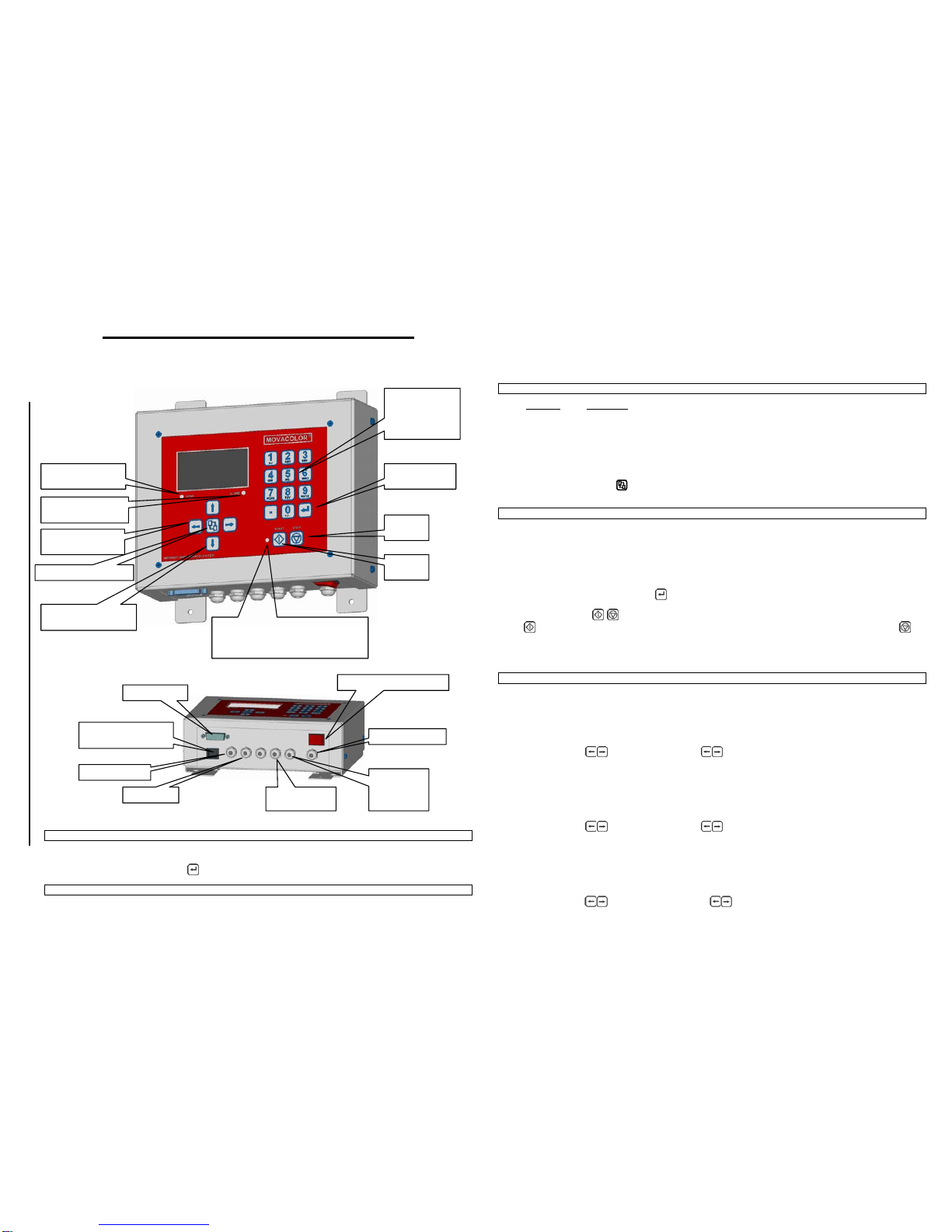
Part 2: Installation Reference MC-Balance
For more detailed information please consult the User Manual
GENERAL INFORMATION
•Use the equipment only for what it is designed for. The metering of dry additives!
•Before switching on the unit for the first time, ensure that the main power voltage being applied is between 80 and 260Vac.
•Always switch off the Movacolor control cabinet and disconnect from electrical power before performing maintenance.
•The symbol certifies that the machine conforms to the European Union regulations on minimum safety standards.
•Make sure all parts are securely fixed to your extruder or injection molding machine.
LOGIN <menu> supervisor level
The MC-Balance has 3 operation / user levels defined:
User level Default code Access
•Operator 0000 production settings / hopper loader settings / weight check / consumption /
alarm history.
•Tooling 1111 same as operator & additional material calibrations / job functionality.
•Supervisor 2222 same as tooling & additional system configuration / alarm configuration /
file management / load cell calibration.
Password forgotten: Consult user manual.
Entered the wrong password, user level will be set automatically to operator level.
Key lock: The key board can be (un)locked here. User level will be set automatically to operator level.
CONFIGURATION <menu> supervisor level
For initial setup the MC-Balance controller needs to be configured in the SYSTEM menu once. Depending on the settings, some
parameters will be (in)visible in case they are not relevant.
Explanation of the parameters:
•Language: Standard language isEnglish. On request also different languages are available.
•Motor type: LT is Low Torque motor and HT is High Torque motor
•Cylinder type: Type of dosing cylinder / feed screw (see manual for all types)
•Material type: Type of material, normal granules (NORMAL) and micro granules (MICRO)
•CAL dev: Calibration deviation, Maximum allowed deviation during material calibration.
•Control mode: Gravimetrical mode (GRAVI) or Rotating mode (RPM)
•Prod. Mode: select, extruder (EXT) or injection molding (INJ)
•Input mode: Type of input signal. Relay, Timer or Tacho (only with extruder)
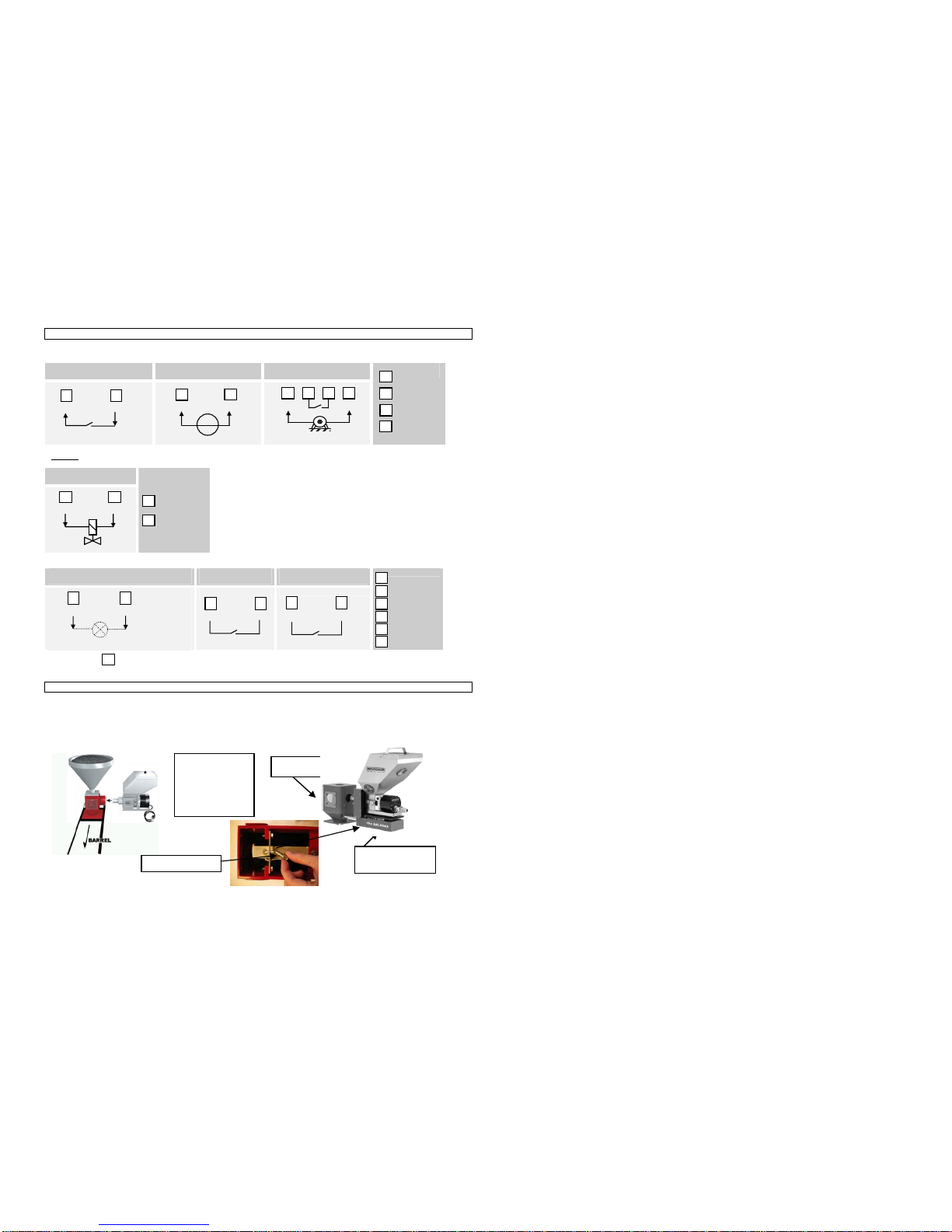
•Fill. System: Filling system, ME / MV / EX
•Filling start: When the material weight in the hopper is below this value (800gr.), the filling starts
•EX-H level: The filling knife gate valve will close if the weight in the hopper is 2500 grams (default) or more.
•EX-HH level: HH level is High level warning. If the weight in the hopper reaches 3000 grams (default) or more.
•Hopper Empty: When the material weight in the hopper is below this value (700gr.) this alarm appears.
•Deviationalarm: Deviation % setting with reference to the maximum deviation alarm.
•Jobs enabled: Enable / disable production job functionality
•Auto start: Enable / disable auto startup after Voltage dip or main power has been switched OFF.
•Master reset: Reset alarm history (ALARMS) / material calibrations (MATER.) /
production jobs (JOBS) or all of these resets together (ALL)
•IP: IP-address for use in a network environment
•Name: Give a name or figures for individual identification (for use in network)
•Start user: User level to start up with, when switching on the controller’s main power
•Tooling password: Password for Tooling user level, 4 numerals, default 1111
•Supervisor password: Password for Supervisor user level 4 numerals, default 2222
•Conversion: Selevtion of units: Metric [gr/s] / Imp [lbs/hr] / kg/h [instead of gr/s]
•Full scale: Selected loadcell will be shown
•Modbus unit: Unique identity when used in modbus network
•Date: Actual date (dd / mm / yy)
•Time: Actual time (hh / mm / ss)
LOAD CELL <menu> Supervisor level
In this menu it is possible to perform a load cell calibration. (500gr. Calibration weight required)
Always perform a load cell calibration after the machine is installed, with an empty hopper, the motor and hopper lid mounted.
Make sure that the controller is ON for at least 15 minutes and the system must be stable during calibration.
•Go to the LOAD CELL CALIBRATION menu.
•Follow the screens.
WEIGHT CHECK <menu> Tooling / Supervisor level
The following parameters will be shown in this menu:
•Weight: Actual weight on the weighing scale.
•Object: Object weight.
•Zero: Zero YES / NO the object weight.
If the Object weight is not corresponding with the real weight, perform a load cell calibration.
CALIBRATION <menu> Tooling / Supervisor level
The MC-Balance can be started in mainly two ways:
1)Start the unit without pre-calibration of material.
After pressing the START button the unit starts dosing on a speed that is based on default curves which are pre-programmed in the
controller.
2) Start the unit with pre-calibration of material.
After pressing the START button the unit starts dosing on a speed that is based on calibrations made by the user which are stored in the
controller
A material calibration can be made as follows:
AUTOMATIC, Calibration (complete curve) based on the internal reference curves
•Configure the controller in control mode GRAVI.
•Go to the CALIBRATION menu.
•Enter your production parameters, follow the screens and start calibrating.
•It is possible to stop during the calibration (for example to refill the hopper). To continue select YES
and confirm. To stop, select NO and confirm.
•After saving you will automatically go to the PRODUCTION menu and stored calibration is automatically selected.
PRODUCTION <menu> Tooling / Supervisor level
The following EXTRA parameters are displayed in the production screen when logged in as Tooling / supervisor
(depending on configuration):
Extrusion
Ext. cap: Maximum extruder capacity (kg/hr). This value will be coupled to the max. tacho voltage.
Max. tacho: This value (Volts) will be coupled to Ext. cap. (kg/h)
Set tacho: Automatic tacho voltage take over from tacho generator by selecting YES/NO and confirm or
enter tacho voltage manuallyat Max. tacho.
After changing back to operator mode these settings (excl. set tacho) are displayed but can not be changed.
When job function is enabled (in configuration menu) the following parameters will be displayed:
Prod Job: Name of the production Job (For a Job list, press <Enter> for 2 seconds)
Save Job: Save Job into the Job list
Following data will be stored with a JOB, depending on the configuration:
•Configuration settings: Control mode / Prod. mode / Input mode
•Production settings: Job description / Shotwth. / color% / dos.time / Ext. cap. / Max. tacho / RPM
•Material calibration
For a Material calibration list, go to Material and press for 2 seconds. The material descriptions can be made in the tooling or
supervisor level.
Regulation mode: Auto/Manual (this function is only visible when the unit is started)
This function allows to switch from automatic control (Gravimetrical) to manual control (RPM).
Save data (this function is only visible when the unit is started)
With this function the actual data (RPM) can be stored. A material description needs to be entered to store the actual data.
After startup with the stored material description, the unit will run with the stored RPM.

ALARMS <menu> Supervisor level
Display of the alarm history.
Press to scroll to the stored alarms.
The alarm history can be reset by the supervisor.
When a problem occurs using the MC-Balance , the display will indicate an error code and description. Also the alarm LED lights up.
Together with the displayed error an output contact can be switched.
To reset an alarm / warning during production press Stop or / and menu .
Free programmable errors can be configured to an Alarm or Warning.
Warning: Warning output is ON, but the dosing unit continues running (24VDC contact)
Alarm: Alarm output is ON and the dosing unit stops running (Potential free contact)
For setting the free programmable outputs into alarm or warning, enter the ALARMS menu. First the alarm history will be shown. The
alarms and warnings will be stored inhere. The alarm history can be reset by master reset ALARMS in CONFIGURATIONS menu.
When you press the menu button again you will enter the alarm configuration menu.
Here you can set the alarm- or warning output with and confirm.
Error
code Alarms / Warnings , Free programmable Description
00 Low hopper level Material is below the hopper empty weight, set in Configuration menu
01 Maximum deviation exceeded The deviation of the material output is higher than the set value in CONFIGURATIONS menu
Warnings, Non adjustable
02 Filling system unable to load material Fill system is not working correct
03 Maximum RPM exceeded, change dosing tool for
higher capacity Calculated motor speed is too high
05 Calibration, no weight change No weight change while calibrating
07 Minimum motor speed < 0,1 RPM Calculated motor speed is too low
06 EX-HH level Hopper weight has reached the EX-HH level
Alarms, Non adjustable
08 Motor connection failure: Motor not connected / Motor or connection damaged
09 Parameters damaged Check configuration parameters
10 Parameters set to factory defaults Check parameters
11 Load cell calibration set to factory defaults Recalibrate the load cell
12 Job and curve database initialized Jobs and Materials are reset
13 Load cell connection failure Load cell connection is not correct
All warnings are self eliminating except Errorcode 05. It is possible to push the warnings away, but when the error remains, it will be back
after 60 seconds.
CONSUMPTION <menu> Tooling/ Supervisor level
The following parameters will be shown in this menu:
•Batch: Consumption of a batch
•Batch Reset:Reset the consumption
•Total: Consumption (total quantityof dosed material in kg.) only when hopper loader is selected.
•Total Reset: Reset both the Batch and Total consumption.
FILES <menu> Supervisor level
In this menu you can search for files and delete or rename them.
When you enter the file manager menu, you can select two file types: Material (material calibrations) or Jobs (Production jobs).
After confirming, you will enter the file list. You can search for files and delete or rename them.
Search: character and = The files that start with that specific character will be shown.
Search: and = Display all files
Search: = Scroll through the files.
= DELETE or RENAME a file. File will be deleted or renamed after confirming with <Enter>.
EVENT LOG Tooling / Supervisor level
The history of events or setting changes will be logged in this menu.
Optional:
Slide mechanism for material calibrations on the machine.
MC-Balance F.A.Q and Trouble shooting
GENERAL
The following variables may influence the accuracy and repeatability of the system:
1. Material properties. Easy flowing, non-sticky and non-static material that comes in the form of small regular shaped granules or
powder can be dosed very accurate and regular.
2. Periodical cleaning of the dosing cylinder and seals is necessary for proper operation.
3. Extreme vibrations and shocks can have negative influence on system performance.
4. Vacuum or overpressure in the neckpiece caused by driers or hopper loaders.
Besides the variables mentioned so far, with injection molding the shot to shot accuracy depends on the shot time in combination with
granule size and weight. If relatively big and heavy granules have to be dosed in a very short time, it will influence the shot accuracy and
repeatability, because if only a few granules are dosed during the shot, one granule more or less makes a big difference on the total shot
weight.
System is NOT starting up when switched ON by main power switch
1. Main fuse inside the controller can be blown
Color variations
1. Unstable relay or tacho signal.
2. Bridging or rat holing of the material inside the hopper can happen if the material is not free flowing.
3. Bridging or rat holing of the material inside the hopper can happen if the material is extremely static.
4. Extremely static material can contaminate the dosing cylinder.
5. In case of water cooled neckpiece, check if there is material build up around the dosing cylinder and the water cooled pipe. Check
also the water supply to the neckpiece.
Weighing is not correct
1. Check if transport protection is removed.
2. Weighing platform is touched by something that influences the weighing.
3. Hopper loader tubes are not fixed in the right way.
4. Safety bolts are not free / touching the frame.
Dosing position In calibration position
Weighing platform

ELECTRICAL INSTALLATION
Input signal to the MC-Balance can be made in the following ways, in accordance with the configuration.
Potential free contact
Potential contact
[Min 18VDC to Max.30VDC] Tacho
[Min 0VDC to Max. 30VDC]
Optional:
Hopper loader system
Valve output (24VDC)
Status outputs (Warning, Alarm and Running)
Warning Output
Potential contact(24VDC) Alarm Output
Potential free contact Running Output
Potential free contact
The numbers can be found on the printed circuit board
MECHANICAL INSTALLATION
1. All mechanical parts are pre-assembled, making installation quick and simple.
2. Remove transport protection (under side of the load frame) before installation!
3. Install the neckpiece directly on top of the entrance of the productionmachine.
a. Make sure that the complete unit is mounted horizontally leveled (water level) and fixed securely.
b. Assure proper grounding to control cabinet, neckpiece and dosing unit
4. Connect the unit to the neckpiece by turning curled knob clockwise.
5. Mount the controller vibration free and conform specified temperatures.
Mount the unit in a
90-degree angle to
the machine barrel.
As shown in the
picture.
26 27 28 29
22 23
+24VDC
Outp. 1
22 = White
23
26
27
28
29
= Brown
= Pink
= Grey
= Yellow
= Green
xx
25
24 +24VDC
Outp.2 24 = White
25 = Brown
Horizontally leveled
(Water level)
Neckpiece
Trans
p
ort
p
rotection
12 = Yellow
14 = White
15 = Brown
13 = Green
- +
14
12
+
1312 14 15
14 15
+ 24Vdc
INP1
GND
INP1
GND
Other manuals for MC-BALANCE
1
Other Movacolor Controllers manuals