Philadelphia Scientific iBOS Pro 6 Series User manual

DOC0006
Operations Manual
iBOS®Pro 6 Series
August 2018
Version 1.4

Philadelphia Scientific® iBOS®Pro 6 Series Operations Manual
Page 2 of 17
Table of Contents
iBOS®Pro 6 Series
1. Introduction..............................................................................................................................................3
1.1 System Overview...............................................................................................................................3
1.2 Organization of this Manual................................................................................................................3
1.3 Contact Information............................................................................................................................3
2. iBOS®Pro 6 Series Overview ..................................................................................................................4
2.1 System Components..........................................................................................................................4
2.2 System Details...................................................................................................................................5
3. Operating Instructions..............................................................................................................................6
3.1 Selecting the Next Available Battery ..................................................................................................6
3.2 System Feedback..............................................................................................................................6
3.3 Touchscreen Display..........................................................................................................................7
3.4 Status ................................................................................................................................................8
3.5 History................................................................................................................................................9
3.6 To Do...............................................................................................................................................10
3.7 Maintenance Mode ..........................................................................................................................10
3.8 Settings............................................................................................................................................11
4. Troubleshooting.....................................................................................................................................12
4.1 The Display Shows Dashes .............................................................................................................12
4.2 Troubleshooting from the Status Screen..........................................................................................12
4.2.1 Connected Not Charging...........................................................................................................13
4.2.2 No Battery Connected...............................................................................................................13
4.2.3 Quarantine................................................................................................................................13
4.2.4 Unknown...................................................................................................................................14
4.3 Sentinel™ Lights..............................................................................................................................14
4.3.1 Green LED –Communication status .........................................................................................14
4.3.2 Amber LED –Charging status...................................................................................................14
4.3.3 Blue LED –Termination status..................................................................................................14
4.3.4 Red LED –Bad communication cable.......................................................................................14
Appendix A –iBOS®System Daily Checks or Per Shift .............................................................................15
iBOS®System Checklist ........................................................................................................................16

Philadelphia Scientific® iBOS®Pro 6 Series Operations Manual
Page 3 of 17
1. Introduction
1.1 System Overview
This manual will give you all the information you need to operate the iBOS®battery management system.
This system helps create a smooth-running battery room and provides valuable management information
on the batteries and chargers.
1.2 Organization of this Manual
This manual has been divided into sections for each of the stages of an installation project:
•Section 2 –iBOS®Pro 6 Series Overview
•Section 3 –Operating Instructions
•Section 4 –Troubleshooting
1.3 Contact Information
Philadelphia Scientific LLC
207 Progress Drive
Montgomeryville, PA 18936
USA
Phone: 215-616-0390
Fax: 215-616-0500
Email: Info@phlsci.com
Philadelphia Scientific UK Ltd.
Atlas Mill
Bolton BL14LB
United Kingdom
Phone: +44 (0) 1204-467777
Fax: +44 (0) 1204-493300
Email: Info@ps-europe.net
Philadelphia Scientific-
Asia/Pacific
2/17 Norman Street
NSW, 2225
Australia
Phone: +61 2 8004-2447
Fax: +61 2 9012-0383
Email: Info@phlsci.com.au

Philadelphia Scientific® iBOS®Pro 6 Series Operations Manual
Page 4 of 17
2. iBOS® Pro 6 Series Overview
2.1 System Components
Control Box
Touch Screen Interface
Mounting Feet
Locking Tab
Built in Speaker
Sentinels™
(One per charger)
Scrolling Display –
(Optional) (One per pool)
Wireless Display
(Optional)
External Shouter (Optional)
Cellular Modem
(Optional)

Philadelphia Scientific® iBOS®Pro 6 Series Operations Manual
Page 5 of 17
2.2 System Details
Every charger has a small monitoring device attached to it called a Sentinel™that works on all voltages
(12-80v). The Sentinel’s™ basic function is to detect when the charger finishes charging and to tell the
Control Box that a fully charged battery is now available for use.
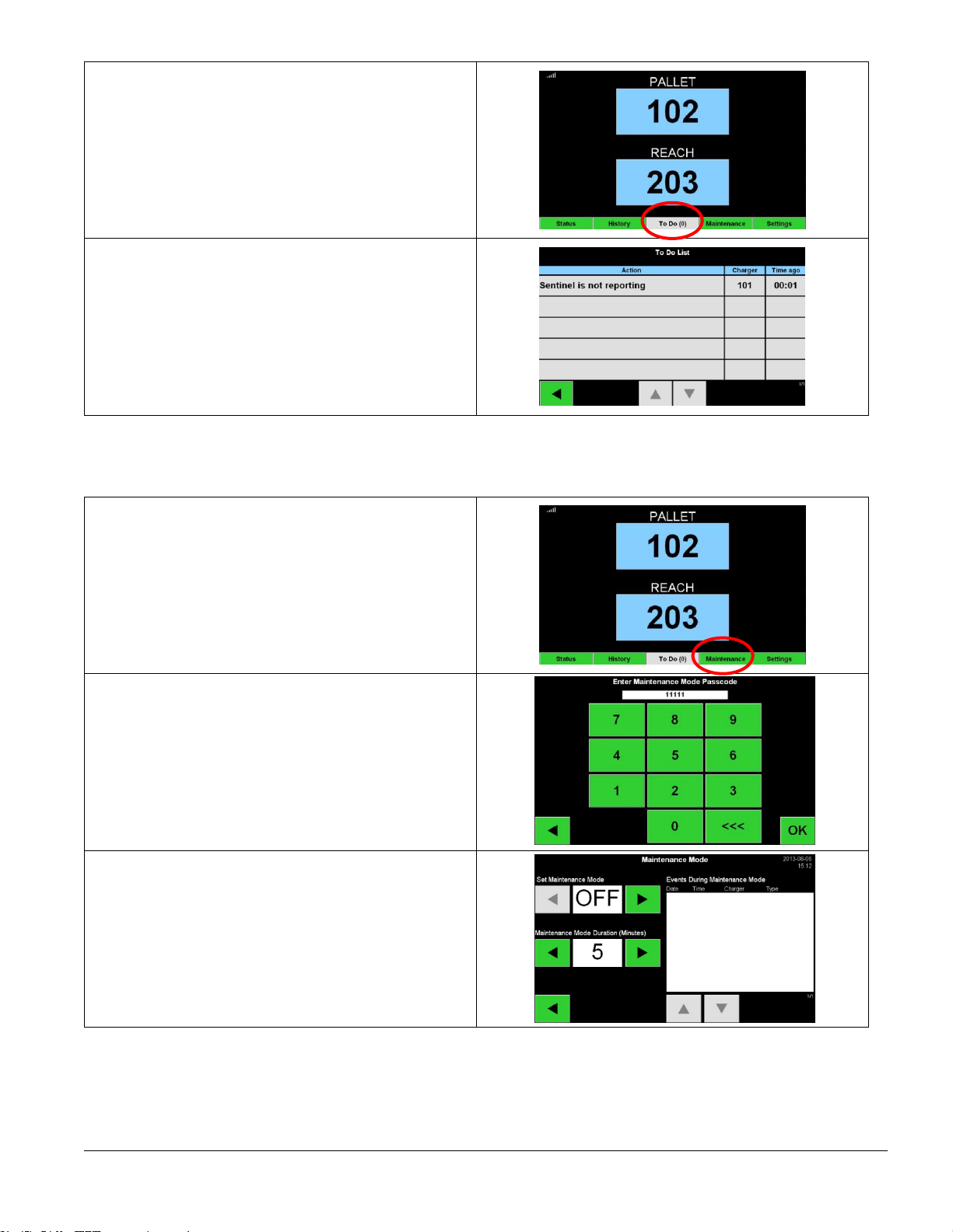
The Sentinel™also detects when a battery is connected without the charger starting. After 24 hours in this
state, the Sentinel™will terminate with a “Charger No Start” status and place the battery in Quarantine
status. After 72 hours the system will return the battery to the rotation, even though the battery was not
charged, to avoid stranding the battery indefinitely. A charger no-start record will appear on the iBOSworld
Web Service website indicating charger #, date, and time. These can also be seen by viewing the Status
screen on the control box.
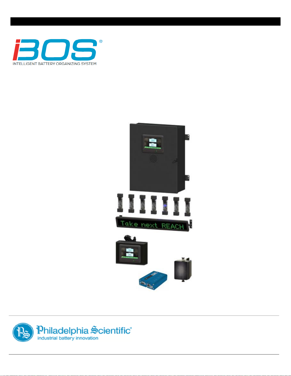
All Sentinels™are wired via a daisy chained bus into the Control Box which keeps track of all the charged
batteries. The chargers are grouped into pools, one pool for each type/size of battery in the facility. One or
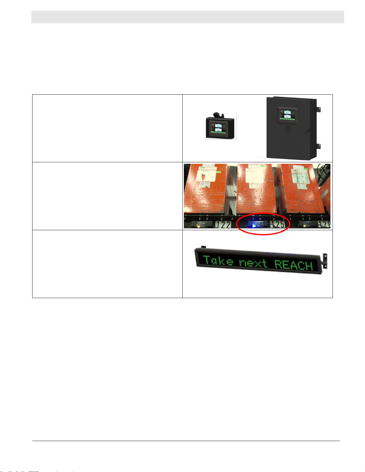
more scrolling LED displays, mounted on the wall, a wireless touchscreen display mounted on the battery
changer, or the touchscreen on the control box tell the operator which battery to pick next. The battery that
is fully charged and that has been cooled down the longest will appear on the display, assuming there are
no “Charger No-Start” batteries. There is also a built-in shouter which announces a message in one of
several languages telling the operator when they have picked an incorrect battery while a good pick sounds
a pleasant chime. This enables the system to ensure proper battery rotation.
The procedure for the operators is:
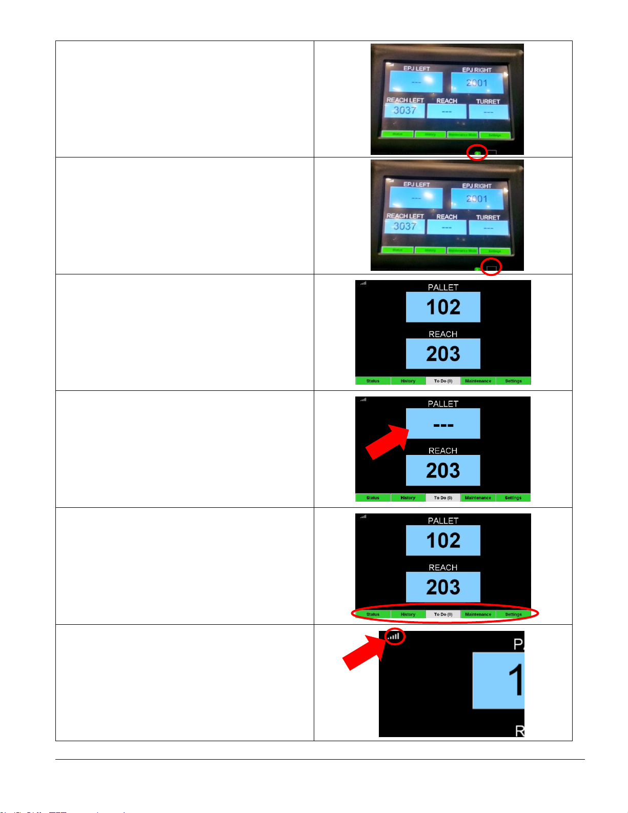
•When a truck comes in for a new battery, the operator looks at the touch screen display, scrolling
display, wireless display for that pool, or a blue light on a Sentinel™.
•It will tell him/her which battery to take. For example, they may see a message like: “Take next
REACH TRUCK battery from charger 102.”
•The operator goes to the slot marked “102” to get the battery for that type of truck.
The Control Box is also capable of sending data to a website where it can be processed, and reports are
generated. These reports contain information necessary for keeping the battery selection process running
smoothly and can be used to predict when a drift in process is due to too many/too few batteries,
malfunctioning chargers, and operators following instructions improperly. The connection to the internet is
either a standard direct network Ethernet or via cellular modem. The Ethernet method saves money over
the cellular service but requires IT department approval and installation. The cellular modem requires a
signal to a cell tower but can be a quick and reliable alternative.
Once data is being sent to the website, users who have the proper login permission can log into the
website and see information about the performance of the battery room. This information can help
determine if the site is running short of batteries or has too many, if all the chargers are working properly,
and if the operators are correctly following the instructions.

Philadelphia Scientific® iBOS®Pro 6 Series Operations Manual
Page 6 of 17
3. Operating Instructions
3.1 Selecting the Next Available Battery
Keep all batteries plugged in until they are selected unless they are selected for maintenance. The system
detects when a battery is connected to the charger, when the charger starts, when the charger finishes,
and how long the battery is connected to the charger before it is picked.
How to select next available battery:
Touchscreen Display
•The touchscreen display may be located
on the control box or also on the wireless
display.
•Select the battery listed for the specific
pool.
Blue LED
•Search for the charger with a Sentinel™
that has a blue LED illuminated. This is
the most ready battery.
•For example, in the photo to the right, the
operator should pick battery 125 as the
next battery.
Scrolling Display
•The scrolling display updates every 15
seconds.
•Take the battery from the charger
indicated by the display.
3.2 System Feedback
•The shouter on the control box and the external speaker sound with a pleasant chime when the
battery indicated by the system is selected.
•The shouter on the control box and the external speaker sound with an alarm and message when a
battery other than the one indicated by the system is selected. When this occurs, the system
considers it a “mispick”.
•All mispicks are logged by the system and can be viewed through the History tab on the Home
Screen of the touchscreen display or through the website, iBOSworld.

Philadelphia Scientific® iBOS®Pro 6 Series Operations Manual
Page 7 of 17
3.3 Touchscreen Display
Green LED
•Shows that the unit is powered.
The power button is next to the green LED. This
is the power button for the display only and not
the control box.
Home Screen
•Shows a list of pools and the next battery
to pick from each pool
Dashes are shown for a particular pool on the
display when no batteries are available. Dashes
for all pools can indicate that the system is in
Maintenance Mode.
When a button is green, it is an indication that
the button can be pressed.
The connectivity indicator is located in the upper
left of the Home screen. When it is at full
strength as shown, it shows that the touchscreen
is communicating normally with the control box.

Philadelphia Scientific® iBOS®Pro 6 Series Operations Manual
Page 8 of 17
3.4 Status
The Status button is located in the lower left of
the Home Screen.
Status Button
•Takes the user to a screen that shows the
current status of all of the chargers and
the queue.
The bottom of the Status screen lists the
following:
•Time since the last data was uploaded to
iBOSworld.
•The control box serial number.
•The current time/date.
Pressing on one of the Pool Names in green
causes the queue screen to appear.
The queue screen displays which chargers are in
each group.

Philadelphia Scientific® iBOS®Pro 6 Series Operations Manual
Page 9 of 17
3.5 History
The History button is located in the lower center
left of the Home Screen.
History Button
•Takes the user to a screen that shows the
record of picks, mispicks, zero available
picks, and minimum batteries available
for the last 7 days.
•Selections –The number of battery picks
for that pool.
•Mispicks –The number of times a battery
other than the one indicated by the
system was selected for that pool.
•Zero Available Picks –The number of
times a battery was selected when no
batteries were fully charged.
•Minimum Batteries Available –A graph
showing the number of fully charged
batteries throughout the day for the past
seven days.
•Pressing a button highlighted in green
under one of the columns opens a screen
that provides more detailed information
for the respective pool.

Philadelphia Scientific® iBOS®Pro 6 Series Operations Manual
Page 10 of 17
3.6 To Do
The To Do button is located in the lower center
right of the Home Screen.
The To Do Button will alert the user when the
following conditions exist:
•Chargers in Quarantine
•Sentinels not reporting
•Chargers to be switched
3.7 Maintenance Mode
The Maintenance Mode button is located in the
lower center right of the Home Screen.
Maintenance Mode
•Used to pick batteries that need service
without causing the shouter to activate.
The default setting has the mode password
protected. The default password is "11111", or it
can set to not require a password.
The duration of Maintenance Mode can be set
from 5-120 minutes. An auto timer then returns
the system to normal operating
mode. Maintenance Mode can also be cancelled
manually.
All picks are still recorded during maintenance
mode.

Philadelphia Scientific® iBOS®Pro 6 Series Operations Manual
Page 11 of 17
While Maintenance Mode is on, the system does
not show which battery to pick next. You will see
3 dashes.
3.8 Settings
The Settings button is located in the lower right
of the Home Screen. The Settings screen is
password protected, and its use is covered in
detail in the Installation Manual.
(See DOC0023 –iBOS®Pro 6 Series Installation
Manual for more details.)

Philadelphia Scientific® iBOS®Pro 6 Series Operations Manual
Page 12 of 17
4. Troubleshooting
The first step in determining the status of a battery room is to go to the iBOS®control box or wireless
display and look at the touch screen display.
4.1 The Display Shows Dashes
If the Home screen shows dashes instead of a
charger number, check the Status screen.
Press the “Status” button.
Once you have pressed the “Status” button, the
Status screen appears.
Check to see if there are any batteries available.
4.2 Troubleshooting from the Status Screen
In the lower left-hand portion of the screen is a
green button that shows the word “Status”.
Press the “Status” button.
Once you have pressed the “Status” button, the
Status screen appears.
(Note: The information may not be displayed
immediately. The display asks the control box
for the information and displays it once it has
received it.)
To find out which chargers are in each group,
press one of the Pool Names in green.
You will see the queue screen appear.
The first two columns show the available batteries and the batteries that are on charge. When

Philadelphia Scientific® iBOS®Pro 6 Series Operations Manual
Page 13 of 17
troubleshooting, focus your attention on the following columns:
•Connected Not Charging
•No Battery Connected
•Quarantine
•Unknown
4.2.1 Connected Not Charging
This could mean that a battery has just been connected and that the charger has not had time to turn on,
but it could also mean that there is an issue with the battery or charger such that the charger will not start
its charge cycle.
•If any charger ID’s are listed in the column marked “Connected Not Charging”, check to see if the
charger indicates a fault.
•Confirm that the amber LED is illuminated on the Sentinel™, and that a battery is connected.
•If the display and all indicator lights on the charger are blank, check to see if there is power to the
charger.
•Check to see if the charger is set for a delayed start.
•If the charger is functioning properly, check the voltage of the battery as some chargers will not
recognize an over discharged battery.
4.2.2 No Battery Connected
The system does not indicate that a battery has been connected.
•If a charge ID is listed in the column marked “No Battery Connected”, check to see if a battery is in
the charging slot on the battery rack.
•If there is a battery, check to see if it is connected to the charger listed.
•If a battery is connected, look at the amber LED on the Sentinel™ to be sure that it is on.
•If a battery is connected, and the amber LED is not on,
oCheck the battery connector to be sure that it is not broken.
oCheck the Quick-Tap on the Sentinel™ to be sure that the pins have penetrated the cable
and are not bent.
4.2.3 Quarantine
The Quarantine column shows the quantity of chargers where a battery has been connected, but the
charger has not started within 24 hours. The system quarantines the battery by taking it out of the queue,
and if the issue is not resolved within 72 hours, the battery is returned to the queue. This time is
Quarantine can be adjusted by the user. (See DOC0023 –iBOS®Pro 6 Series Installation Manual for
more details.)
•If any charger ID’s are listed in the column marked “Quarantine”, check to see if the charger
indicates a fault.
•Confirm that the amber LED is illuminated on the Sentinel™, and that a battery is connected.
•If the display and all indicator lights on the charger are blank, check to see if there is power to the
charger.
Quick Tap Installation
Diagram

Philadelphia Scientific® iBOS®Pro 6 Series Operations Manual
Page 14 of 17
•If the charger is functioning properly, check the voltage of the battery as some chargers will not
recognize an over discharged battery.
•To take a battery out of quarantine, disconnect the battery from the charger and reconnect the
battery.
4.2.4 Unknown
The Unknown column shows the number of chargers with an unknown status according to the system.
•If any charger ID’s are listed in the column marked “Unknown”, check to see if the Sentinel™ shows
a steady green light. If it does, wait a few minutes and check the “Status” screen again. There
could have been a miscommunication between the control box and the Sentinel™ in which case the
status will update the next time the control box polls the Sentinels™.
•If the Sentinel™ does not have its green LED illuminated,
oCheck the data cables to make sure that they are secure and have not been broken or
pinched.
oBe sure that the data cable is plugged into the control box.
oBe sure that the data cable is connected to the first Sentinel™ and that the cable is
connected between each Sentinel™.
oMake sure that the control box has power.
•If the green light is flashing, be sure that the Sentinel™ has been assigned to a Pool through the
charger configuration. (See DOC0023 –iBOS®Pro 6 Series Installation Manual for more details.)
4.3 Sentinel™ Lights
Following is a description of the LED indicators:
4.3.1 Green LED –Communication status
•Off –No power to the Sentinel™.
•Solid –Sentinel™ is communicating properly with Controller.
•Flashing –Sentinel™ is not communicating properly with the Controller.
4.3.2 Amber LED –Charging status
•Off –No battery connected.
•Solid –Battery is connected. (If the amber light is on, but no battery is connected, check the
charger for a voltage leak to the DC cables.)
4.3.3 Blue LED –Termination status
•Off –Battery is not at the top of the queue.
•Bright with Momentary Flashing –This is the correct battery to pick next.
4.3.4 Red LED –Bad communication cable
•Solid –Power wires reversed in the data cable.
•If the red light is on, replace the data cable.

Philadelphia Scientific® iBOS®Pro 6 Series Operations Manual
Page 15 of 17
Appendix A – iBOS® System Daily Checks or Per Shift
Check the system Status Screen at the
beginning of the day or at the beginning of the
shift.
To check the Status screen, press the “Status”
button on the Home Screen.
Determine if the following conditions exist:
1. No batteries available
2. Batteries connected but not charging
3. Chargers with no battery connected
4. Batteries in Quarantine
5. Unknown
If any of these conditions exist, see Section 4,
Troubleshooting.
6. If you have a iBOSworld Web Service
and “Time Since Last Upload” reads
99:59:59, the system is not uploading.
Please call your servicing distributor.
Check the To Do button at the beginning of the
day or at the beginning of the shift to see if it is
red.
If the To Do button is red, press it to see what
alerts are present.
6
4
3
2
1
5

Philadelphia Scientific® iBOS®Pro 6 Series Operations Manual
Page 16 of 17
iBOS®System Checklist
1. Are there batteries available?
Yes No
Quantity available:
Pool 1 ____ Pool 4 ____ Pool 7 ____
Pool 2 ____ Pool 5 ____ Pool 8 ____
Pool 3 ____ Pool 6 ____ Pool 9 ____
Are there any pools with no batteries
available?
Yes No
List pools
2. Are there batteries connected but not
charging?
Yes No
List Chargers
Action Taken
3. Are there chargers with no battery
connected?
Yes No
List Chargers
Action Taken
4. Are there chargers in Quarantine?
Yes No
List Chargers
Action Taken
5. Are there chargers with Unknown
status?
Yes No
List Chargers
Action Taken
6. Time since last upload
__________________________________________
Name: ________________________________________________________ Date: _____________

Philadelphia Scientific® iBOS®Pro 6 Series Operations Manual
Page 17 of 17
© 2018 Philadelphia Scientific LLC. All Rights Reserved. Philadelphia Scientific, the PS logo and iBOS are registered trademarks
of Philadelphia Scientific LLC. iBOSworld and Real-Time Monitor are trademarks of Philadelphia Scientific. E&O.E.
Other manuals for iBOS Pro 6 Series
2
Table of contents
Other Philadelphia Scientific Controllers manuals
Popular Controllers manuals by other brands

Rice Lake
Rice Lake iRite 920i installation instructions

PMA
PMA KS800 Interface manual

KDE Direct
KDE Direct KDE-UAS85UVC manual

CentraLine
CentraLine MERLIN NX Series Installation & commissioning instructions

Adaptec
Adaptec PowerDomain 29160N installation guide

Full Gauge Controls
Full Gauge Controls TC-900Ri clock user manual