Movacolor MC-BALANCE User manual

MC-Balance
User Manual 4.0.UK.00
Software version : V4.0
Manual revision : 0.0
Date : April 2008


INDEX
1. Introduction ______________________________________________________________________________________________1
1.1 Symbols_______________________________________________________________________________________________1
1.2 Terms ________________________________________________________________________________________________1
2. General in ormation________________________________________________________________________________________2
2.1 Safety ________________________________________________________________________________________________2
2.2 Certification ____________________________________________________________________________________________2
2.3 Operating environmental conditions _________________________________________________________________________2
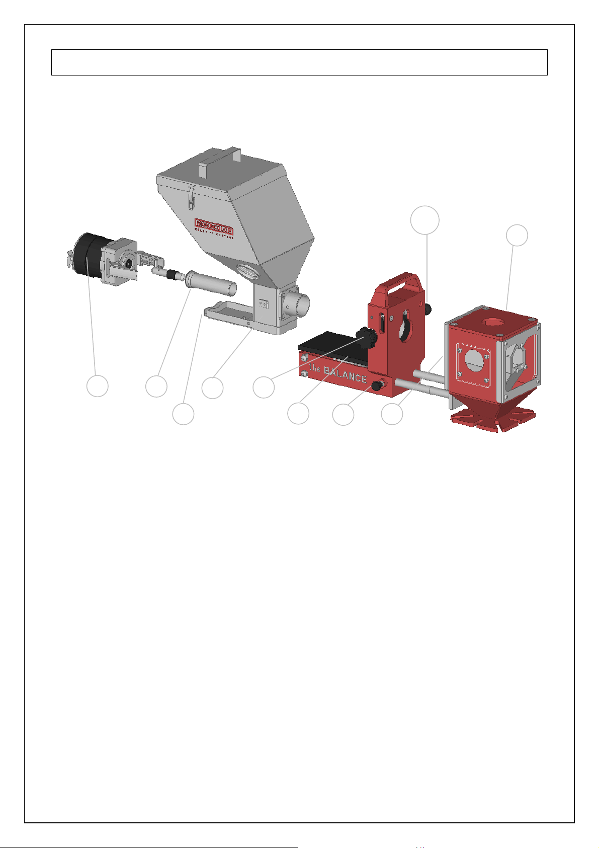
3. Overview Dosing unit ______________________________________________________________________________________3
3.1 MC-Balance Component overvie __________________________________________________________________________3
3.2 Weighing frame _________________________________________________________________________________________4
3.3 Motor and dosing system _________________________________________________________________________________4
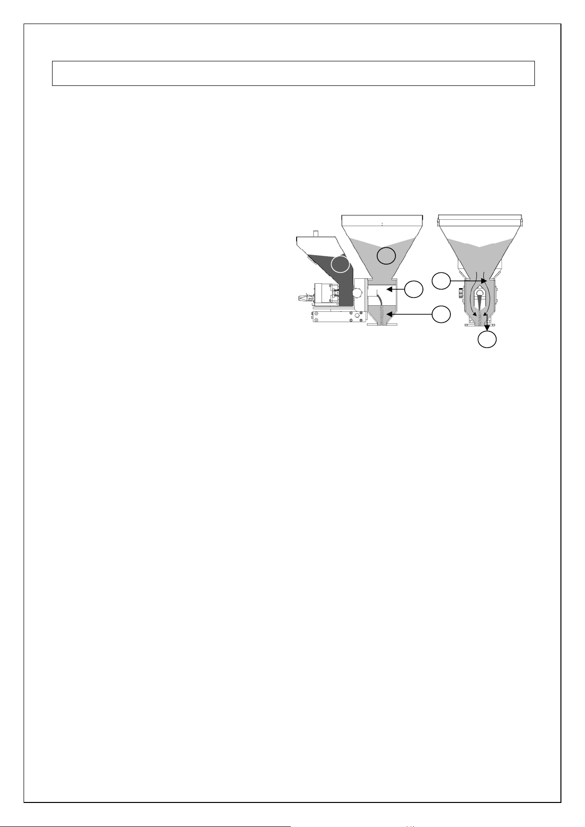
4. Metering principle _________________________________________________________________________________________5
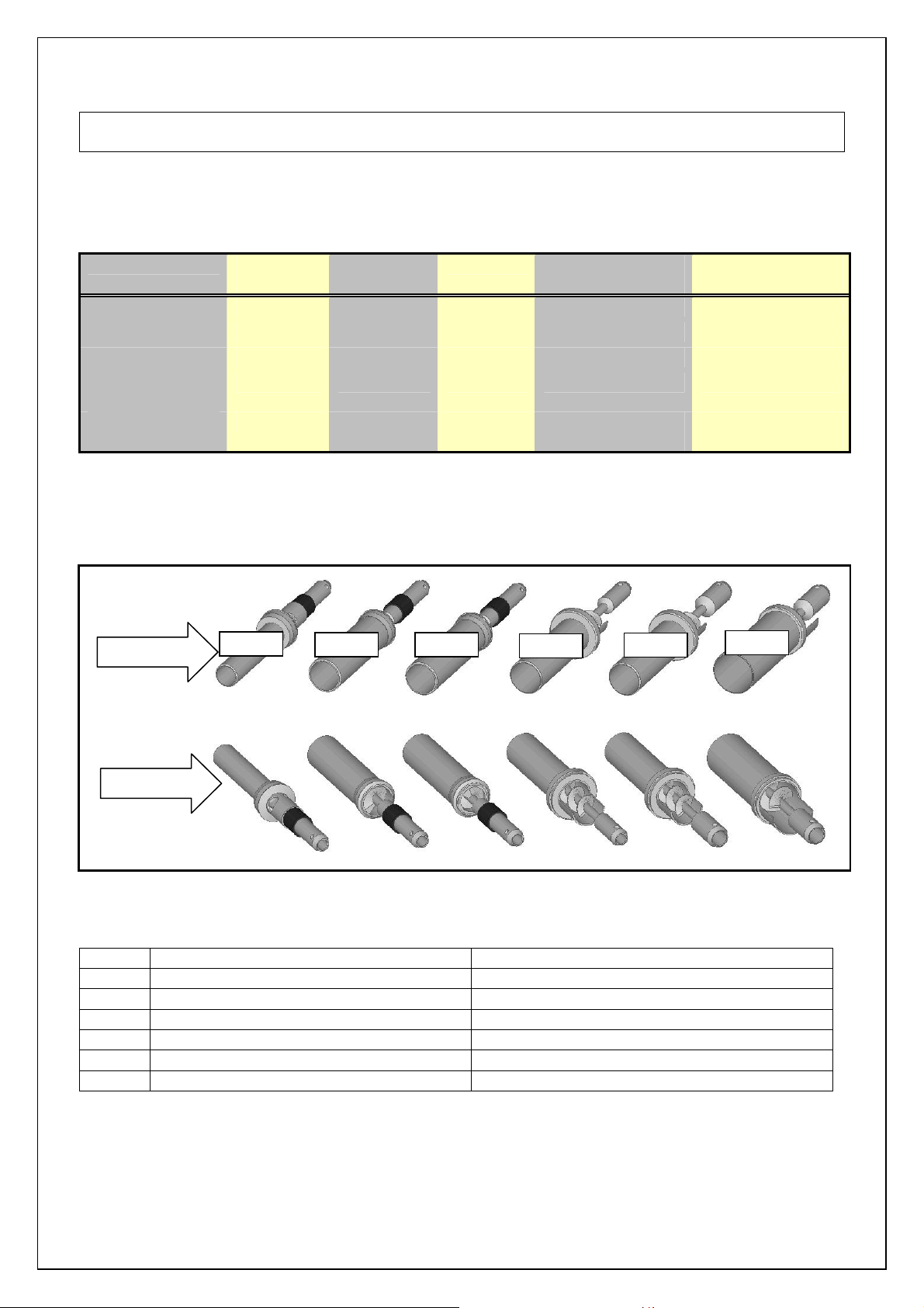
5. Dosing systems / Capacities ________________________________________________________________________________6
6. Installation _______________________________________________________________________________________________8
6.1 Transport ______________________________________________________________________________________________8
6.2 Receipt _______________________________________________________________________________________________8
6.3 Mechanical Installation ___________________________________________________________________________________8
6.4 Changing from Dosing cylinder to Feed scre _________________________________________________________________9
6.5 Electrical installation ____________________________________________________________________________________10
7. Operation _______________________________________________________________________________________________12
7.1 Navigation ____________________________________________________________________________________________12
7.2 Start up & Login________________________________________________________________________________________13
7.3 Keyboard lock _________________________________________________________________________________________14
7.4 Configuration__________________________________________________________________________________________15
7.5 Loadcell calibration _____________________________________________________________________________________21
7.6 Material Pre-calibration __________________________________________________________________________________22
7.7 Production ____________________________________________________________________________________________24
7.8 Auto/Manual regulation mode & Save data function ____________________________________________________________27
7.9 Production JOB ________________________________________________________________________________________28
7.10 Filling the hopper. _____________________________________________________________________________________29
7.11 Consumption _________________________________________________________________________________________33
7.12 Alarms ______________________________________________________________________________________________34
7.13 Files________________________________________________________________________________________________36
7.14 Event LOG___________________________________________________________________________________________37
8. System per ormance ______________________________________________________________________________________38
8.1 Reset regulation _______________________________________________________________________________________38
9. Trouble shooting _________________________________________________________________________________________39
APPENDIX A: MC-Bal. Print view __________________________________________________________________________40
APPENDIX B: MC-Bal. Wiring Diagram _____________________________________________________________________41
APPENDIX C: MC-Bal. Technical Speci ications ______________________________________________________________42
APPENDIX D: MC-Bal. Drawings General Dimensions _________________________________________________________43
APPENDIX E: MC-Bal. Decl. o Con ormity __________________________________________________________________47

MC-Balance manual
1
1. Introduction
Thank you for purchasing a Movacolor metering evice. This manual is a resse to operators
an quali ied technicians taking care of the metering of ry a itives to ensure correct use of the
Movacolor osing unit.
IMPORTANT NOTE: THIS MANUAL MUST BE READ BEFORE INSTALLING THE DOSING
UNIT. KEEP THIS MANUAL IN A PLACE ACCESSIBLE FOR ALL OPERATORS.
1.1 Symbols
Important note
Attention; safety regulations for the operator
1.2 Terms
Operator: A person charge to operate, a just, maintain an clean the machine.
Quali ied Technician: A specialize , suitable traine person authorize to execute the
installation, non-routine maintenance, or repairs requiring special
knowle ge of the machine an how it operates.

MC-Balance manual
2
2. General in ormation
2.1 Safety
The equipment is only esigne an may only be use for the osing of ry a itives.
Any use that is not in conformity with the instructions is consi ere improper an as such
frees the manufacturer from any liability regar ing amage to things an /or persons.
Before switching on the unit for the first time, ensure that the mains power voltage
applie is between 80 an 260Vac.
Always switch off the Movacolor control cabinet an isconnect the mains power plug from
electrical power before performing maintenance.
Ensure that all parts are securely fixe to the extru er or injection mol ing machine.
Dangerous voltages are present insi e the control cabinet for up to 2 minutes after it has
been switche off.
2.2 Certification
The Movacolor osing unit is esigne an pro uce in conformity with the following European
regulations:
• stan ar s for machinery (health, safety, environment)
• EMC (electromagnetic compatibility)
• VEM (safety electric material)
• 98/37/EC, Annex 1(See the eclaration of conformity, Appen ix E)
2.3 Operating environmental conditions
• The unit must be protecte against weather con itions
• Operating temperature -20 to +70 egr. C.
• Protection class: IP-50

MC-Balance manual
3
12
.
34
5
6
.
7 8
9
10
3. Overview Dosing unit
3.1 MC-Balance Component overview
1 Stepper motor
2 Dosing system (Dosing cylin er)
3 Hopper 6 ltr
4 Curle knob M10x40
5 Stan ar NST40 Neckpiece
6 Material ischarge sli e (in close position)
7 MC-Balance Loa frame
8 OPTIONAL Slide frame
9 Slide locking bolt
(locking the slide-out position)
Only supplied together ith the optional slide mechanism
10 Slide locking bar
(locking the slide-in position)
Only supplied together ith the optional slide mechanism

MC-Balance manual
4
3.2 Weighing frame
The black part is the weighing frame.
Do not touch this weighing rame (and dosing unit) while dosing.
It will have influence on the osing.
Do not touch the safety bolts un er the weighing platform. These are for overloa protection.
There must be some space between e safety bolts an the frame.
3.3 Motor and dosing system
There are mainly two osing systems, the osing cylin er an the fee screw.
(for more information see chapter 5)
Safety bolts (total of 4)
Balance frame
Hopper loa er tube support
Transport protection
The serial number of the motor can be foun on the
backsi e of the motor.
Motor axle:
The motor shaft is equippe with one flat si e which
fits exact in shaft of the osing cylin er.
To connect the osing cylin er just put it on the
motor axle while turning it to fin the flat si e, than
press the osing cylin er completely backwar s.

MC-Balance manual
5
Fig. 3
1. Color 2. Virgin material 3. Neckpiece 4. Dosing cylin er
4. Cover plate 5. Mixing zone 6. To pro uction machine
6
5
3
4
2
1
4. Metering principle
The Dosing Cylin er® of Movacolor combine with a very precise a justable stepper motor
ensures that the a itive output is accurate an regular. The neckpiece (a mixing chamber) is
esigne to blen the main material an the a itive homogeneously. Movacolor has on stock a
large range of machine neckpieces that usually make a prefect fit to the injection mol ing machine
or extru er. The most common mounting of the neckpiece is between the pro uction machine an
the hopper. In the figure below a cut through of the NST40 neckpiece can be seen.
Standard neckpiece
During operation, the virgin material runs from
the machine hopper through the neckpiece
into the machine. Insi e the neckpiece the
Virgin material flow is ivi e into two
streams
by the cover plate. In the space below the
cover plate, the rotating cylin er is osing
a itive.
A itive is a e irectly into the center of
the virgin material flow, just before it enters
the pro uction machine. This is a great
a vantage over metering evices that use
batch pre-mixing because pre-mixing can
actually cause material separation.
Separation of materials results in an irregular
a itive flow into the pro uction machine.

MC-Balance manual
6
5. Dosing systems / Capacities
Depen ing on the application a ifferent osing system might be nee e .
Use the following table to etermine roughly the best system for the application. For more etaile
information please contact your agent or Movacolor.
Dosing system Granular
materials
Powder
Materials
Accuracy Dosing capacity
Gram/sec.
Dosing capacity
Kg/hour
GLX YES YES ++ 0,02 to 1,6* 0,07 to 5,8*
GX YES YES + 0,2 to 5,0* 0,72 to 18,0*
HX NO YES ++ 0,01 to 1,6** 0,04 to 5,8**
A-20
Fee screw
YES YES +/- 0,5 to 20* 1,8 to 72*
A-30
Fee screw ***
YES YES +/- 2 to 50*
7,2 to 180*
Note * measure with normal granular masterbatch 0,8 kg/ m3.
Note ** measure with free flowing pow er 0,65 kg/ m3.
Note *** only available with high torque (4,5 Amp) stepper motor
Which type o dosing system do I need with which neckpiece?
TYPE CODE FOR STANDARD NECKPIECE CODE FOR WATERCOOLED NECKPIECE
GLX GLX GLXC
GX GX GXC
HX HX HXC
A20LT A20 A20C
A20HT
A20HT A20HTC
A30HT
A30 A30C
Front si e view
GLX
Back si e view
A20
LT
A20
HT
A
3
0
HT
GX
HX

MC-Balance manual
7
All Movacolor osing units are stan ar equippe with the stepper motor 2A (LT), in case of using
the fee screw A30 the stepper motor 4,5A (HT) will be supplie . Also a screw A20 can be
connecte to the HT motor.
Do not select the HT motor if LT motor is connecte . This will amage the motor.
If LT motor is selecte an HT motor is connecte there will be less motor torque an this can
influence the osing.
The controller of the osing unit makes a istinction between two groups of materials, normal
granules an micro granules. To etermine the kin of material in your application use the
escription below.
* For other sizes contact Movacolor.
The actual capacity of the osing system epen s on:
• The volume weight of the material (bulk density)
• The specific weight of the material (specific density)
• The granular shape of the material
• The granule size
• The surface structure of the material
Granular material can be normal or micro. The granular material an pow er material has to be
free flowing, non-static an not sticky.
Stepper motor 2A
(LT)
Stepper motor 4,5A
(HT)
Normal Granules:
(NG)
Micro
/ Mini
Granules:
(MG)
The term Micro/Mini Granules also
inclu es free flowing pow er.
Ø < 4 mm L < 4 mm *
Ø < ø2,5 mm L < 3 mm *
L
ø
L
ø
Material types

MC-Balance manual
8
Take out the win ow in
a 45° angle for easy
cleaning.
Dismountable top
flange for easy
machining.
Barrel
Horizontally levele
(Water levele )
Curle knob
Main material
hopper
90°
Hopper
assembly
Transport
protection
6. Installation
.1 Transport
To protect the Movacolor unit against amage uring transport, the unit is packe in a car boar
box fille with polyurethane foam. Delivery terms are Ex-Works Sneek, The Netherlan s. Buyer is
responsible for the transport. Movacolor cannot be hol liable for any amage uring transport.
.2 Receipt
Check the unit thoroughly upon receipt. Pass any remarks to the local agent or Movacolor within 8
ays upon receipt of goo s.
.3 Mechanical Installation
Most mechanical parts are pre-assemble , making installation quick an simple.
1. When installing a foreign main material
hopper on top of the neckpiece, the top
lange of the NST40 neckpiece nee to be
a apte . The li of the neckpiece can be
ismounte for easy machining.
2. -Install the neckpiece irectly on top of the
entrance of the pro uction machine.
-Install the neckpiece in a 90-degree angle
to the machine barrel. This will optimize the
osing accuracy in relation to vibrations of
the pro uction machine.
-Make sure that the complete unit is mounte
horizontally leveled an fixe securely.
-Assure proper groun ing to control cabinet,
neckpiece an osing unit
3. Remove the transport
protection (at the
bottom of the
loa frame) before
placing the hopper
assembly.
This is just the pin on
the flexible chain, o
not ismount the stainless steel plate!
4. Connect the hopper assembly to the
neckpiece by turning the curled knob
clockwise. Make sure that the curle knob is
tightene firmly.
5. Mount the controller vibration free an
conform specifie temperatures.
Install the neckpiece
in a
90-degree angle to the
machine barrel.
As shown in the picture.

MC-Balance manual
9
.4 Changing from Dosing cylinder to Feed screw
In relation to the maximum capacity of the osing cylin er it might be necessary to change from
osing cylin er to fee screw. As istinction from the osing cylin er the fee screw system is
consisting of a rotating screw in a non-rotating tube.
To install the fee screw perform to following steps:
1. Detach the motor quick release clamps an take out the motor from the hopper.
2. Dismount the neckpiece connection flange (1) by removing 4 socket-hea screws.
3. For use with a osing cylin er the neckpiece connection flange (1) is equippe with a ball
bearing. When using a fee screw system the ball bearing must be taken out. The metal ring
(2) which is fixe on the fee screw tube fits irectly on the neckpiece connection flange.
4. Dismount the osing cylin er (3) an mount the screw (4) with the M5 bolt.
5. Place back the motor + screw by closing the motor quick release clamps.
For cleaning the motor + screw can be easily be taken out.
POSSIBLE COMBINATIONS
1
3
4
2
Art.nr:H000010
In
clu e seal
Art.nr:H000014
Inclu e ball bearing
Art.nr:H000002
G / GL /
H
GX / GLX / HX
A20

MC-Balance manual
10
BALL BEARING
For cleaning of the ball bearing use a ry piece of textile or a smooth ry toothbrush to remove
the ust or moisture an foreign particles that stick.
Following points have effect on the lifetime of the ball bearing:
o Abrasive materials
o Temperature
o Dusty / fine pow er materials
.5 Electrical installation
The MC-Balance controller is stan ar equippe with 3 connections:
• Mains power cable
Before switching on the unit for the first time, ensure the mains power voltage being
applie is between 80 an 260Vac.
• Input cable
• Motor cable
Be aware that the cables will not be influence by external circumstances as electromagnetic
fiel s!
Mount the controller on a place which is vibrations free an not hot!.
Optional are:
• Alarm flash light, complete with cable
• Compresse air solenoi valve complete with cable (for automatic hopper loa er)

MC-Balance manual
11
APPENDIX A SHOWS THE PRINT VIEW WHICH WILL BE EXPLAINED BELOW
1) PROCESSOR BOARD
The processor boar is the heart of the controller.
This boar must be fixe securely on the mainboar .
There’s also a label on it with the Mac-a ress. This is the ID of the networkcar .
This a ress can also be seen in the startup screen.
2) EXTERNAL TERMINAL CONNECTION
This connector will be use when using an external terminal (Shiel e cable max. 10 meter)
3) CONNECTION TO PC OR NETWORK
This connection (Ethernet) will be use when using a PC or network.
Max. length of the UTP network cable, type RJ45 (Cat. 5) is 100 meter between 2
network points.
4) INPUTS
Start input
The MC-Balance nee s an input signal from the pro uction machine in or er to operate.
Three ifferent input signals can be use to control the MC-Balance:
• Potential free start input.
• Potential (24 V c) start input
• Tacho (0-30 V c) start input
5) MOTOR
The MC-Balance can control 2 motor types:
• LT (low torque) stan ar motor for normal osing
• HT (high torque) motor for high output osing
(See chapter 5 for more etails an wiring iagram for electrical connections, appen ix C)
6) OUTPUTS
The MC-Balance has following outputs available:
• [clamp 24-25] Valve output for hopper loa er, (Soli state 24VDC/0.5 A)
• [clamp 22-23] Warning output (Soli state 24VDC/0.5 A)
• [clamp 26-27] Potential free relay (normally open) output for Alarm (max. 230Vac/30V c, 5A)
• [clamp 28-29] Potential free relay (normally open) output for Running contact
(max. 230Vac/30V c, 5A). This contact will be use to show that the motor is running.
The maximum total output power may be 12 Watt (Valve output + alarm output together max. 0,5A)
(See wiring iagram appen ix C for electrical connections)
7) POWER SUPPLY
The MC-Balance will operate with a voltage from 80 VAC to 260 VAC, 50 an 60 Hz
by integrate automatic voltage selector.
(See wiring iagram appen ix C for electrical connections)

MC-Balance manual
12
Inpu
t LED is
lighted
:
input signal is ON
Alarm LED is lighted
:
alarm / warning
Enter / scroll / exit
MENU
Start LED blinking
:
motor is stan by / waiting for start signal
Start LED lighted:
motor is running
Arrow up / down
:
Scroll through parameters
Arrow le t / right:
Scroll through menus /
settings
Alphanumerical
buttons:
Set values /
escriptions
Enter:
Confirm settings /
Pick up a JOB
Start:
Start unit
Stop:
Stop unit
Loa cell
External communication /
Network
Mains power switch: ON / OFF
Mains power cable
Start input cable
Motor cable Valve output
for hopper loa er
Output for:
-Alarm
-Warning
-Running
7. Operation
7.1 Navigation

MC-Balance manual
13
7.2 Start up & Login
Directly after switching on the mains power of the MC-Balance, the software versions will be
isplaye . In the first screen the software version of the terminal will be shown.
After a few secon s the secon screen appears for 10 secon s.
Vx.x = user software version Vx.x
DE-Vx.x = Language version Vx.x
Stan ar language is English
DE means that the a itional language is DEUTSCH (German).
BL Vx.x = bootloa er software (firmware) Vx.x
Mac a ress = ID a ress of the network car
The MC-Balance controller has three user levels:
1. Operator 2. Tooling 3. Supervisor
The functions which are accessible per user level is shown in the table below.
The operator level is the lowest level, only the important settings for pro uction can be one. The
rest of the settings / menu’s are invisible or locke .
For changing to another user level, enter the LOGIN menu an enter the passwor (4 numerals)
an confirm. The passwor s for the Tooling an Supervisor user levels can be efine by the
supervisor in the CONFIGURATION <menu>.
USER LEVEL
Can be change in LOGIN menu.
MENU TITLE: FUNCTION: SUPERVISOR
Default co e
2222
TOOLING
Default co e
1111
OPERATOR
Default co e
0000
[LOGIN] To enter the ifferent user levels. YES YES YES
[CONFIGURATION] To configure the osing system. YES NO NO
[PRODUCTION] To o the pro uction settings.
*In OPERATOR level jobs an materials are rea only. YES YES YES*
[FILES] To look for, rename or elete jobs an curves YES NO NO
[HOPPER LOADER] To o the hopper loa er settings,
only visible when a hopper loa er is selecte . YES YES YES
[CALIBRATION] To make material calibrations, only visible when control
mo e is set to GRAVI (Gravimetric). YES YES NO
[LOAD CELL] To calibrate the loa cell. YES NO NO
[WEIGHT CHECK] To check the hopper or object weight. YES YES NO
[CONSUMPTION] View of the total quantity of material ose by the
MC-Balance. YES YES NO
[ALARMS] View of the alarm history
*In TOOLING level the alarm configuration is invisible. YES YES* NO
[EVENT LOG] The history of events or settings will be logge in this
menu. YES NO NO
Recommen e to note the passwor s!
Forgot your supervisor passwor , enter the overall supervisor passwor 1689.
When entering a wrong passwor the user level will be set automatically to operator level.
Movacolor Terminal
Version x.xx
Date: January 2005
Movacolor McBalance
Color in Control
Vx.x
DE-Vx.x
MENU to continue
BL Vx.x
Mac-00:12:EC:xx:xx:xx

MC-Balance manual
14
7.3 Keyboard lock
The keyboar lock function…
• is accessible in the [ LOGIN ] menu.
• can only be activate an eactivate with the SUPERVISOR login co e.
• is only full functional in OPERATOR an TOOLING user level.
For example: if the “Start user” setting is configure to “Supervisor”, the keyboar lock is
eactivate as soon as the controller is switche OFF an ON.
The following screen will appear when the [LOGIN] menu is entere :
Press or to select Locked or Unlocked an press Enter to
confirm. When Locked selecte the unit will automatic be set to
OPERATOR level.
This screen will appear when a user is trying to change settings while
the keyboar is locke . To unlock the supervisor co e nee s to be
entere in the LOGIN menu.
With the keyboar lock ON it is still possible to…
• Shift between the LOGIN, PRODUCTION an HOPPERLOADER menu.
• To START an STOP the osing unit.
For further information check the Start up & LOGIN paragraph (7.2).
USER LEVEL
Enter the password to set
the user level.
Level : SUPERVISOR
Key lock: Unlocked/Locked
MESSAGE
Keyboard locked !
To unlock enter
supervisor code.
MENU to continue

MC-Balance manual
15
7.4 Configuration
For initial setup the MC-Balance controller nee s to be configure in the CONFIGURATION
menu once. Depen ing on the configuration, some settings will be invisible in case they are not
relevant.
Highlighte Parameters are factory settings.
Language : ENG / DE
Motor type : LT / HT
Cylinder type : GX / GLX / HX / A20 / A30
Material type : NORMAL / MICRO
Cal dev. : 5,0 %
Control mode : GRAVI / RPM
Prod. Mode : INJ / EXT
Input mode : Timer / Relay / Tacho
Fill. System : NO / ME / MV / EX
└ EX HH level : 3500 gr.
└ EX H level : 2500 gr.
└ Filling start : 800 gr.
Hopper empty : 700 gr.
Deviationalarm : 25 %
Jobs enabled : NO / YES
Auto start : NO / YES
Master reset : NONE / ALARM / MATER / JOBS / ALL
IP : xxx . xxx . xxx . xxx (For example: 192.168.001.001)
Name : xxxxxxxxxxxxxx
Start user : Operator / Tooling / Supervisor
Tooling passw. : xxxx 1111
Supervisor passw. : xxxx 2222
Conversion : Metric / Imp / kg/h
Full scale : xx.xx kg
Modbus unit : 1-231
Date : ( / mm / yy)
Time : (hh / mm / ss)
Configuration: Language
Stan ar language is English. On request also ifferent languages are available.
Configuration: Motor type
LT is Low Torque motor an HT is High Torque motor (see chapter 5 for more information)
Do not select HT motor if LT motor is connecte .
Configuration: Cylinder type
Type of osing cylin er / fee screw (see chapter 5 for more information)
Configuration: Material type
Type of material, normal granules (NORMAL) an micro granules (MICRO).
(see chapter 5 for more information)
Configuration: Cal dev.
The maximum allowe eviation from the Calibration Setpoint can be set with this
Parameter. (For more information see chapter 7.6)

MC-Balance manual
16
Configuration: Control mode
(GRAVI) Gravimetric mo e or (RPM) Rotating mo e
• Gravimetric mo e is set as efault an operates on the base of loss-in-weight principle.
The output is measure an regulate continuously by controlling the motor spee .
• Volumetric mo e (RPM) can be use if no automatic fee back of the weight is require .
The weighing will not function in this mo e an also the automatic hopper loa er function will
not work.
Configuration: Prod. mode
Pro uction mo e
Selection of the machine on which the MC-Balance is place .
(EXT) extru er or (INJ) injection mol ing
Configuration: Input mode
Type of input signal. Relay, Timer or Tacho
Timer mo e is the stan ar setting for Injection mol ing.
Input mo e is not visible in RPM pro . Mo e. (Timer is use automatically)
For INJ in timer mo e the start pulse shoul be min. 0,2 secon s.
For INJ in relay mo e the start signal shoul be as long as the osing time.
If INJ-Relay is selecte the osing machine will follow the machine relay time.
The controller will filter small changes out so that the regulation is not being influence .
Big changes will be followe .
The screen shows the real machine relay time.
Input (start) signal
The MC-Balance nee s an input signal from the pro uction machine in or er to operate.
Three ifferent input signals can be use to control the MC-Balance.
1.) A potential free relay contact.
Use the white an brown wire for the potential free contact.
2.) A relay signal 24 Volt DC*.
In case of a powere relay signal connect the white wire to +24 VDC an the yellow wire to
the 0 VDC.
* Note potential contact
Guarantee OFF: 0-8VDC
Guarantee ON: 18-30VDC
3.) A tacho signal up to 30 Volt DC.
This is use when the MC-Balance nee s to be connecte to an extru er that has a tacho
generator that pro uces a voltage linear to the extru er spee . When using a tacho
generator signal, make a connection between the white an brown wire. It will function as a
start signal. Connect green to + VDC an yellow to the - si e of the generator.
EXT INJ
timer x x
relay x x x
tacho x x
GRAVI
RPM
GRAVI
RPM

MC-Balance manual
17
The maximum voltage that can be applie to the MC-Balance is 30 VDC. The tacho voltage has to
be re uce to 30 VDC if the tacho generator has a higher voltage output than 30 VDC at the
maximum extru er output capacity. See the iagram below.
Rx (kilo-Ohm) = (2,684 x (Max. tacho output VDC – 5)) – 66
If the extru er stops when connecte to the metering unit, an isolate signal converter is nee e .
Contact your agent or Movacolor for more information.
Tacho function
The tacho function is only available in extrusion mo e.
This function can be use with extrusion when it is necessary that the osing rate is automatically
a juste to the extru er spee . In tacho mo e an input voltage is linke to a osing spee setting.
If the extru er spee changes, the tacho input voltage an spee of the osing unit will change
accor ingly.
A linear correlation between extru er spee (tacho input signal) an the nee e osing spee is
assume . See graph.
The tacho function can be set in the PRODUCTION screen.
Tacho can be set automatically an manually:
Max tacho: 0.0V
Set tacho: NO / YES
Highlighte Parameters are factory settings.
Input
connection
Resistor (
Rx
)
kOhm
Green wire +
Tacho
generator
EXTRUDER
Yellow wire -
17
8
Tacho input voltage (VDC)
Spee (RPM)
Tacho graph
(Example)
Other manuals for MC-BALANCE
1
Table of contents
Other Movacolor Measuring Instrument manuals