moyno Version 3 User manual

SERVICE MANUAL
MOYNO®
Annihilator™
Series 3

Table of Contents
1-1. INTRODUCTION..................................................................................................................................1
1-2. GENERAL.............................................................................................................................1
1-3. NAMEPLATE DATA..............................................................................................................1
1-4. Model Number............................................................................................................1
1-5. Frame Designation .....................................................................................................1
1-6. Trim Code...................................................................................................................2
1-7. Equipment Description................................................................................................2
1-8. Grinder Unit................................................................................................................2
1-9. Motor ..........................................................................................................................2
1-10. Reducer......................................................................................................................2
2-1. INSTALLATION...................................................................................................................................2
2-2. GENERAL.............................................................................................................................2
2-3. Piping ...................................................................................................................................2
2-4. Foundation ............................................................................................................................2
2-5. Motor Controls ......................................................................................................................2
3-1. OPERATION ...................................................................................................................................3
3-2. INITIAL CHECK/START-UP..................................................................................................3
4.1. MAINTENANCE ...................................................................................................................................3
4-2. LUBRICATION......................................................................................................................3
4-3. Motor Bearings.............................................................................................................3
4-4. Gear Reducer...............................................................................................................3
4-5. Cartridge Assembly......................................................................................................3
4-6. DISASSEMBLY...................................................................................................................3
4-7. Disconnect Grinder.....................................................................................................3
4-8. Cartridge Replacement...............................................................................................4
4-9. Motor Removal………………………………………………………………………………4
4-10. Gear Reducer Removal..............................................................................................4
4-11. Cartridge Disassembly................................................................................................4
4-12. INSPECTION.......................................................................................................................4
4-13. ASSEMBLY.........................................................................................................................5
4-14. Seal Assembly............................................................................................................5
4-15. Cartridge Assembly………………………………………………………………………….5
4-16. Reducer/Motor Assembly...........................................................................................6
4-17. Torque Guidelines Chart ............................................................................................6
4-18. STORAGE...........................................................................................................................7
4-19. Short-Term Storage....................................................................................................7
4-20. Long-Term Storage ....................................................................................................7
4-21. Hardware List......................................................................................................................8
4-22. Parts List .............................................................................................................................9
Parts List continued………………………………………………………………………………..10
Flanged Reference ………………………………………………………………………………..11
Exploded View...................................................................................................................12 & 13

SERVICE MANUAL
Moyno®Annihilator™
Series 3
1-1. INTRODUCTION
1-2. GENERAL
The Moyno®Annihilator, twin shaft grinder, is a rugged and
reliable grinder designed to efficiently reduce the size of large
solids typically encountered in raw wastewater, primary
thickened sludge, digested sludge, slaughterhouse waste,
and pulp and paper recycling. The grinder has been tested to
assure consistent performance in the most difficult of
applications. It represents the next generation of the world’s
most reliable grinder.
The Moyno®twin Annihilator utilizes an improved version of
the counter-rotating shaft design that has proven to be a
reliable method of shredding large solids (pieces of wood,
plastic bottles, cloth towels and rags, and aluminum cans,
etc.) into smaller pieces. The slow rotating shafts are ideal
for shredding solids that are large and dense. By utilizing a
slow speed gear motor, the cutters have high torque
capability and low impact while severing debris.
The Moyno Annihilator is designed with cutting teeth on both
the cutters and spacer cutters which increases the cutting
capability of rags over other twin shaft grinders and
eliminates the greatest cause of failure – that of stringy
material wrapping around the spacers.
The Moyno Annihilator product line is modular in concept
allowing for optimal utilization of cutters for channel or in-line
units to meet the requirements of the application. The cutter
cartridge assembly allows for the removal and replacement
of the entire cutting assembly as a single unit. The cutter
cartridges consist of a top and bottom housing, side rails,
seal cartridges, hex shafts, cutters, and spacer cutters
(Figure 1-1.).
The complete Annihilator unit consists of the cutter cartridge
assembly, reducer adapter, gearbox, motor (Figure 1-2).
Figure 1-2. Complete unit.
1-3. NAMEPLATE DATA
The grinder nameplate, located on the top housing, contains
important information relating to the operation and servicing
of the grinder. This information includes the model and serial
numbers (see Figure 1-3.). The grinder model number must
be used for reference when ordering a replacement cartridge
or spare parts.
Model:
M06C3 CE5R7R
MFG Serial: ASXXXXXX
Date: 10/04
Figure 1-3. Typical nameplate data
1-4. Model Number. The grinder model number consists of
two component parts: Frame Designation and a Trim Code.
A typical model number, for example, might be M06F3
CE7R5R as shown on the nameplate in Figure 1-3.
1-5. Frame Designation. The five characters in the frame
designation describe the particular combination of
construction and cutter height.
The first character in the frame designation, always a letter,
indicates the construction as either a complete unit (M) or
replacement cartridge (C).
Section: MOYNO®Annihilator™
Page: 1
Date: December 2007
Figure 1-1. Cutter cartridge.

The second and third characters, always numbers, indicate
either the flange size or cutter stack height.
The fourth character is a letter indicating whether it’s a flange
unit (F) or channel unit (C). If the fourth character indicates a
flange unit, the second and third characters indicate the
flange size in inches. If the fourth character indicates a
channel unit, the second and third characters indicate the
cutter stack height.
The fifth character indicates the series of the unit:
Series 2 -- 2½” hex shaft
Series 3 – 2” hex shaft, design after July 2003
Series 4 – 2” hex shaft, one-piece flange housing design
1-6. Trim Code. Also included in the Model Number is the
six character Trim Code which is used to identify grinder
construction.
The first letter identifies the materials of construction.
C -- Cast iron, ductile iron, and alloy steel
S -- Stainless steel
X -- Special
The second letter identifies the type of drive utilized.
E -- Electric motor and gear box
S -- Submergible motor and gear box
H -- Hydraulic motor with power package
X -- Special
The third and fourth characters identify the type of cutters on
the drive shaft:
5R – 5 tooth reversible
7R – 7 tooth reversible
7C – 7 tooth cam
11C – 11 tooth cam
The fifth and sixth characters identify the type of cutters on
the idler shaft:
5R – 5 tooth reversible
7R – 7 tooth reversible
7C – 7 tooth cam
11C – 11 tooth cam
If the trim code of your grinder is other than the variations
listed above contact your nearest Moyno representative for
clarification. Do not modify your grinder with any variations
unless you have determined that it is compatible with your
application.
1.7 EQUIPMENT DESCRIPTION
1-8. Grinder Unit. The Moyno Annihilator is a motor driven,
double shaft design stacked with intermeshing cutters and
spacer cutters positioned on the shafts. The shafts are
constructed of a hexagonal, 4140 steel and counter-rotate at
60 and 36 RPM. The shafts contain intermeshing cutters and
spacer cutters.
The Moyno Annihilator series 1 and 3 product lines, consist
of seven channel models ranging from 8 to 60 inch high
cutting chamber, and five flanged, in-line models from 4 to
12 inch flanged.
1-9. Motor. Each Moyno Annihilator is equipped with a
motor:
•TEFC or Explosion proof design
•3 or 5 HP
Page 2
•1725 RPM, 3/60/230/460V
•Baldor or Moyno choice
1-10. Reducer. Each Moyno Annihilator is equipped with a
cycloidal speed reducer:
•29:1 ratio
•60 RPM output
•Sumitomo or Moyno choice
•Model 6125Y…3HP and 5 HP
Note: See manufacturer’s service manuals for more
details.
2-1. INSTALLATION
2-2. GENERAL
Moyno Annihilators are lubricated and tested at the factory
prior to shipment and require minimum pre-start up
maintenance.
Accessibility to the grinder and adequate clearance should
be a prime consideration in any installation. Enough space
should surround the unit so that maintenance can be carried
out with ease.
2-3. Piping. For in-line flanged units, piping should generally
be the same size as the flange and supported, not applying
vertical or horizontal forces to the grinder flanges. Be sure
to mount the unit in the piping in the proper flow
direction. Check the flow direction arrow on the grinder.
2-4. FOUNDATION
Flanged units should be mounted on a concrete base. The
base should be 4-8 inches wider then the Grinder base.
Anchor bolts are not required to attach the grinder to the
concrete base.
Check the base surface with a carpenter’s level and shim
under the grinder at the places necessary to make the unit
level. Care should be exercised to ensure the grinder
flanges are mounted in line and without piping strain.
Channel units should be mounted in a suitable framework for
support.
2-5. Motor Controls. To protect the Moyno Annihilator from
potential damage, all Grinder units should be wired to a
Moyno control panel. In the event an unusually difficult
material engage the cutting chamber, the automatic controller
senses the overload and reverses the rotation of the cutters
to clear the object. The controller then returns the Grinder to
the forward direction of rotation. It is highly recommended
that this type of overload protection be provided for all
grinders to prevent damage to the unit.
Caution:
•Cutters and spacer cutters are very sharp. Keep
personnel clear of cutting chamber.
•Do not lift heavy equipment over the head of
personnel.
•Electrical hazard…Be sure power is off and locked
out.

3-1. OPERATION
3-2. INITIAL CHECK / START-UP
CHECKLIST
Before putting the grinder into operation, the following items
should be checked to ensure that each piece of equipment is
installed correctly:
•Recheck for proper line voltage connections at the
control panel and control transformer. Check the
transformer for continuity.
•Set the programmed controller (inside the door of the
Annihilator control panel) to the number of attempts
desired to clear jams or overloads before automatic
shutdown. The programmed controller is normally set at
3 reversals when shipped from the factory.
•Energize the incoming power lines by closing the
disconnect device. The amber light [“POWER ON”]
illuminates, indicating power is available to the control
circuitry.
•Turn the Selector Switch to the “LOCAL” position.
Depress the “Start” pushbutton. The blue light
[“GRINDER ENABLED”] will illuminate to indicate that
the control circuits are energized and the green light
[“GRINDER RUNNING”] will illuminate indicating the
drive motor should be operating.
•Check the direction of cutter rotation.
Reversible cutters denoted as 5R or 7R, can operate in
either direction of rotation. The cutters should rotate with the
teeth rotating inward, towards one another on the inlet side of
the flow. If the motor is rotating in the reverse direction,
disconnect the power to the control panel.
CAUTION: Using a volt meter double-check that the
incoming power lines L1, L2, and L3, as well as the
motor lines T1, T2, and T3 in the control panel all
indicate that the power is OFF.
Interchange any two of the motor leads in the control panel at
Terminal Blocks T1, T2, or T3. Do not change the
connections at the contactors. Repeat Steps 3, 4, and 5,
above.
However, cam cutters denoted as 7C or 11C, can only
operate in one direction of rotation. The cutters should also
rotate with the teeth rotating inward, towards one another on
the inlet side of the flow. With cam cutters you must first
install the unit in the piping in the correct flow orientation.
Interchange motor leads if the cutter direction is wrong.
•To test the reversing function of the programmed
controller, it is not necessary to attempt to physically jam
the grinder. Simply depress the “Test” button on the
controller inside the door of the panel. Each activation of
the “Test” pushbutton will initiate a reversal of the
grinder.
Page 3
Figure 3-1. Cutters rotating inward.
4-1. MAINTENANCE
Note: In this section, a number or a letter in parentheses will
follow the first reference to each grinder part ( ). These
numbers and letters are those used to identify the grinder
parts and hardware items in the section view diagram.
4-2. LUBRICATION
4-3. Motor Bearings. The motor bearings are lubricated at
the factory and will need to be re-lubricated after 12,000
hours of operation. See your motor maintenance manual for
details.
4-4. Gear Reducer. The gear reducer is filled with grease at
the factory and will require re-lubrication every 3-5 years.
See your reducer maintenance manual for details.
4-5. Cartridge Assembly. The grinder top housing is half
full of ACG-2 grease prior to shipment and is ready for
operation. The top housing contains two gears that only
need to be re-lubricated when the assembly is being
repaired. You can re-lubricate the housing via the pressure
release grease fitting (35). The pressure release grease
fitting is pre-set at 10 psi. At pressures greater than 10 psi,
the grease will be observed exiting the grease fitting via the
bypass. This feature prevents over packing the bearings with
grease and is available through Alamite.
The bottom bearing housing is sealed and gasketed and
requires no lubrication.
List of Lubricants (or Equivalents)
Motor Bearings See Mfg
Recommendation
Gear Reducer See Mfg
Recommendation
Top Housing ACG-2 (Dubois
Chemical)
4-6. DISASSEMBLY
Note: The following instructions cover grinder disassembly.
4-7. Disconnect Grinder
1. Flush the grinder (preferably with clean water) to remove
all debris from the unit.
2. Shut off grinder.

3. Close suction and discharge valves.
4. Disconnect power source.
Caution: Electrical hazard…Be sure power is off
and locked out.
5. Drain any fluid in grinder.
4-8. Cartridge Replacement
Note: The following instructions cover the removal of the
motor and gear reducer as an assembly to facilitate
replacement of the grinding cartridge.
1. Secure the motor/reducer with a nylon sling and support
with a hoist.
2. Remove cap screws connecting the reducer adapter (42)
to the housing adapter (9). Remove the reducer adapter,
reducer, and motor by lifting up with the hoist. Be
careful not to allow the assembly to tip over.
3. Loosen the jaw coupling (43) set screw and remove the
coupling half and key from the drive shaft (7).
4. Flanged Models….M04F3, M06F3, M08F3, M1031, and
M12F3
a. Remove the bolts and lock washers that connect the
flange housings (41) to the inlet and outlet flanges
of the pipe.
b. Remove the cutter cartridge / flange housing
assembly from the piping.
c. Remove the cap screws and lock washers
connecting the flange housings to the cutter
cartridge. Remove the gaskets (40).
5. Remove and replace the cutter cartridge with a new or
rebuilt cartridge from an Authorized Moyno
Representative.
4-9. Motor Removal
The grinder may remain in line during motor removal and
replacement.
Open and tag power disconnect in the control panel.
Disconnect and tag motor leads in the motor conduit box.
Remove the bolts connecting the motor (45) to the gear
reducer (44). Some gentle prying may be necessary to
remove the motor from the reducer.
Remove the key from the motor drive shaft.
4-10. Gear Reducer Removal
1. Remove the bolts connecting the gear reducer to the
reducer adapter (42). Pry the gear reducer off the
reducer adapter.
2. Loosen the jaw coupling (43) set screw and remove the
coupling and key from the reducer shaft.
Page 4
3. Remove cap screws connecting the reducer adapter (42)
to the housing adapter (9). Remove the reducer
adapter.
4-11. Cartridge Disassembly
1. Remove the socket head screws connecting the bottom
cover (5) to the bottom housing (2) and remove the
cover and gasket (3).
2. While holding the jaw coupling on the drive shaft,
remove both castle nuts (16) and washers (15) from the
drive and idler shafts.
3. Loosen the jaw coupling (43) set screw and remove the
coupling and key from the drive shaft (7).
4. Find a way to support the assembly upside down on the
work bench. 4 X 4 Inch blocks can be placed on either
side of the driveshaft in order to accomplish this.
5. Remove the hex screws connecting the side rails (4) to
the top and bottom housings. Remove both side rails
and gaskets (37).
6. Remove the bottom housing (2) from the drive and idler
shafts.
7. Remove the butt screws and washers holding the seal
cartridge in the bottomtop housing. Gently press both
cartridges out of their bores and remove the two spacers
(32).
8. Remove the excluder plates (19), cutters (10), and
spacer cutters (11) from both shafts. Be careful
removing the cutters and spacer cutters because
they are very sharp.
9. Turn assembly on its side.
10. Remove the socket head screws connecting the housing
adapter to the top housing (2). Remove the gasket (3)
and clean grease from the top housing.
11. Remove the retaining rings (31) from both the drive shaft
(7) and idler shaft (6).
12. Remove both gears (12, 13) and keys (30) from the
shafts.
13. Pull both shafts from the top housing. Remove the
excluder plates.
14. Remove the butt screws and washers holding the seal
cartridge in the top housing and press the seal cartridges
out of the housing.
15. Clean all parts in a suitable cleaning solvent being
careful to observe all safety precautions regarding the
use of solvent.
4-12. INSPECTION
1. Inspect all parts for wear and corrosion. Replace any
parts that worn.
2. Replace all seals, bearings, O-rings, and gaskets.

4-13. ASSEMBLY
The Moyno Annihilator is generally reassembled in the
reverse order of dismantling.
During the assembly process, cleanliness is important. To
avoid premature failure, bearings, and seal components must
be handled with care and kept clean.
4-14. Seal Assembly
The seal cartridge assembly can be purchased from Moyno
as a separate piece from the bearing and bearing sleeve for
a more economical method of rebuilding your grinder. (See
the parts list for part numbers). Follow the instructions below
for assembly.
1. Install the O-ring (24) in the ID of the seal sleeve (17).
Place the stationary portion of the seal on top of the
rotating face. Place the O-ring (23) in the OD of the seal
insert (19), push the entire assembly down on the seal
sleeve until the retaining ring groove can be seen.
Install the retaining ring (21) on the sleeve (17).
2. Carefully push the seal assembly (18,all parts mentioned
in step 1.), spring end first, onto the shaft (6 & 7). Be
careful not to damage the rubber o-rings as you slide it
onto the shaft, both I.D. and O.D.
3. Place the ball bearing (20) onto the bearing sleeve (58)
and install with bearing side first. The bearing sleeve will
bottom out against the seal sleeve, while the bearing
and seal insert should be in contact.
4. Repeat this procedure for each seal assembly.
4-15. Cartridge Assembly
1. Place the top housing (2) upside down on the work
bench and place the spacer (32) inside each bore.
Gently push two bearing / seal cartridges (seal end first)
into the bores. The ball bearing should be facing up
towards you.
2. Secure each cartridge with two butt screw and washers
(38, 39).
3. Turn the top housing so that it rests on it’s side. Place
two excluder plates (14) into position on the top of the
seal cartridge assembly.
4. Push the keyed end of both the drive and idler shafts
through the holes in the seal cartridge in the bottom
housing. Be careful not to damage the mechanical
seals.
5. Place a key (30) in the drive shaft and slide the small OD
gear (13) down over the key. Install the retaining ring
(31) in its groove above the gear.
6. Place a key (30) in the idler shaft and slide the large OD
gear (12) down over the key. You may have to turn the
shaft slightly to get the gear teeth to line up. Install the
retaining ring (31) in its groove above the gear.
7. With a hammer, tap the two spring dowels (8) into the
two counter bored holes in the top housing.
Page 5
8. Wipe a liberal amount of ACG-2 grease on and around
each gear and fill the top housing approximately half full
of grease.
9. Press the lip seal (25) into the housing adapter (9) with
the spring side down.
10. Place the housing gasket (3) on the top housing and
carefully slide the housing adapter over the drive shaft
and down on the gasket. Secure the housing adapter
with two socket head screws, two hex head screws and
four washers. The two socket head screws go in the
middle of the housing. The two hex head screw go in
the two holes on the idler shaft side of the housing.
11. Install the grease fitting (26) in the housing adapter.
12. Find a way to support the assembly upside down on the
work bench. 4 X 4 Inch blocks can be placed on either
side of the driveshaft in order to accomplish this.
13. Align both shafts so that the point of the hex is facing
toward you and perpendicular to the long edge of the
bottom housing. It does not matter which side the drive
or idler shaft is on; right or left. Please refer to the trim
code section 1-6 to identify the type of cutters to be
placed on the drive and idler shafts.
Figure 4-1
14. Each cutter and spacer cutter has only 1 of the 5 cutting
teeth radially in line with one point of the hex ID hole
(see figure 4-2). This tooth is denoted as the Assembly
Position (AP). To expedite the cutter/spacer stacking
process, all cutters and spacers should be separated
into separate piles for the drive shaft cutters, idler shaft
cutters, and spacer. Time should also be taken to
clearly mark and identify the AP for all cutters/spacers.
Figure 4-2
3
2
Shaft 1
1
6
4
5
Shaft 2
3
4
5
6
1
2

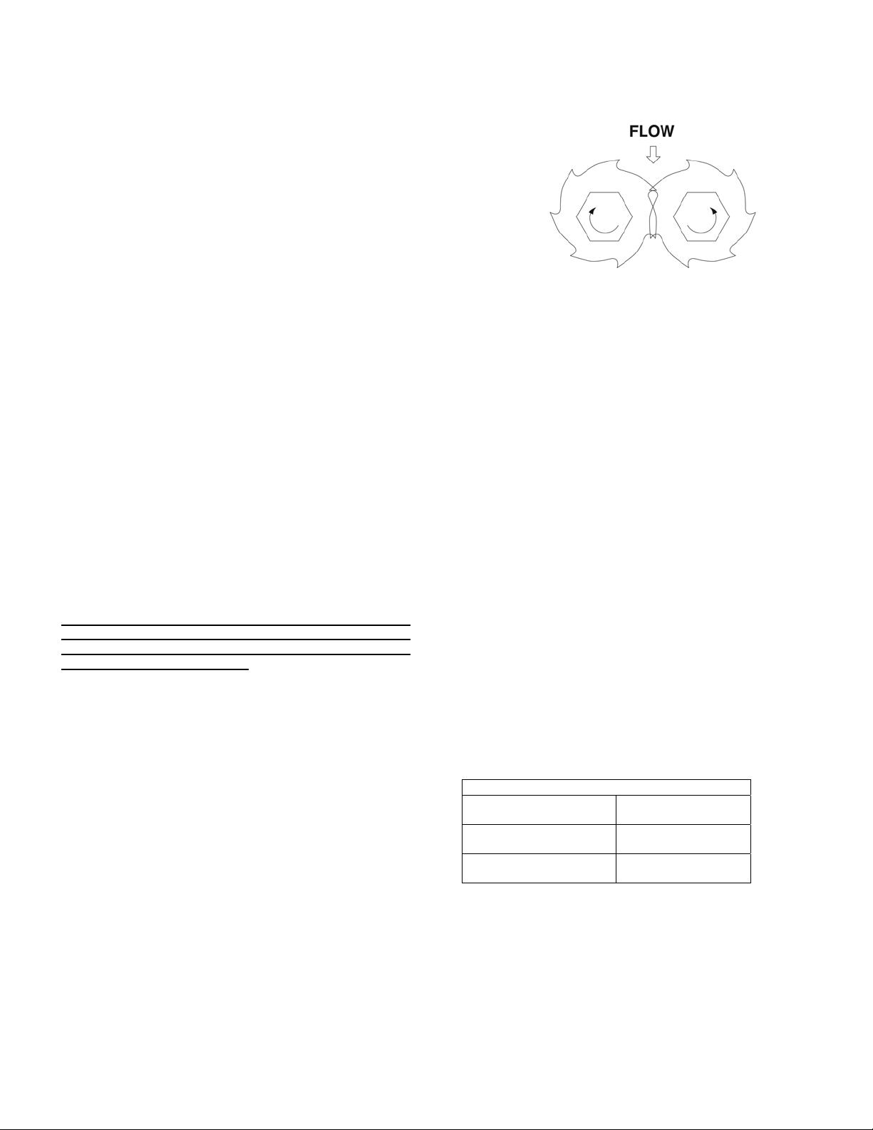
15. Place a large (L) cutter on Shaft 1 with the AP positioned
at Point 6 on the shaft 1 (See figure 4-1.). Place a small
(S) spacer cutter on Shaft 2 with the AP positioned at
Point 3.
Place a small (S) spacer cutter on Shaft 1 with the AP
positioned at Point 3, then place a large (L) cutter on
Shaft 2 with the AP positioned at Point 6.
Follow the pattern below until all cutters and spacer
cutters have been installed.
Cutters and spacer cutters are very sharp. Be careful
handling them.
Shaft 1 Shaft 2
6L 3S
3S 6L
1L 4S
4S 1L
2L 5S
5S 2L
3L 6S
6S 3L
4L 1S
1S 4L
5L 2S
2S 5L
6L 3S ÅRepeat Starts
3S 6L
Cutter and Spacer Stacking Arrangement
16. Place an excluder plate over the top of each shaft down
on top of the last cutter and spacer cutter.
17. Place the bottom housing (2) upside down on the work
bench and gently push two seal cartridges (seal end
first) into the bores. The ball bearing should be facing
you.
18. Secure each cartridge with two butt screw and washers
(38, 39).
19. Gently lower the bottom housing down over the ends of
each shaft being careful not to damage the mechanical
seals.
20. Place the flat washer and castle nut on the end of each
shaft. Tighten castle nuts approximately ¾ of the way,
leaving them loose at this point. The castle nuts are the
prevailing torque type and will have resistance the entire
way up the thread. It will be necessary to hold the shafts
while you install the nuts.
21. Carefully lay the unit down on its side. Before you
completely tighten the two castle nuts in the bottom
housing, it will be necessary to hold the drive shaft to
prevent it from turning. You can either hold the shaft by
temporarily mounting the coupling half (43) or by
carefully wedging a small piece of soft metal between
the teeth of the two gears. After you have secured the
shafts, tighten both castle nuts (70 ft-lbs).
22. Place the housing gasket (3) and bottom cover (5)
against the bottom housing and secure them with six
socket head cap screws (33).
Page 6
23. Place a side rail gasket (37) against one side of the
bottom housing and attached the side rail (4) with two
cap screws and washers (28). Leave the screws loose
at this point.
24. Slide another side rail gasket between the top housing
and side rail at the top and secure with two more cap
screws. Repeat this process on the other side and
tighten all eight screws evenly.
25. For Models….M04F3, M06F3, M08F3, M10F3, and
M12F3
1. Place the gasket (40) against one side of the
cartridge body and place a flange housing (41)
against the gasket. Secure the flange with the
screws and washer (57). Place the gasket (52) and
inspection plate (53) against the flange housing and
secure with studs, washers, and nuts (54, 56)
2. Repeat the above procedure on the other side with
the second flange housing.
4-16. Reducer / Motor Assembly
1. Slide the key (29) and coupling half (43) down on the
drive shaft and secure in place with the set screw. The
root of the coupling teeth should be lined up with the end
of the shaft.
2. Place the O-ring (46) in the groove in the housing
adapter and place the drive adapter (42) on the housing
adapter. Secure the drive adapter with four hex head
screws and washers. The two longer screws thread into
the top housing along the outside and the two shorter
screws thread into the housing adapter.
3. Slide the key (29) and coupling half (43) on the reducer
shaft and secure in place with the set screw.
4. Lower the gear reducer (44) onto the drive adapter
carefully aligning the coupling halves. Align the holes in
the flanges and install and tighten the six hex screws,
washers and nuts (49).
5. Place the key in the reducer shaft and lower the motor
(45) down onto the reducer while aligning the key and
keyway. Attach the motor to the reducer with four hex
screws and washers.
4-17. TORQUE GUIDELINES CHART
Stainless Steel Bolts Carbon Steel Bolts
Size Max
Torque Size Max
Torque
NO. 10-24 22.8 in. lb. 5/16 - 18 10 ft. lb.
1/4 – 20 75.2 in. lb. 3-/8 - 16 21.7 ft. lb
5/16 – 18 132 in. lb. ½ - 13 43.5 ft. lb.
3/8 – 16 236 in. lb. 5/8 – 11 86 ft. lb.
1/2 – 13 517 in. lb. ¾ - 10 152 ft. lb.
Note: Torque values are from the Industrial Fasteners
Institute and Craftsman Corp.

4-18. STORAGE
4-19. Short-Term Storage. Storage of 6 months or less will
not damage the grinder. However, to ensure the best
possible protection, the following is advised:
1. Store grinder inside whenever possible or cover with
some type of protective covering. Do not allow
moisture to collect around the unit.
2. See OPERATION Section before startup. Be sure all
lubricants are in good condition.
4-20. Long-Term Storage. If grinder is to be stored for up to
three years, perform the above short-term storage
procedures plus the following:
1. Apply rust inhibitor to all unpainted cast iron and
machined carbon steel surfaces.
2. Store in a dry area with dust cover.
3. Maximum temperature 120F, minimum temperature 30F.
4. Relative humidity should not exceed 60%. Provide
desiccation for moisture control above the maximum.
5. Vibration levels should not exceed 2 mils at 60 hertz.
Page 7

4-21. Hardware LIst
Your Moyno Annihilator has been designed and built to
minimize overall operating cost. All wearable parts are
replaceable. A recommended inventory of spare parts is
dependent upon the application and the importance of
continued operation.
Page 8
ITEM DESRIPTION LOCATION P/N QTY
51 HEXSCR .50-13 X 1.25, 18-8 SS MOTOR 6191552200 4
50 LCKWAH .500REG,18-8SS RED/MOT 6230012430 4
49 HEXSCR .375-16X1.50,18-8SS REDUCER 6191532240 6
48 HEXNUT .375-16,18-8SS RED/DRVADP 6140012110 6
47A HEXSCR .375-16X1.00,18-8SS DRIVE ADP 6191532160 2
36 HEXSCR .375-16X2.25,18-8SS DRIVE ADP 6191532360 2
DRIVE ADP 4
REDUCER 6
HOUSING ADP 4
27 LCKWAH .375REG,18-8SS
SIDERAIL
6230012410
8
35 SKTSCR .375-16X1.25,18-8SS HOUSING ADP 6191462200 2
47 HEXSCR .375-16X2.5LG,18-8SS HOUSING ADP 6191532400 2
34 LCKWAH .375,HI-COLLAR,18-8 HOUSING ADP 6230013010 2
28 HEXSCR .375-16X1.25,18-8SS SIDERAIL 6191532200 8
33 BUTSCR .375-16X1.00,18-8SS COVER PLATE 6191232160 6
38 PLNWAH .250 ZNCPLT HOUSING 6230070051 8
39 BUTSCR .250-20X.50LG,STL HOUSING 6191210083 8
15 PLNWAH 1.06X2.00X.13,ZNCPLT 6230020181 2
16 HEXNUT 1-14 ELASTIC,ZNCPLT DRIVE & IDLER SHAFT 6140320101 2
8 DOWEL .375 sping Dowel Housing 6160100711 4
ADDITIONAL FLANGED PARTS/HARDWARE LIST
27 LCKWAH .375REG,18-8SS FLANGE 6230012410 14
49 HEXSCR .375-16X1.50,18-8SS FLANGE 6191532240 14
54 STUD .312-18X1.25, ZNCPLT INSPECTION COVER 6040250101 9
56 HEXNUT .312-18X1.25, ZNCPLT
INSPECTION COVER 6140010101 9
57 LCKWAH .312-18REG, ZNCPLT INSPECTION COVER 6230010401 9

Page 9
4-22. PARTS LIST
REF.
NO. DESCRIPTION PART NUMBER Qty
2 HOUSING 4251462001 2
3 HOUSING GASKET 4230834001 2
4 SIDE RAIL See Table 2 2
5 COVER PLATE 4230837001 1
6 IDLER SHAFT See Table 3 1
7 DRIVE SHAFT See Table 4 1
9 HOUSING ADAPTER 4252411001 1
10 CUTTER See Table 5 Table 8
11 SPACER CUTTER 4230924001 Table 8
12 GEAR - IDLER SHAFT 4230729002 1
13 GEAR - DRIVE SHAFT 4230728002 1
14 EXCLUDER PLATE 4230827001 4
17 SEAL SLEEVE 4241821001(*) 4
18 SHAFT SEAL 4220751001(*) 4
19 SEAL INSERT 4230823001(*) 4
20 BALL BEARING 6300502081(*) 4
21 RETAINING RING 6011010157(*) 4
22 O-RING (Incl. w/ seal) or sold
separately 3207905233(*) 4
23 O-RING 3207905233(*) 4
24 O-RING Incl. w/ seal Assy 4
25 GREASE SEAL 6030021001 1
26 GREASE FITTING 4220692001 1
29 KEY 6110060200 1
30 KEY 6110040240 2
31 RETAINING RING 4220691001 2
32 SPACER 4220752001 2
37 SIDE RAIL GASKET/SHIM 4230817001/3632637001 4
40 GASKET See Table 6 2
41 FLANGE HOUSING See Table 6 2
42 DRIVE ADAPTER 4251673001 1
43 GRINDER COUPLING 4230733001 1
44 REDUCER 4230840001 1
45 MOTOR Per Application 1
46 O-RING 3207902252 1
52 INSPECTION PLATE GASKET SEE TABLE 6 2
53 INSPECTION PLATE SEE TABLE 6 2
58 BEARING SLEEVE (Incl. w/
seal) or sold separately 4231037001 4
(*)Seal Assembly (Moyno Part #4231036001) includes items 17, 18, 19, 20, 21, 22, 23, 24, & 58 .

Page 10
Table 2 (Ref. No. 4) ⎯Side Rail
Model Part Number
8C 4241505001
12C 4241506001
18C 4241507001
24C 4241508001
32C 4241509001
40C 4241510001
60C 4241511001
4F 4241512001
6F/8F 4241513001
10F 4241514001
12F 4241515001
Model Part Number
8C/4F 4251464001
12C/6F/8F 4251466001
18C/10F 4251468001
24C/12F 4251470001
32C 4251472001
40C 4251474001
60C 4251476001
Table 4 (Ref. No. 7) ⎯Drive Shaft
Model Part Number
8C/4F 4251465001
12C/6F/8F 4251467001
18C/10F 4251469001
24C/12F 4251471001
32C 4251473001
40C 4251475001
60C 4251477001
Table 3 (Ref. No. 6) ⎯Idler Shaft

Page 11
Style Part Number
5R, 5 Tooth Reversible 4230913001
7R, 7 Tooth Reversible 4230914001
7C, 7 Tooth Cam 4230724001
11C, 11 Tooth Cam 4230915001
Ref. No. 41 Ref. No. 40 Ref. No. 53 Ref. No. 52
Model Flange Housing Flange Housing
Gasket Inspection Plate Inspection Plate
Gasket
4F 4251300001 4230737001 4230741001 4230745001
6F 4251301001 4230738001 4230742001 4230746001
8F 4251302001 4230738001 4230742001 4230746001
10F 4251303001 4230739001 4230742001 4230746001
12F 4251304001 4230740001 4230742001 4230746001
Model Part Number
All Channel models KCHA30Q
M04F3 K04F30Q
M06F3/M08F3 K06F30Q
M10F3 K10F30Q
M12F3 K12F30Q
Note C: Channel model gasket kits include items 3 and 37.
Note D: Flanged model gasket kits include items 3, 37, 40, and 52.
Model Qty of Cutters Required Qty of Spacer Cutters
Required
M08C3, M04F3 24 24
M12C3, M06F3, M08F3
M04F4, M06F4, M08F4 38 38
M18C3 58 58
M24C3, M10F3, M12F3
M10F4, M12F4 78 78
M32C3 104 104
M40C3 130 130
M60C3 198 198
NOTE: For units containing different types of cutters on each shaft, half the quantity of
cutters need to be ordered for the cutter type on each shaft.
Pre-assembled replacement cutter cartridges are available. Consult your local Moyno
Representative for details.
Table 6 ⎯Flange Housing Arrangement
Table 5 (Ref. No. 10)
⎯
Cutter
Table 7
⎯
Gasket Kits
Table 8 ⎯Cutters and Cutter
S
p
acers Re
q
uired

Page 12
Exploded View

Table of contents
Popular Grinder manuals by other brands

Milwaukee
Milwaukee M18 BLSAG125X Original instructions

Sparky Group
Sparky Group M 750 HD Compact Original instructions

Milwaukee
Milwaukee AGV 13-125 XE Original instructions

Guild
Guild PGA230G1 instruction manual

Chicago Electric
Chicago Electric 93179 Assembly and operating instructions

HIKOKI
HIKOKI G 12SW Handling instructions