KEF Silverstar 75 User manual

Manual
Belt Grinding Machines
SILVERSTAR

2
PLEASE READ THIS MANUAL BEFORE USE

3
EC DECLARATION OF CONFORMITY
hereby declare that
Silverstar Belt Grinding Machines are manufactured in accordance with the provisions of the
European Parliament and Council Directive 2006/42 / EC of 17 May 2006
And also in accordance with:
•EUROPEAN PARLIAMENT AND COUNCIL DIRECTIVE 2014/35 / EU of 26
February 2014
•EUROPEAN PARLIAMENT AND COUNCIL DIRECTIVE 2014/30 / EU of 26
February 2014
DK 9460 Brovst
Claus Nielsen,
Producent
KEF-MOTOR A/S
Industrivej 3-9
DK-9460 Brovst, Danmark
Website: www.scantool-group.dk
Tlf: +45 98 23 62 66
Fax.: +45 98 23 61 44
Industrivej 3-9
DK-9460 Brovst, Danmark
www.scantool-group.dk
Tlf: +45 98 23 62 66
Fax.: +45 98 23 61 44

4
Table of Contents
EC DECLARATION OF CONFORMITY 2
1.0 TRANSPORT & HANDLING 5
1.1 TRANSPORT 5
1.2 HANDLING 5
1.3 PLACING 5
2.0 DIRECTIONS 6
2.1 OPERATION 6
2.2 SECURITY 6
2.3 MAINTENANCE 7
3.0 SPARE PARTS LIST 9
3.3 DRAWING FOR BELT GRINDING MACHINE WITH EXHAUST SYSTEM 9
3.4 SPARE PARTS LIST FOR BELT GRINDING MACHINE WITH EXHAUST SYSTEM 10
3.3 CYLON WITH STAND.12
3.4 SPARE PARTS LIST FOR CYLON WITH STAND.12
TECHNICAL DATA 13
4.1 TECHNICAL SPECIFICATIONS 13
4.2 DIMENSIONS 13
5.0 WARRANTY 15
5.1 GUARANTEE 15

5
1.0 Transport & Handling
1.1 Transport
The Silverstar belt grinding machine is packed in protective wrapping and delivered
on a pallet with the following measures: 120 x 80 x 120 cm
1.2 Handling
The machine can easily be transported on the pallet on which it is delivered.
1.3 Placing
Mounting of the belt grinder must take place on a firm and level ground. The machine
must be fastened to the ground by means of the four fittings which are used to
fasten the belt grinder to the pallet.
The machine is provided with no-volt release protection switch and connected for
the wanted voltage (V). The electrical connection must be performed by an
authorized electrician, and it is important to control that the motor (and ventilator)
has the correct direction or rotation (please see the arrow on the motor).
Eye shields, suction hose and perhaps dust bag must be mounted before use. The
clamps for mounting the suction hose are placed in the dust bag. The eye shields (A)
must be mounted into the eye shield fitting (see fig.: 1.1).
Fig.: 1.1
The tool rest (B) must be mounted at minimum 2 mm from the belt, and the handle (C)
must be fastened. Turn the contact wheel by your hand and adjust the belt by means
of the handle (D) until it runs just on the contact wheel (E). It must be controlled that
the spark box (F) is properly fastened. The wanted working height is adjusted by
bolt/locknut (G).

6
2.0 Directions
2.1 Operation
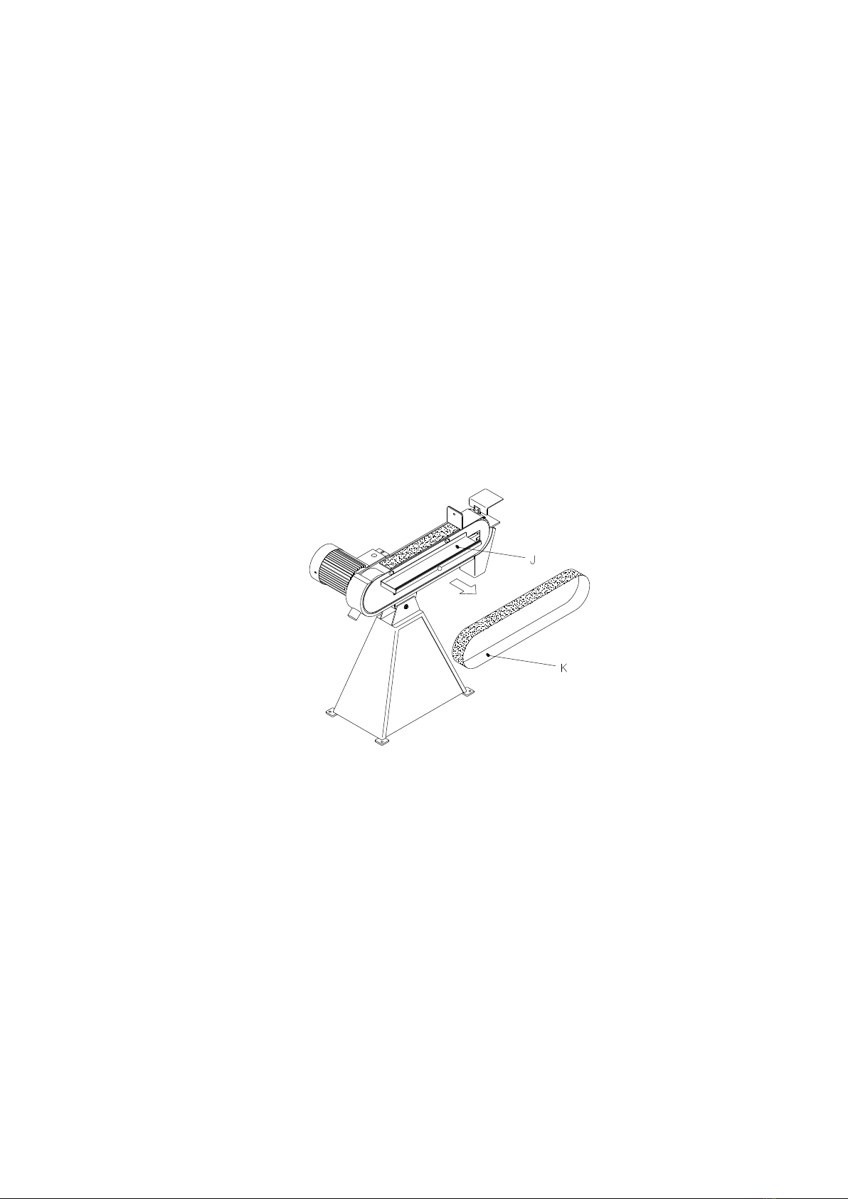
After adjustment and connection, the belt grinding machine is ready for use. The
grinding can take place by the contact wheel (E) or on the surface grinding table by
opening the cover (H). The lifetime of a new belt is prolonged if the grinding starts
with a light pressure.
Please note these safety rules: the machine is designated for use only with non-
spark materials, such as Aluminium-bronze- yellow metal.
Never use steel or any type of metal that when grinded will dispose sparks.
2.2 Security
The existing safety rules must be kept in order to avoid personal or material injury
when working with the belt grinder.
A. User
Do not wear loose clothing, gloves, rings, bracelets, or other jewellery to get caught
in moving parts. Nonslip footwear is recommended. Wear protective hair covering to
contain long hair.
Always wear eye protection and face or dust mask if the operation is dusty. Ordinary
glasses cannot replace eye protection.
Don´t overreach. Keep proper footing and balance at all times.
Never leave tool running unattended. Turn power off. Don´t leave tool until it comes
to a complete stop.
Don´t operate tool while under influence of drugs, alcohol, or any medication.
B. Use of Machine
Use right tool. Don´t force tool or attachment to do a job for which it was not
designed.
Use recommended accessories. Consult the owner´s manual for recommended
accessories. The use of improper accessories may cause hazards.
C. Adjustment
Make all adjustments with the power off. In order to obtain the machine precision and
correct ways of adjustment while assembling, the user should read the detailed
instruction in this manual.
D. Working Environment
Keep work area clean. Cluttered areas and benches invite accidents.
Don´t use in dangerous environment. Don´t use power tools in damp or wet locations
or expose them to rain. Keep work area well-lighted.

7
Keep children and visitors away. All children and visitors should be kept a safe
distance from work area.
E. Maintenance
Disconnect machine from power source when making repairs.
Check damaged parts. To read every details of trouble shooting, repair it very crefully
and make sure the operator won´t get injurt and damage the machine.
2.3 Maintenance
Empty the spark box with regular intervals and control if the suction canals need a
cleaning. Empty or change the dust bag as required. The contact wheel should be
replaced when the edges have been worn round or the tyre has been damaged. The
graphite pad on the surface grinding table is changed as required.
Fig.: 2.1
When changing the belt it is released by turning the handle (I) in anti-clock-wise
direction (see fig.: 2.1), the cover (J) is opened and the worn-down belt (K) is removed
by driving the belt against the direction of rotation, and the belt is removed from the
machine by the drive wheel. The new belt is fitted. It must be checked that the
direction of the arrows on the back side of the belt correpsond to the direction of
rotation. The handle (I) is turned clockwise until grinding belt is tightened. Check for
alignment by turning the grinding belt by hand and adjust with handle (D)

8
Fig.: 2.2
To change the contact wheel remove the grinding belt, tool rest and spark arrester.
Use a 6 mm mandel to hammer out the pin (L). Now the contact wheel with axle and
bearings can be taken out. One of the lock rings (M) and the axle (N) can be taken out.
The new contact wheel (O) is fitted in in reverse order.

9
3.0 Spare Parts List
3.3 Drawing for Belt Grinding Machine with Exhaust System

10
3.4 Spare parts List for Belt Grinding
Machine with Exhaust System
When ordering spare parts please state
machine type and serial number together with item number and description of the
part according to this list.
Item No.
Description
1
Belt release handle
0102267
2
Belt guard
1055603
4
Spark arrester/tool rest
1055618
5
Eye shield
0233605
6
Split pin ø6x50 mm
0233050
7
Tool rest
1055610
8
Handle for tool rest
0233808
9
Screw M10x25
0300134
10
Support for tool rest
0104373
11
Suction hose ø63
7891011
13
Fan cover for exhaust
motor
2075180
14
Dust bag
0811793
15
Handle M6x25
0233025
16
Lock nut M12
0231345
17
Cable
0963084
18
Fan cover for motor
2031017
19
DISA switch
0188826
20
Screw M8x12
0300144
21
Graphite pad
0233221
22
Spring 5,5x43x125x11 mm
0102265
23
Cradle for contact wheel
0110223
25
Star handle Ø32 M6x16
0233806
26
Screw M8x20
0233020
27
Screw M12x100
4567832
29
Drive wheel
7520028
33
Hose strap 58-75 mm
0233058
35
Side plate
1055619
36
Grinding belt
-
37
Screw M6x45 CH
0950614
38
Dust extractor
0233853
39
Fan wheel for motor
2031016
41
Fan wheel for exhaust
motor
2031015
42
Contact wheel with ball
bearings
1535005
44
Ball handle M6xØ25
0331662
Fig.: 3.2

11
47
Lock nut M8
0231347
49
Contact for DISA switch
0110049
50
Sheet metal screw
2.9x6.5
0110050
51
Screw CH M5x10
0120628
52
Blind stopper Ø20
0105153
53
Box for DISA switch
0105152
54
Cable disc PG 11
0105154
55
Split pin Ø4x50 mm
3454351
56
Disc 10x45x4
0860327
57
Disc 10mm
0101491
58
Disc 10mm
2323212
59
Disc 8 mm
5437850
60
Screw M4x8
0100425
61
Lock nut M6
0951406
62
Hinge mounting for eye
shields
0921475
64
Disc 8mm
6540981
66
Lock ring Ø20
0311262
67
Axle
0233251
68
Lock ring Ø7
0915720
69
Rubber list
0110069
70
Screw M6x12
0930612
71
Wave spring 14x0.3x21
0102268
72
Eccentric for 8 mm motor
sheet
0752262
73
Disc 8mm
6540985
77
Parallel key 36x6x6
0110077
78
Screw M4x5
0737620
79
Motor
2030041
80
Parallel key
-
81
Screw M4x12
0737610
82
Cover for terminal box
0110082
83
Exhaust motor 0.5HP
2030039
84
Fan wheel large 250 mm
0995704
85
Disc 5mm
0233030
86
Screw M5x30
0331786
88
Disc 6mm
0737631
89
Screw M6x10
0110089
92
Disc 8mm
5437850
93
Suction box for exhaust
system
2578909
94
Suction hose ø102 mm
6721303
95
Hose strap 90-110 mm
0233110
96
Spark box with exhaust
system
1055600
97
Star M6
0233807
98
Plant to level
1055679

12
3.3 Cylon with stand.
3.4 Spare Parts List for Cylon with stand.
When ordering spare parts please state machine type and serial number together
with item number and description of the part according to this list.
Pos. Nr.
Benævnelse
75X-2000
1
Cylon w/ Exhaust System
700681300
2
Stand to cyklon
1055595

13
Technical Data
4.1 Technical Specifications
Model
75X
Grinding belt
75x2000
Motor 3x380-440 V 50 Hz
4,1 HK
Class
IEC 34-1
IP Class
54
r/min.
2800
Amp
10.6/6.1
Cos
0,91
Belt speed
30 m/s
Contact wheel
Ø200x75
Fan motor
0,5 HK
Weight
111 kg
The noise level for Silverstar belt grinding machine has been measured to 85 dB(A) according to the
measuring instruction in the note 561 from the Work Inspection Department on device of technical aids.
4.2 Dimensions
Fig.: 4.2
Model
A
B
C
D
E
F
G
H
I
J
K
75
995
540
945
830-970
605
635
365
395
413
306
107

14
4.3 Wiring diagram
Belt grinding machines can be connected to 3 x 400/440 V, 50/60 cycles and to
Below please find a wiring diagram informing how to connect the machine to the
wiring supply.
3x400/440 Volt, 50/60 cycles
with exhaust system

15
5.0 Warranty
5.1 Guarantee
If within 2 year of purchase this machine supplied by KEF A/S becomes defective due
to faulty materials or workmanship we guarantee to repair or replace the machine or
defective part or parts free of charge provided that:
1. The product is returned complete to one of our Service Branches or Official
Service Agents.
2. The product has not been misused or carelessly handled and in particular has not
been used in a manner contrary to the operating instructions.
3. Repairs have not been made or attempted by other than our own Service Staff or
the staff of our Official Service Agents.
4. Documentary proof of purchase date is produced when the goods are handed in or
sent for repair.
5. Wear parts are not covered by the warranty
KEF A/S offers you five years guarantee on the electrical motor if the motor
becomes defective or even burns-out within the first 5 years from date of invoice
Table of contents
Other KEF Grinder manuals
Popular Grinder manuals by other brands

Makita
Makita 9564PC instruction manual

Nitto
Nitto MYTON MAGW-40 instruction manual

Westfalia
Westfalia WS920 Original instructions

EINHELL
EINHELL LE-WS 230/3 operating instructions

Matrix
Matrix AG 2200-230 Translation of the original instructions

Parkside
Parkside PGS 500 A1 Translation of the original instructions